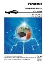
background image

Installation Manual

Pure IP-PBX

Thank you for purchasing a Panasonic Pure IP-PBX.
Please read this manual carefully before using this product and save this manual for future use.

KX-NCP500/KX-NCP1000: PBMPR Software File Version 5.0000 or later

Model No.        

KX-NCP500

KX-NCP1000

SD Logo is

a trademark of

SD-3C, LLC.

Summary of Contents for KX-NCP1000

Page 1: ...ing a Panasonic Pure IP PBX Please read this manual carefully before using this product and save this manual for future use KX NCP500 KX NCP1000 PBMPR Software File Version 5 0000 or later Model No KX NCP500 KX NCP1000 SD Logo is a trademark of SD 3C LLC ...

Page 2: ...l IP Softphone IP Proprietary Telephone Activation Key 8 IP Softphone IP PT KX NCS3216 16 Channel IP Softphone IP Proprietary Telephone Activation Key 16 IP Softphone IP PT KX NCS3501 1 Channel IP Proprietary Telephone Activation Key 1 IP PT KX NCS3504 4 Channel IP Proprietary Telephone Activation Key 4 IP PT KX NCS3508 8 Channel IP Proprietary Telephone Activation Key 8 IP PT KX NCS3516 16 Channe...

Page 3: ...IPEXT32 Virtual 4 IP Cell Station Interface Card V IPCS4 Small Free Slot Physical Trunk Cards KX NCP1180 4 Port Analogue Trunk Card LCOT4 KX NCP1280 2 Port BRI Card BRI2 KX NCP1290CE PRI Card PRI30 KX NCP1290CJ PRI Card PRI30 KX NCP1290CN PRI Card PRI30 KX NCP1290 PRI Card PRI23 Physical Extension Card KX NCP1170 4 Port Digital Hybrid Extension Card DHLC4 Regular Free Slot Physical Trunk Cards KX ...

Page 4: ...ion KX TDA0155LA 2 Channel Cell Station Unit Using a DHLC DLC Card PT interface CS for DECT Portable Station KX TDA0158CE 8 Channel High density Cell Station Unit Using a DHLC DLC Card PT interface CS for DECT Portable Station KX NCP0158CE 8 Channel IP Cell Station Unit Using a V IPCS4 Card for DECT Portable Station DECT 6 0 KX TDA0155 DECT 6 0 2 Channel Cell Station Unit Using a DHLC DLC Card PT ...

Page 5: ...ports SIP Extensions However some PBX features may not be available for SIP Extensions depending on your telephone type Under power failure conditions the connected telephones may not operate Please ensure that a separate telephone not dependent on local power is available for emergency use Prior to connection of this product please verify that the intended operating environment is supported Satis...

Page 6: ...e and prevent damage to property The notices are classified as follows according to the severity of injury or damage WARNING This notice means that misuse could result in death or serious injury CAUTION This notice means that misuse could result in injury or damage to property 6 Installation Manual Safety Notices ...

Page 7: ... strips extension cords etc are used in a manner that exceeds their rated capacity they emit large amounts of heat which could cause a fire Unplug the product from the wall outlet and have it serviced by qualified service personnel in the following cases a When the power supply cord or plug is damaged or frayed b If liquid has been spilled into the product c If the product has been exposed to rain...

Page 8: ... The power supply cord is used as the main disconnect device Ensure that the AC outlet is located near the equipment and is easily accessible The SD Memory Card poses a choking hazard Keep the SD Memory Card out of reach of children Slots and openings in the front back and bottom of the cabinet are provided for ventilation to protect it from overheating these openings must not be blocked or covere...

Page 9: ...e disposal 7 When user information is sent from the PBX to a PC or other external device the confidentiality of that information becomes the responsibility of the customer Before disposing of the PC or other external device ensure that data cannot be retrieved from it by formatting the hard disk and or rendering it physically unusable Notice SAFETY REQUIREMENTS For All Telephone Equipment Read and...

Page 10: ...structions The following or similar rack mount instructions are included with the installation instructions a Elevated Operating Ambient If installed in a closed or multi unit rack assembly the operating ambient temperature of the rack environment may be greater than room ambient Therefore consideration should be given to installing the equipment in an environment compatible with the maximum ambie...

Page 11: ...n below If in any doubt please consult a qualified electrician WARNING This appliance must be earthed IMPORTANT The wires in the mains lead are coloured as follows Green and yellow Earth Blue Neutral Brown Live As the colours of the wires in the mains lead of this apparatus may not correspond with the coloured markings identifying the terminals in your plug proceed as follows The wire that is colo...

Page 12: ...lectrical and electronic equipment please contact your dealer or supplier for further information Information on Disposal in other Countries outside the European Union These symbols are only valid in the European Union If you wish to discard these items please contact your local authorities or dealer and ask for the correct method of disposal Note for the battery symbol bottom two symbol examples ...

Page 13: ...C ACCESS TO OTHER CARRIERS FOR TOLL CALLS When calling back a number from the Caller ID list all numbers prefixed with 0 AREA CODE will be automatically forwarded to your toll carrier This includes numbers in your local calling area The zero area code should either be removed when calling back local numbers or check with your toll carrier that a charge will not be levied All persons using this dev...

Page 14: ... with this Installation Manual the following manuals are available Feature Guide Describes all basic optional and programmable features of the PBX PC Programming Manual Provides step by step instructions for performing system programming using a PC PT Programming Manual Provides step by step instructions for performing system programming using a PT User Manual Provides operating instructions for e...

Page 15: ...taching a Ferrite Core 53 3 2 7 19 inch Rack Mounting 54 3 2 8 Floor Standing 55 3 2 9 Surge Protector Installation 56 3 3 Information about the Main Processing Card 59 3 3 1 IPCMPR Card 59 3 3 2 DSP4 Card KX NCP1104 DSP16 Card KX TDE0110 and DSP64 Card KX TDE0111 62 3 3 3 RMT Card KX TDA0196 64 3 4 Information about the Virtual Cards 65 3 4 1 Virtual Cards 65 3 5 Information about the Physical Tr...

Page 16: ...eripherals 117 3 10 1 Connection of Peripherals 117 3 11 LAN Connection 121 3 11 1 LAN Connection 121 3 12 Power Failure Connections 122 3 12 1 Power Failure Connections 122 3 13 Starting the PBX 124 3 13 1 Starting the PBX 124 4 Guide for the Maintenance Console 127 4 1 Overview 128 4 1 1 Overview 128 4 2 PC Connection 129 4 2 1 PC Connection 129 4 3 Installation of the Maintenance Console 131 4 ...

Page 17: ...Section 1 System Outline This section provides general information on the PBX including the system capacity and specifications Installation Manual 17 ...

Page 18: ...in Unit The main unit contains a power supply unit PSU and an IPCMPR card for starting and controlling the PBX KX NCP500 KX NCP1000 Construction of the Main Unit A IPCMPR Card A A KX NCP500 KX NCP1000 18 Installation Manual 1 1 1 Main Unit ...

Page 19: ...one Fax Machine PC USB APT DPT ISDN Telephone Amplifier SLT DSS Console DSS Console External Sensor External Relay Device IP PT IP Softphone CA 3 Client PC PC PC CTI Server SIP Extension Private IP Network ITSP 1 Network DCE 2 e g ADSL Modem WAN KX DT346 KX DT343 PC USB KX DT300 KX DT300 IP CS PS 1 ITSP Internet Telephony Service Provider 2 DCE Data Circuit Terminating Equipment 3 CA Communication...

Page 20: ...ternal Sensor External Relay Device Virtual Trunk Slot Virtual Extension Slot Telephone Company Analogue Trunk ISDN BRI Line Digital Trunk ISDN PRI Line Digital Trunk E1 KX NCP1188 T1 KX NCP1187 T1 Line Digital Trunk E1 Line Digital Trunk Station Message Detail Recording SMDR PC Router Radio Amplifier Pager Speaker PC IP Softphone CA Client PC LAN CTI Server IP PT SIP Extension IP CS Private IP Ne...

Page 21: ... SLC16 16 Port Single Line Telephone Extension Card SLC16 KX NCP1180 4 Port Analogue Trunk Card LCOT4 4 port analogue trunk card with 1 power failure transfer PFT port KX NCP1187 T 1 Trunk Card T1 1 port T1 trunk card EIA TIA standard compliant KX NCP1188 E 1 Trunk Card E1 1 port E1 trunk card ITU T standard compliant KX NCP1190 Optional 3 Slot Base Card OPB3 Optional 3 slot base card for mounting...

Page 22: ...mplified voice message card for Built in Simplified Voice Message feature Also supports MSG card features To be mounted on the OPB3 card KX TDA0196 Remote Card RMT Analogue modem card for remote communication with the PBX ITU T V 90 support To be mounted on the IPCMPR card KX TDE0110 16 Channel VoIP DSP Card DSP16 16 channel digital signal processor card with a 4 Channel IP Trunk activation key an...

Page 23: ...ion 7 years Dialling Trunk Dial Pulse DP 10 pps 20 pps Tone DTMF Dialling Extension Dial Pulse DP 10 pps 20 pps Tone DTMF Dialling Mode Conversion DP DTMF DTMF DP Ring Frequency 20 Hz 25 Hz selectable Trunk Loop Limit 1600 W maximum Operating Environment Temperature 0 C to 40 C Humidity 10 to 90 non condensing Conference Call Trunk From 10 3 party conference call to 4 8 party conference call Music...

Page 24: ...rface CS 8 channel 4 pair wire D1 D2 DSS Console and Add on Key Module 1 pair wire D1 D2 Dimension KX NCP500 430 mm W 88 mm H 340 mm D KX NCP1000 430 mm W 130 mm H 340 mm D Weight when fully mounted KX NCP500 Under 7 kg KX NCP1000 Under 8 kg 1 If tolerance may be exceeded an Uninterruptible Power Supply UPS is recommended 24 Installation Manual 1 3 1 General Description ...

Page 25: ...imum Hookswitch Flash Recall Timing Range 24 ms to 2032 ms BRI Cards Internal ISDN Mode Supply Voltage 40 V Power Supply BRI2 4 5 W per 1 line 9 W per 2 lines Power Supply Method Phantom Power Supply Door Opener Current Limit 24 V DC 30 V AC 1 A maximum External Relay Current Limit 24 V DC 30 V AC 1 A maximum External Sensor Current Limit Power to the external sensor is provided from the EIO4 card...

Page 26: ...mum Number KX NCP500 KX NCP1000 IPCMPR Card Slot 1 1 Regular Free Slot 2 3 Small Free Slot 3 4 Virtual Slot Virtual Trunk Slot 4 4 Virtual Extension Slot 4 4 IPCMPR Card Slot and Free Slots KX NCP500 KX NCP1000 A B C B C A A Small Free Slots B Regular Free Slots C IPCMPR Card Slot 26 Installation Manual 1 3 3 System Capacity ...

Page 27: ...Virtual Slots of the IPCMPR Card Example Virtual Slots of the KX NCP1000 IPCMPR Card Virtual Slots Virtual Trunk Slots Virtual Extension Slots Installation Manual 27 1 3 3 System Capacity ...

Page 28: ...4 7 4 V IPGW16 4 4 V SIPGW16 LCOT4 BRI2 T1 E1 PRI23 PRI30 V IPEXT32 V SIPEXT32 V IPCS4 IPCMPR Trunk Card Card Type Maximum Number Virtual Trunk Card Total 5 Physical Trunk Card Total 5 Virtual Extension Card Extension Card 2 2 One T1 E1 PRI30 or PRI23 card counts as 2 cards 1 When installing T1 E1 PRI30 PRI23 cards make sure that the number of these cards 2 the number of the other cards does not e...

Page 29: ...e mounted on each OPB3 card Maximum Trunks and Extensions The PBX supports the following number of trunks and extensions Type Maximum Number Total Number of Trunks 128 Trunk Physical Trunk Card 64 Trunk Virtual Trunk Card 64 H 323 Trunks 32 SIP Trunks 64 Total Number of Extensions 172 Extension Physical Extension Card 44 Extension Virtual Extension Card 128 IP PT and IP Softphone 128 SIP Extension...

Page 30: ...2 8 32 1 For example when a virtual extension uses G 711 and a virtual trunk uses G 729A for the same call For Calls between Virtual Trunks and Physical Card Extensions e g DPTs etc Codec Used Maximum Number of Simultaneous Calls DSP4 Card DSP16 Card DSP64 Card G 711 5 32 64 G 729A 2 12 50 For Calls between Virtual Extensions and Physical Card Extensions Trunks e g PRI etc Codec Used Maximum Numbe...

Page 31: ...nnel 16 PS 64 Voice Processing System VPS 2 Doorphone 16 4 Door Opener 16 External Sensor 16 External Relay 16 1 KX NT400 KX NT300 series and KX NT265 software version 2 00 or later only 2 For the KX NT400 the maximum number of extensions that can be connected to the PBX is 64 3 One 8 channel PT interface CS or IP CS counts as 2 CSs up to a maximum of 32 CSs Therefore the maximum number of CSs is ...

Page 32: ...umber of connected DPTs the maximum number of DPTs the PBX can support The table below shows examples of how many Digital XDP ports can be assigned with different configurations For details about the Digital XDP connection refer to 3 8 3 Digital EXtra Device Port Digital XDP Connection Config 1 Config 2 Config 3 Config 4 Config 5 Small Free Slot DHLC4 DHLC4 Regular Free Slot DLC16 DLC16 DLC8 DLC16...

Page 33: ...C8 8 SLC16 16 PT interface CS 2 channel 1 unit 4 PT interface CS 8 channel 1 unit 8 IP CS 8 channel 1 unit 0 ISDN Extension 2 VPS 1 port 1 1 Only the extension cards that can support SLTs count for the load figures Notice If the total load figure exceeds the maximum load figure of the PBX by 3 the corresponding extension card cannot be supported by the PBX Calculation Example Lines and Equipment L...

Page 34: ...T 16 units 16 SLC16 KX NT300 series IP PT 40 units 0 V IPEXT32 2 SIP Extension 0 0 VPS 0 0 CS 0 0 1 At least 4 of the 20 DPT ports of DHLC4 and DLC16 cards must be assigned as Digital XDP ports The total load figure in the example is 44 and is calculated as follows 24 units 1 1 DHLC4 card 4 1 SLC16 card 16 44 34 Installation Manual 1 3 3 System Capacity ...

Page 35: ...Section 2 Activation Key Installation This section describes information on activation keys including how to obtain an activation key and install it in the SD Memory Card Installation Manual 35 ...

Page 36: ... IP PT 2 Allows the use of 4 IP PTs IP softphones 32 8 IP Softphone IP PT 2 Allows the use of 8 IP PTs IP softphones 16 16 IP Softphone IP PT 2 Allows the use of 16 IP PTs IP softphones 8 1 IP PT Allows the use of 1 IP PT 128 128 IP PTs 4 IP PT Allows the use of 4 IP PTs 32 8 IP PT Allows the use of 8 IP PTs 16 16 IP PT Allows the use of 16 IP PTs 8 1 SIP Extension Allows the use of 1 SIP Extensio...

Page 37: ...Activation Key Supported IP Trunks IP PTs DSP4 4 Channel IP Trunk 1 4 IP trunks H 323 SIP 8 Channel IP Proprietary Telephone 1 8 IP PTs DSP16 4 Channel IP Trunk 1 4 IP trunks H 323 SIP 8 Channel IP Proprietary Telephone 1 8 IP PTs DSP64 4 Channel IP Trunk 4 16 IP trunks H 323 SIP 8 Channel IP Proprietary Telephone 4 32 IP PTs Depending on the number of IP trunks and IP PTs to be used you need to s...

Page 38: ...es KX NCS3216 16 IP Softphone IP PT 7 112 IP PTs IP softphones 6 96 IP PTs IP softphones KX NCS3501 1 IP PT 120 120 IP PTs 96 96 IP PTs KX NCS3504 4 IP PT 30 120 IP PTs 24 96 IP PTs KX NCS3508 8 IP PT 15 120 IP PTs 12 96 IP PTs KX NCS3516 16 IP PT 7 112 IP PTs 6 96 IP PTs KX NCS3701 1 SIP Extension 128 128 SIP Extensions 128 128 SIP Extensions KX NCS3704 4 SIP Extension 32 32 KX NCS3708 8 SIP Exte...

Page 39: ...xample of when using 16 H 323 trunks 16 SIP trunks 32 IP PTs 16 IP softphones and 16 SIP Extensions on a private IP network using the IPCMPR card Example KX NCP1000 IPCMPR Card Virtual Slots Virtual Trunk Slots 8 Channel IP Proprietary Telephone 8 Channel IP Softphone IP Proprietary Telephone SD Memory Card DSP64 Card 32 IP PTs 16 IP softphones 16 Channel SIP Extension 16 SIP Extensions 4 Channel ...

Page 40: ...an only download the activation key file once using the activation key number and registration ID provided on the activation key code Up to 8 activation keys can be downloaded as one activation key file Up to 100 activation key files can be installed in the SD Memory Card It is possible to send the activation key file to a specified e mail address at the same time as downloading it to a PC Make su...

Page 41: ...ransferring files to the SD memory card the PBX automatically renames them according to the header information A message will be displayed when the transfer is complete 4 Click OK 5 Under Configuration click Slot 6 Click Activation Key 7 For IP trunk activation key file s click Execute A confirmation message will be displayed Click Yes Notice The activation key file can only be installed in the PB...

Page 42: ...42 Installation Manual 2 1 3 Activation Key File ...

Page 43: ...install the PBX Detailed instructions for planning the installation site installing the main unit and optional service cards and cabling of peripheral equipment are provided Further information on peripheral equipment installation is included Installation Manual 43 ...

Page 44: ...m in the following locations Areas where shocks or vibrations are frequent or strong Such activity may lead to the product falling over and causing injury or may impair the product s performance Areas with high amounts of dust High amounts of dust can lead to fire or electric shock and impair the performance of the product CAUTION Do not install the system in the following locations In direct sunl...

Page 45: ...s data terminals answering machines computers Voice Processing Systems etc Mis wiring may cause the PBX to operate improperly Refer to Section 3 Section 3 Installation when wiring the system If an extension does not operate properly disconnect the telephone from the extension line and connect it again or turn off the PBX using the power switch then turn it on again Use twisted pair cable for trunk...

Page 46: ... NCP1000 Main Unit 1 1 Ferrite Core for the IPCMPR card 2 2 AC Cord 1 1 1 1 19 inch Rack Attachment Bracket 2 2 SD Memory Card 1 1 Screw 6 6 1 KX NCP500BX KX NCP1000BX is supplied with 2 types of AC cord Please use whichever is appropriate for the country area 46 Installation Manual 3 2 1 Unpacking ...

Page 47: ...ront Back L J K H I A Small Free Slots B RUN Indicator C Regular Free Slots D ALARM Indicator E IPCMPR Card Slot F MNT Port G LAN Port H Hook Clip I Power Switch J AC Inlet K Earth Terminal L RS 232C Port Note A Power Supply Unit PSU is pre installed Installation Manual 47 3 2 2 Names and Locations ...

Page 48: ...noise in the case of a lightning strike The earthing wire of the AC cable has an effect against external noise and lightning strikes but it may not be enough to protect the PBX A permanent connection between earth and the earth terminal of the PBX must be made CAUTION For earthing wire green and yellow insulation is required and the cross sectional area of the conductor must be more than 0 75 mm2 ...

Page 49: ...the label is attached to an optional service card for small free slots be sure to turn the power switch off before installing or removing the card When installing or removing the IPCMPR card the DC power supply must be turned off Installing Removing Optional Service Cards 1 Turn the 2 screws anticlockwise to remove the appropriate slot panel Screws 2 Insert the card along the guide rails Guide Rai...

Page 50: ...ise to fix the card in place Screws 4 To remove the card reverse the procedure above Note Make sure the screws are tightened to earth the card securely 50 Installation Manual 3 2 4 Installing Removing the Optional Service Cards ...

Page 51: ...P1173 SLC16 KX NCP1174 LCOT4 KX NCP1180 T1 KX NCP1187 E1 KX NCP1188 BRI2 KX NCP1280 PRI30 KX NCP1290CE KX NCP1290CJ KX NCP1290CN PRI23 KX NCP1290 BNC 1 2 E1 KX NCP1188 10 pin Terminal Block 8 pin Terminal Block 8 1 10 1 DPH4 KX TDA0161 DPH2 KX TDA0162 EIO4 KX TDA0164 RS 232C 9 5 6 1 Main Unit Shielded cable Installation Manual 51 3 2 5 Types of Connectors ...

Page 52: ...Connector Type Pin Number Used for Mini Plug 2 4 IPCMPR 52 Installation Manual 3 2 5 Types of Connectors ...

Page 53: ...e is included with the PBX 3 cm For the E1 PRI30 Cards Wrap the cable once around the ferrite core then close the case of the ferrite core Attach the ferrite core 5 cm away from the connector The ferrite core is included with the card 5 cm For the BRI2 Card Wrap the cable s once around the ferrite core then close the case of the ferrite core Attach the ferrite core as close to the card s connector...

Page 54: ...e the temperature of the rack to exceed its limit If the PBX is not installed properly using the securing correct methods the PBX may fall causing serious damage When this product is no longer in use make sure to detach it from the rack 1 Fix the attachment brackets to the left and right sides of the PBX with 3 screws 1 2 Place the PBX in the 19 inch rack and fix both attachment brackets to the ra...

Page 55: ...aced as indicated in the diagram below Do not place it on its side or upside down Do not block the openings of the PBX Allow space of at least 20 cm above and 10 cm at the sides of the PBX Make sure that the surface behind the PBX is flat and free of obstacles so that the openings on the back of the PBX will not be blocked Make sure that the surface behind the PBX is not made of wood Floor Install...

Page 56: ... protect the system from electrical surges we strongly recommend connecting the system to a surge protector that meets the following specifications Surge arrestor type 3 electrode arrestor DC spark over voltage 230 V Maximum peak current at least 10 kA Additionally proper earthing is very important for the protection of the system refer to 3 2 3 Frame Earth Connection Many countries areas have reg...

Page 57: ...ce CS If you install an extension outside of the building the following precautions are recommended a Install the extension wire underground b Use a conduit to protect the wire Note The surge protector for an extension and CS is different from that for trunks Installation of an Earth Rod Trunk PBX Earth Rod Underground Surge Protector Earthing Wire Installation Manual 57 3 2 9 Surge Protector Inst...

Page 58: ...wire should be as short as possible 3 The earthing wire should run straight to the earth rod Do not run the wire around other objects 4 Bury the earth rod at least 50 cm underground Note The above figures are recommendations only The length of earth rod and the required depth depend on the composition of the soil 58 Installation Manual 3 2 9 Surge Protector Installation ...

Page 59: ...SP16 Card KX TDE0110 and DSP64 Card KX TDE0111 RMT card refer to 3 3 3 RMT Card KX TDA0196 2 4 1 5 3 SD Memory Card LEDs SD Memory Card Slot Cover Reset Button LAN Port MNT Port BGM MOH Pager MPR ID Number MNT Port LAN Port To LAN To PC LEDs System Initialise Switch Note Make sure to use the MNT port for PC connection and the LAN port for LAN connection The maximum length of the cable to be connec...

Page 60: ... be easily removed and taken away from the PBX by a third party Therefore do not allow unauthorised access to prevent data leakage Do not remove the SD Memory Card while power is supplied to the PBX Doing so may cause the PBX to fail to start when you try to restart the system To prevent data leakage render the SD Memory Card physically unusable before disposal Notice Use only the SD Memory Card i...

Page 61: ... normally Flashing In communication 100 Yellow Data transmission speed indication OFF 10 Mbps ON 100 Mbps LAN 1 LINK Green Link status indication OFF Off line ON Linked normally Flashing In communication 100 Yellow Data transmission speed indication OFF 10 Mbps ON 100 Mbps Installation Manual 61 3 3 1 IPCMPR Card ...

Page 62: ...Trunk activation keys and four 8 Channel IP Proprietary Telephone activation keys preinstalled Compliant with ITU T G 729A and G 711 codec methods To be mounted on the IPCMPR card DSP4 Card DSP16 Card DSP64 Card Screws inside Accessories and User supplied Items Accessories included Screws 3 User supplied not included none Note Depending on the number and the type of IP trunks and IP telephones you...

Page 63: ... When installing the DSP card hold down the shaded areas of the card to connect it firmly Installation Manual 63 3 3 2 DSP4 Card KX NCP1104 DSP16 Card KX TDE0110 and DSP64 Card KX TDE0111 ...

Page 64: ...ote communication with the PBX ITU T V 90 support To be mounted on the IPCMPR card RMT Card IPCMPR Card Screws inside Accessories and User supplied Items Accessories included Screws 2 User supplied not included none 64 Installation Manual 3 3 3 RMT Card KX TDA0196 ...

Page 65: ...PGW16 Virtual Card for 16 channel SIP trunk Compliant with RFC 3261 3262 3264 3311 3581 3960 and 4028 protocols and ITU T G 729A and G 711 codec methods Also supports T 38 protocol Virtual 32 Channel VoIP Extension Card V IPEXT32 Virtual Card for 32 VoIP extensions Compliant with Panasonic proprietary protocol and ITU T G 729A G 711 and G 722 codec methods Virtual 32 Channel SIP Extension Card V S...

Page 66: ...d Items Accessories included none User supplied not included RJ45 connector Note For details about power failure transfer refer to 3 12 1 Power Failure Connections To confirm the trunk connection refer to Confirming the Trunk Connection in 3 13 1 Starting the PBX Pin Assignments RJ45 Connector No Signal Name Function 1 8 R T 1 3 Reserved 4 R Ring 5 T Tip 6 8 Reserved 66 Installation Manual 3 5 1 L...

Page 67: ...n Red Card status indication OFF Power Off Green ON Normal all ports are idle Green Flashing 60 times per minute Normal a port is in use Red ON Fault includes reset Red Flashing 60 times per minute Out of Service Installation Manual 67 3 5 1 LCOT4 Card KX NCP1180 ...

Page 68: ... the trunk directly T1 ports are SELV ports and should only be connected to SELV services Note This optional service card can be used for either trunk or extension connection by setting the A B switch or using the connector with appropriate pin assignments To confirm the trunk connection refer to Confirming the Trunk Connection in 3 13 1 Starting the PBX Switch Settings Switch Type Usage and Statu...

Page 69: ... Indication Colour Description CARD STATUS Green Red Card status indication OFF Power Off Green ON Normal all ports are idle Green Flashing 60 times per minute Normal a port is in use Red ON Fault includes reset Red Flashing 60 times per minute Out of Service SYNC ERR Red Non synchronisation status indication OFF Normal ON Out of synchronisation RAI Red RAI signal status indication OFF Normal ON A...

Page 70: ...sed ON Synchronised Flashing 60 times per minute Synchronised Clock Master Maximum Cabling Distance of Extension Connection The maximum length of the extension cable that connects the T1 cards is shown below Diameter Maximum Distance 0 5 mm 200 m 70 Installation Manual 3 5 2 T1 Card KX NCP1187 ...

Page 71: ...t to the trunk directly E1 ports are SELV ports and should only be connected to SELV services Notice When connecting the RJ45 connector attach the included ferrite core Refer to 3 2 6 Attaching a Ferrite Core Note In some countries areas this optional service card must not be connected to the Public Switched Telephone Network Use only 1 type of connector RJ45 or BNC for connection RJ45 and BNC can...

Page 72: ...X outer conductor Connection of 1 and 2 Open default Connection of 2 and 3 Short Pin Assignments RJ45 Connector for Trunk Use No Signal Name Level V Function 8 1 1 RX Receive data 2 RX Receive data 3 Reserved 4 TX Transmit data 5 TX Transmit data 6 8 Reserved RJ45 Connector for Extension use No Signal Name Level V Function 8 1 1 TX Transmit data 2 TX Transmit data 3 Reserved 4 RX Receive data 5 RX...

Page 73: ...nchronisation status indication OFF Normal ON Out of synchronisation RAI Red RAI signal status indication OFF Normal ON Alarm Clock Slave Flashing 60 times per minute Alarm Clock Master AIS Red AIS status indication OFF Normal ON Alarm SYNC Green Synchronisation status indication OFF Not synchronised ON Synchronised Flashing 60 times per minute Synchronised Clock Master Maximum Cabling Distance of...

Page 74: ...he terminal When connecting this optional service card to the trunk connect through an NT1 do not connect to the U interface of the trunk directly Notice When connecting the RJ45 connector attach the included ferrite core Refer to 3 2 6 Attaching a Ferrite Core Note This optional service card has 100 W of terminal resistance For use in point to multi point connection the card must be placed at the...

Page 75: ...2 6 RX1 Receive data 1 7 8 Reserved LED Indications Indication Colour Description CARD STATUS Green Red Card status indication OFF Power Off Green ON Normal all ports are idle Green Flashing 60 times per minute Normal a port is in use Red ON Fault includes reset Red Flashing 60 times per minute Out of Service LINE 2 LINE 1 Green Line status indication LINE 1 and LINE 2 Refer to LINE LED Pattern be...

Page 76: ...N Master OFF Slave Maximum Cabling Distance of S0 Bus Connection The maximum length of the extension cable that connects the PBX and the ISDN terminal equipment TE is shown below TE CAT 5 Under 1000 m CAT 5 Under 150 m CAT 5 Under 50 m CAT 5 Under 500 m TE 1 TE 1 TE 8 TE 8 Point to Point Point to Multipoint Expansion Point to Multipoint 76 Installation Manual 3 5 4 BRI2 Card KX NCP1280 ...

Page 77: ...rvices Notice When connecting the RJ45 connector attach the included ferrite core Refer to 3 2 6 Attaching a Ferrite Core Note In some countries areas this optional service card must not be connected to the Public Switched Telephone Network This optional service card can be used for either trunk or extension connection by setting the A B switch or using the connector with appropriate pin assignmen...

Page 78: ...our Description CARD STATUS Green Red Card status indication OFF Power Off Green ON Normal all ports are idle Green Flashing 60 times per minute Normal a port is in use Red ON Fault includes reset Red Flashing 60 times per minute Out of Service SYNC ERR Red Non synchronisation status indication OFF Normal ON Out of synchronisation RAI Red RAI signal status indication OFF Normal ON Alarm Clock Slav...

Page 79: ...onised Clock Master D LINK Green Data link status indication OFF Not established ON Established Maximum Cabling Distance of Extension Connection The maximum length of the extension cable that connects the PRI30 cards is shown below Diameter Maximum Distance 0 5 mm 200 m Installation Manual 79 3 5 5 PRI30 Card KX NCP1290CE KX NCP1290CJ KX NCP1290CN ...

Page 80: ...1 do not connect to the U interface of the trunk directly PRI ports are SELV ports and should only be connected to SELV services Note This optional service card can be used for either trunk or extension connection by setting the A B switch or using the connector with appropriate pin assignments To confirm the trunk connection refer to Confirming the Trunk Connection in 3 13 1 Starting the PBX Swit...

Page 81: ...Indication Colour Description CARD STATUS Green Red Card status indication OFF Power Off Green ON Normal all ports are idle Green Flashing 60 times per minute Normal a port is in use Red ON Fault includes reset Red Flashing 60 times per minute Out of Service SYNC ERR Red Non synchronisation status indication OFF Normal ON Out of synchronisation RAI Red RAI signal status indication OFF Normal ON Al...

Page 82: ... minute Synchronised Clock Master D LINK Green Data link status indication OFF Not established ON Established Maximum Cabling Distance of Extension Connection The maximum length of the extension cable that connects the PRI23 cards is shown below Diameter Maximum Distance 0 5 mm 200 m 82 Installation Manual 3 5 6 PRI23 Card KX NCP1290 ...

Page 83: ... PFT port RJ45 LED To extensions Accessories and User supplied Items Accessories included none User supplied not included RJ45 connector Note For details about power failure transfer refer to 3 12 1 Power Failure Connections Pin Assignments RJ45 Connector No Signal Name Function 1 8 D1 T R D2 1 2 Reserved 3 D1 Data port High 4 T Tip 5 R Ring 6 D2 Data port Low 7 8 Reserved Installation Manual 83 3...

Page 84: ...Green ON Normal all ports are idle Green Flashing 60 times per minute Normal a port is in use Orange Flashing Detection of PT interface CS connection when starting up the PT interface CS Red ON Fault includes reset Red Flashing 60 times per minute Out of Service 84 Installation Manual 3 6 1 DHLC4 Card KX NCP1170 ...

Page 85: ...1 2 Reserved 3 D1 Data port High 4 5 Reserved 6 D2 Data port Low 7 8 Reserved LED Indications Indication Colour Description CARD STATUS Green Orange Red Card status indication OFF Power Off Green ON Normal all ports are idle Green Flashing 60 times per minute Normal a port is in use Orange Flashing Detection of PT interface CS connection when starting up the PT interface CS Red ON Fault includes r...

Page 86: ... 1 2 Reserved 3 D1 Data port High 4 5 Reserved 6 D2 Data port Low 7 8 Reserved LED Indications Indication Colour Description CARD STATUS Green Orange Red Card status indication OFF Power Off Green ON Normal all ports are idle Green Flashing 60 times per minute Normal a port is in use Orange Flashing Detection of PT interface CS connection when starting up the PT interface CS Red ON Fault includes ...

Page 87: ...gnments RJ45 Connector No Signal Name Function 1 8 T R 1 3 Reserved 4 T Tip 5 R Ring 6 8 Reserved LED Indications Indication Colour Description CARD STATUS Green Red Card status indication OFF Power Off Green ON Normal all ports are idle Green Flashing 60 times per minute Normal a port is in use Red ON Fault includes reset Red Flashing 60 times per minute Out of Service Installation Manual 87 3 6 ...

Page 88: ...ignments RJ45 Connector No Signal Name Function 1 8 T R 1 3 Reserved 4 T Tip 5 R Ring 6 8 Reserved LED Indications Indication Colour Description CARD STATUS Green Red Card status indication OFF Power Off Green ON Normal all ports are idle Green Flashing 60 times per minute Normal a port is in use Red ON Fault includes reset Red Flashing 60 times per minute Out of Service 88 Installation Manual 3 6...

Page 89: ...ed none WARNING A lithium battery is used in the OPB3 card There is a risk of explosion if the battery is replaced with the incorrect type Dispose of used batteries according to the manufacturer s instructions LED Indications Indication Colour Description CARD STATUS Green Red Card status indication OFF Power Off Green ON Normal all ports are idle Green Flashing 60 times per minute Normal a port i...

Page 90: ...oor openers To doorphones 10 pin 8 pin DPH4 Card Accessories and User supplied Items Accessories included Screws 3 10 pin terminal block 1 8 pin terminal block 1 User supplied not included Copper wire Note For details about connection to doorphones and door openers refer to 3 9 1 Connection of Doorphones Door Openers External Sensors and External Relays 90 Installation Manual 3 7 2 DPH4 Card KX TD...

Page 91: ...2 transmit 6 com2 Doorphone 2 receive 7 DP1 Doorphone 1 transmit 8 com1 Doorphone 1 receive 10 pin Terminal Block No Signal Name Function 10 1 1 2 Reserved 3 OP4b Door opener 4 4 OP4a Door opener 4 com 5 OP3b Door opener 3 6 OP3a Door opener 3 com 7 OP2b Door opener 2 8 OP2a Door opener 2 com 9 OP1b Door opener 1 10 OP1a Door opener 1 com Installation Manual 91 3 7 2 DPH4 Card KX TDA0161 ...

Page 92: ...10 pin 8 pin DPH2 Card To doorphones door openers 1 2 Accessories and User supplied Items Accessories included Screws 3 10 pin terminal block 1 8 pin terminal block 1 User supplied not included Copper wire Note For details about connection to doorphones and door openers refer to 3 9 1 Connection of Doorphones Door Openers External Sensors and External Relays 92 Installation Manual 3 7 3 DPH2 Card ...

Page 93: ... receive 7 Call_1b RT b 1 Doorphone 1 call button 8 Call_1a RT a 1 Doorphone 1 call button com 10 pin Terminal Block No Proprietary Signal Name Standard Signal Name Function 10 1 1 2 Reserved Reserved 3 OP2b TO b 2 Door opener 2 4 OP2a TO a 2 Door opener 2 com 5 OP1b TO b 1 Door opener 1 6 OP1a TO a 1 Door opener 1 com 7 DC2b TS b 2 Doorphone control 2 8 DC2a TS a 2 Doorphone control 2 com 9 DC1b ...

Page 94: ...1a Path_1b DC1b DC1a OP1b OP1a 8 7 6 5 4 3 2 1 L O U B 12V 8V TO 0 V BL Light RT Call Button OP Door Opener Connection Terminal DC Doorphone Current Supply Control Terminal Path Doorphone Call Path Speaker Microphone Shield Call_2b Call_1a Call_2a Call_1b Doorphone 1 Adaptor 220 V BL Door Opener 1 RT L O U B L O U B 12V 8V TO 0 V German type Doorphone 1 94 Installation Manual 3 7 3 DPH2 Card KX TD...

Page 95: ...ernal sensors To external relays 1 2 Accessories and User supplied Items Accessories included Screws 3 10 pin terminal block 1 8 pin terminal block 1 User supplied not included Copper wire Note For details about connection to external sensors and external relays refer to 3 9 1 Connection of Doorphones Door Openers External Sensors and External Relays Installation Manual 95 3 7 4 EIO4 Card KX TDA01...

Page 96: ...com 5 C2b Control 2 6 C2a Control 2 com 7 C1b Control 1 8 C1a Control 1 com 10 pin Terminal Block No Signal Name Function 10 1 1 2 Reserved 3 OP4b Opener 4 4 OP4a Opener 4 com 5 OP3b Opener 3 6 OP3a Opener 3 com 7 OP2b Opener 2 8 OP2a Opener 2 com 9 OP1b Opener 1 10 OP1a Opener 1 com 96 Installation Manual 3 7 4 EIO4 Card KX TDA0164 ...

Page 97: ...pair of sensor and common lines are connected to the EIO4 card for each external sensor The PBX detects input from the sensor when the signal is under 100 W Connection Diagram External Sensor sensor common I O EIO4 OPB3 PBX 5V 5V 10K 33 33 4 7K 4 7K External Relay Current Limit 24 V DC 30 V AC 1 A maximum Installation Manual 97 3 7 4 EIO4 Card KX TDA0164 ...

Page 98: ...upplied Items Accessories included Screws 3 User supplied not included none Note To establish a conference call involving 6 to 8 parties install an ECHO16 card and enable echo cancellation for conferences using the Maintenance Console For details refer to Echo Cancel Conference in 4 18 2 9 System Options of the PC Programming Manual 98 Installation Manual 3 7 5 ECHO16 Card KX TDA0166 ...

Page 99: ... 4 channel message card To be mounted on the OPB3 card OPB3 Card inside MSG4 Card Screws Accessories and User supplied Items Accessories included Screws 3 User supplied not included none Installation Manual 99 3 7 6 MSG4 Card KX TDA0191 ...

Page 100: ... may cause severe damage to the ESVM card Notice When replacing an ESVM card ensure that the status of the OPB3 card is In Service INS and then initialise the ESVM card For details about the initialisation procedure refer to 2 5 5 Tool Simplified Voice Message Delete All Recording in the PC Programming Manual When installing an ESVM card for the first time on an OPB3 card that is already installed...

Page 101: ...500 m ø 0 5 mm 720 m ø 0 6 mm 830 m CAT 5 720 m Cable Maximum Distance ø 0 4 mm 140 m ø 0 5 mm 229 m ø 0 6 mm 360 m CAT 5 229 m Cable Maximum Distance ø 0 4 mm 698 m ø 0 5 mm 1128 m ø 0 6 mm 1798 m CAT 5 1128 m SLT Other PT DPT APT and DSS Console PT interface CS Notice The maximum cabling distance may vary depending on the conditions PT interface CS DPT APT DSS Console SLT DHLC4 Card ü ü ü ü ü SL...

Page 102: ... ü indicates that the extension card supports the terminal 102 Installation Manual 3 8 1 Maximum Cabling Distances of the Extension Wiring Twisted Cable ...

Page 103: ...ith APT For parallel connection eXtra Device Port XDP mode must be disabled for that port through system programming Refer to 1 11 9 Parallelled Telephone and 2 1 1 Extension Port Configuration in the Feature Guide for further information To DHLC4 card 4 conductor wiring cord Connect pins T R D1 and D2 2 conductor wiring cord Connect pins T and R SLT APT Modular T Adaptor Installation Manual 103 3...

Page 104: ...for further information Using a Modular T Adaptor To DHLC4 card SLT DPT Modular T Adaptor 4 conductor wiring cord Connect pins D1 and D2 2 conductor wiring cord Connect pins T and R Using an EXtra Device Port With KX DT300 Series DPT except KX DT321 TO MAIN UNIT PABX TO TEL To DHLC4 card DPT SLT To DHLC4 card To SLT 2 conductor wiring cord Connect pins T and R 4 conductor wiring cord Connect pins ...

Page 105: ...iring cord Connect pins T R D1 and D2 TO MAIN UNIT PABX TO TEL With Other DPT except KX T7560 and KX T7565 To DHLC4 card DPT SLT To DHLC4 card To SLT 2 conductor wiring cord Connect pins T and R 4 conductor wiring cord Connect pins T R D1 and D2 TO TEL TO EMSS or TO MAIN UNIT Installation Manual 105 3 8 2 Parallel Connection of the Extensions ...

Page 106: ...gh system programming parallel connection is not possible Refer to 1 11 9 Parallelled Telephone and 2 1 1 Extension Port Configuration in the Feature Guide for further information With KX DT300 Series DPT Using a Modular T Adaptor Slave DPT Master DPT Cable Maximum Distance ø 0 4 mm 30 m ø 0 5 mm 50 m ø 0 6 mm 60 m CAT 5 50 m Back View of DPTs To DLC8 DLC16 card To DHLC4 card for connection of SLT...

Page 107: ... pins T R D1 and D2 To DLC8 DLC16 card To DHLC4 card for connection of SLT To SLT Slave DPT Master DPT Cable Maximum Distance ø 0 4 mm 30 m ø 0 5 mm 50 m ø 0 6 mm 60 m CAT 5 50 m Back View of DPTs To DLC8 DLC16 card To DHLC4 card for connection of SLT TO MAIN UNIT PABX TO MAIN UNIT PABX TO TEL TO TEL Installation Manual 107 3 8 3 Digital EXtra Device Port Digital XDP Connection ...

Page 108: ... Modular T Adaptor 4 conductor wiring cord Connect pins D1 and D2 2 conductor wiring cord Connect pins T and R Slave DPT Master DPT TO MAIN UNIT PABX TO TEL TO MAIN UNIT PABX Cable Maximum Distance ø 0 4 mm 30 m ø 0 5 mm 50 m ø 0 6 mm 60 m CAT 5 50 m Back View of DPTs To DLC8 DLC16 card To DHLC4 card for connection of SLT 108 Installation Manual 3 8 3 Digital EXtra Device Port Digital XDP Connecti...

Page 109: ... pins T R D1 and D2 Slave DPT Master DPT To SLT TO MAIN UNIT PABX TO TEL TO TEL TO MAIN UNIT PABX Cable Maximum Distance ø 0 4 mm 30 m ø 0 5 mm 50 m ø 0 6 mm 60 m CAT 5 50 m Back View of DPTs To DLC8 DLC16 card To DHLC4 card for connection of SLT To DLC8 DLC16 card To DHLC4 card for connection of SLT Installation Manual 109 3 8 3 Digital EXtra Device Port Digital XDP Connection ...

Page 110: ...conductor wiring cord Connect pins T and R Slave DPT Master DPT TO MAIN UNIT PABX TO DIGITAL TO MAIN UNIT PABX Cable Maximum Distance ø 0 4 mm 30 m ø 0 5 mm 50 m ø 0 6 mm 60 m CAT 5 50 m Back View of DPTs To DLC8 DLC16 card To DHLC4 card for connection of SLT To DLC8 DLC16 card To DHLC4 card for connection of SLT 110 Installation Manual 3 8 3 Digital EXtra Device Port Digital XDP Connection ...

Page 111: ...ord Connect pins T R D1 and D2 Slave DPT Master DPT To SLT TO MAIN UNIT PABX TO TEL TO DIGITAL TO MAIN UNIT PABX Cable Maximum Distance ø 0 4 mm 30 m ø 0 5 mm 50 m ø 0 6 mm 60 m CAT 5 50 m Back View of DPTs To DLC8 DLC16 card To DHLC4 card for connection of SLT To DLC8 DLC16 card To DHLC4 card for connection of SLT Installation Manual 111 3 8 3 Digital EXtra Device Port Digital XDP Connection ...

Page 112: ...conductor wiring cord Connect pins T R D1 and D2 TO DIGITAL TO MAIN UNIT PABX TO TEL Back View of DPTs Cable Maximum Distance ø 0 4 mm 30 m ø 0 5 mm 50 m ø 0 6 mm 60 m CAT 5 50 m To DLC8 DLC16 card To DHLC4 card for connection of SLT To DLC8 DLC16 card To DHLC4 card for connection of SLT 112 Installation Manual 3 8 3 Digital EXtra Device Port Digital XDP Connection ...

Page 113: ... Module must be connected to the DPTs Note The operating system of the PC required for first party call control depends on your CTI application software For details refer to the manual for your CTI application software KX DT343 KX DT346 USB Port USB Cable USB Module To PC KX T7633 KX T7636 USB Cable To PC U L L USB Port USB Module Note The maximum length of the USB cable is 3 m Installation Manual...

Page 114: ...orphones door openers external sensors and external relays are user supplied Maximum Cabling Distance Doorphone Door Opener Cable Maximum Distance ø 0 4 mm 70 m ø 0 5 mm 113 m ø 0 6 mm 180 m CAT 5 113 m External Sensor External Relay Device Installing the Doorphone KX T30865 KX T7765 Note The illustrations shown in the installation procedure are based on the KX T30865 1 Loosen the screw to separat...

Page 115: ... Note Two kinds of screws are included with the doorphone Please choose the appropriate kind for your wall type when a doorphone plate has been fixed to the wall when you wish to install the doorphone directly onto the wall 3 Connect the wires to the screws located in the back cover To 8 pin terminal block 4 Re attach the 2 halves and re insert the screw Installation Manual 115 3 9 1 Connection of...

Page 116: ...r openers external sensors and external relays Refer to 3 7 2 DPH4 Card KX TDA0161 3 7 3 DPH2 Card KX TDA0162 and 3 7 4 EIO4 Card KX TDA0164 for pin assignments Doorphone Door Opener External Sensor External Relay Device 2 Attach the terminal blocks to the connectors of the DPH4 DPH2 EIO4 card on the PBX To doorphones door openers external sensors external relays 116 Installation Manual 3 9 1 Conn...

Page 117: ... mm 10 m ø 0 6 mm 10 m CAT 5 10 m 2 m Back MNT Port RS 232C PC via MNT Port A PC can be connected to the PBX via the MNT port of the IPCMPR card It is used for system programming diagnostics and external system database storage save load functions Pin Assignments No Signal Name Input I Output O Function 8 1 1 TPO O Transmit data 2 TPO O Transmit data 3 TPI I Receive data 4 5 Reserved 6 TPI I Recei...

Page 118: ...inter via RS 232C The PBX is equipped with an RS 232C interface This interface provides communication between the PBX and the user supplied devices such as PC or line printers The RS 232C port is used for system programming SMDR diagnostics and external system database storage save load functions CAUTION To protect the system keep the following in mind 1 Make sure that both connector cases frame g...

Page 119: ...eceive Data RXD input Conveys signals from the printer or the PC Transmit Data TXD output Conveys signals from the unit to the printer or the PC A Mark condition is held unless data or BREAK signals are being transmitted Data Terminal Ready DTR output This signal line is turned ON by the unit to indicate that it is ON LINE Circuit ER DTR ON does not indicate that communication has been established...

Page 120: ... or the PC is ready to receive data from the unit The unit does not attempt to transfer data or receive data when circuit CS CTS is OFF Frame Ground FG Connects to the unit frame and the earth ground conductor of the AC power cord 120 Installation Manual 3 10 1 Connection of Peripherals ...

Page 121: ...able should be a 10BASE T 100BASE TX CAT 5 or higher cable Make sure that all the CAT 5 cables in use are not over 100 m in length Make sure to create a spanning tree for LAN connection in order to prevent loops from occurring in a multi bridged environment Otherwise some packets may circulate for long periods of time and eventually PBX performance system may degrade The CTI server can be used for...

Page 122: ...ailure Connections Analogue trunk card LCOT4 1 PFT port Extension card DHLC4 1 PFT port To 1 analogue trunk card connect only 1 extension card Note By programming the PBX a trunk conversation established during power failure can be maintained even when the power returns and the connection is switched back to the normal configuration from the Power Failure Connection However if no special programmi...

Page 123: ...No Signal Name Function 1 8 R T 1 3 Reserved 4 R Ring 5 T Tip 6 8 Reserved RJ45 Connector Pin Assignments for Extension Card PFT Port No Signal Name Function 1 8 T R 1 3 Reserved 4 T Tip 5 R Ring 6 8 Reserved Installation Manual 123 3 12 1 Power Failure Connections ...

Page 124: ... start the PBX again Otherwise your programmed data is cleared To restart the PBX refer to 5 1 4 Using the Reset Button The power supply cord is used as the main disconnect device Ensure that the AC outlet is located near the equipment and is easily accessible Notice The SD Memory Card must be inserted in the SD Memory Card slot of the IPCMPR card before startup Note The PBX will continue to be po...

Page 125: ... PBX as well as all optional service cards will be initialised to the default values The DPTs should show the time as 01 00 Note When initialising the PBX the built in ESVM card will also be initialised Therefore the built in ESVM card feature may not be used for up to 2 minutes after the PBX starts LED Indications Indication Colour Description RUN Green PBX status indication OFF Power Off include...

Page 126: ...BX and connect trunks to the PBX To confirm that the trunks are successfully connected dial 3 7 trunk number 3 digits on a PT or press the PT s S CO button You will hear a dial tone if the trunk is available and connected 126 Installation Manual 3 13 1 Starting the PBX ...

Page 127: ...Section 4 Guide for the Maintenance Console Explains the installation procedure structure and basic information of the Maintenance Console Installation Manual 127 ...

Page 128: ... PBX To programme and administer the PBX by PC you need to install the Maintenance Console onto the PC This section describes overview and installation of the Maintenance Console only Menu Bar System Menu Note The contents and design of the software are subject to change without notice 128 Installation Manual 4 1 1 Overview ...

Page 129: ...o COM Port RS 232C Port CAUTION To protect the system keep the following in mind 1 Make sure that both connector cases frame ground of the RS 232C cross cable shielded cable are conductive If they are not conductive make sure that both connector cases of the cable are firmly connected 2 If this is not possible connect the frame of the PBX to the frame of the PC using an earthing wire in order to p...

Page 130: ... of the external modem using an earthing wire in order to prevent difference in the electrical potentials After connecting the PBX and the external modem set the power switch of the external modem to ON then the external modem will be initialised with the default values The following AT command settings may be required for the modem The Data Terminal Ready DTR signal should be ignored The Data Ter...

Page 131: ...asswords of 10 numbers or characters be used for maximum protection against unauthorised access For a list of numbers and characters that can be used in system passwords refer to 1 1 2 Entering Characters in the PC Programming Manual Installing the Maintenance Console Note Make sure to install and use the latest version of the Maintenance Console To install or uninstall the software on a PC runnin...

Page 132: ... in 3 13 1 Starting the PBX and restart the PBX c Repeat step 5 to reconnect the Maintenance Console to the PBX 8 Follow the instructions of the Quick Setup wizard and assign the basic items Quick Setup After Quick Setup is completed if the IP addressing information was not changed and a V IPEXT card was installed during setup the IP PT registration screen is displayed For information on registeri...

Page 133: ...remove the SD Memory Card while power is supplied to the PBX Doing so may cause the PBX to fail to start when you try to restart the system Installation Manual 133 4 3 1 Installing and Starting the Maintenance Console ...

Page 134: ...134 Installation Manual 4 3 1 Installing and Starting the Maintenance Console ...

Page 135: ...Section 5 Troubleshooting This section provides information on the PBX and telephone troubleshooting Installation Manual 135 ...

Page 136: ...nted firewall in the IP network IP PTs SIP Extensions do not operate DSP card malfunction Replace the corresponding card IPCMPR card malfunction Replace the IPCMPR card be sure to turn off the PBX when replacing Not enough activation keys Purchase additional activation key codes Please consult a certified dealer for details IP PT SIP Extension not registered Register the corresponding IP PT SIP Ex...

Page 137: ...n Turn off the power switch and then unplug the PBX After 5 minutes plug the PBX back in and turn the power switch back on Noise on external paging Induced noise on the wire between the PBX and the amplifier Use a shielded cable as the connection wire between the PBX and amplifier A short shielded cable is recommended Distorted external music Excessive input level from external music source Decrea...

Page 138: ...en replacing Poor connection Make sure that an 8 pin twisted pair cable is used for connection Make sure that none of the CAT 5 cables in use are over 100 m in length Make sure that a straight cable is used for connection to a switching hub Network malfunction Make sure that all network devices in use are switched on 138 Installation Manual 5 1 1 Installation ...

Page 139: ...T CAUSE SOLUTION If a telephone equipped with an A A1 relay is connected to the PBX set the A A1 relay switch of the telephone to OFF Use the correct cord the inner 2 wires are for T R PBX The T R is connected to the D1 D2 D1 T R D2 T R Extension Connection between the PBX and an SLT that is polarity sensitive PBX CAUSE The T is connected to the R SOLUTION D1 T R D2 T R Extension Reverse the conne...

Page 140: ... SOLUTION Reconnect the trunk to the T1 R1 or T2 R2 of the telephone jack using 2 conductor wiring T2 R1 T1 R2 Trunk PBX Trunk is connected to the T2 R1 PBX Trunk T2 R1 T1 R2 No Can you dial out on a trunk Continued from the previous page 140 Installation Manual 5 1 2 Connection ...

Page 141: ...tart the DHCP server Disable DHCP and re enter settings as appropriate Whenever you try to make calls using a SIP Extension a busy tone is heard The status of the port that the SIP Extension is connected to is Out of Service Change the port status from Out of Service to In Service using the Maintenance Console When using the speakerphone on an APT nothing is audible The HANDSET HEADSET selector is...

Page 142: ...o 1 20 2 Flexible Buttons in the Feature Guide The KX HGT100 does not work properly or some features cannot be performed using the KX HGT100 The firmware of the KX HGT100 and the MPR software file version of the PBX are not upgraded to their latest versions Upgrade the firmware of the KX HGT100 and the MPR software file version of the PBX to their latest versions 142 Installation Manual 5 1 3 Oper...

Page 143: ...leared Calls on hold are terminated Calls on exclusive hold are terminated Calls in progress are terminated Call park is cleared Other data stored in memory except the above are not cleared Be aware that pressing the Reset Button with the System Initialise Switch in the SYSTEM INITIALIZE position clears all data stored in the PBX Do not perform this operation unless you intend to delete all data f...

Page 144: ...mple Station Message Detail Recording SMDR 07 01 01 10 37AM MJ ALM 000 10000 MPR WDT overflow 07 01 01 11 07AM MN ALM 010 10000 AC power down 07 01 01 03 55PM MN ALM 301 10501 Digital trunk RAI reception 1 2 3 4 5 6 Description Item Description 1 Date The date of the error detection 2 Time The time of the error detection 3 Level Minor MN ALM Displays minor errors which affect only a certain part o...

Page 145: ...nk Slots 05 to 08 Virtual Extension Slots ZZ Port number For optional service cards except OPB3 card Port number 01 to 16 will be displayed For OPB3 card Sub slot number 1 to 3 port number 1 to 4 will be displayed as follows Sub slot 1 of OPB3 11 to 14 Sub slot 2 of OPB3 21 to 24 Sub slot 3 of OPB3 31 to 34 Note When there is no parameter for slot and port number YY and ZZ will be displayed as 00 ...

Page 146: ...146 Installation Manual 5 1 5 Troubleshooting by Error Log ...

Page 147: ...Section 6 Appendix Installation Manual 147 ...

Page 148: ... 8 Channel IP Cell Station Unit Using a V IPCS4 Card for DECT Portable Station Virtual 4 IP Cell Station Interface Card V IPCS4 Changed Contents 1 1 2 System Connection Diagram 1 3 3 System Capacity 2 1 1 Activation Keys 3 4 1 Virtual Cards 3 8 4 First Party Call Control CTI Connection 3 11 1 LAN Connection 4 3 1 Installing and Starting the Maintenance Console 5 1 3 Operation 148 Installation Manu...

Page 149: ... DLC Card PT interface CS for DECT Portable Station KX NCP0158 DECT 6 0 8 Channel IP Cell Station Unit Using a V IPCS4 Card for DECT 6 0 Portable Station Changed Contents 1 3 3 System Capacity 2 1 1 Activation Keys 2 1 2 Activation Key Code and Key Management System Installation Manual 149 6 1 2 PBMPR Software File Version 4 1xxx ...

Page 150: ...y Maximum Optional Service Cards Maximum Trunks and Extensions Maximum Terminal Equipment Digital EXtra Device Port Digital XDP Connection Capacity Power Supply Unit Capacity 2 1 1 Activation Keys 3 3 1 IPCMPR Card 150 Installation Manual 6 1 3 PBMPR Software File Version 5 0xxx ...

Page 151: ...Index Installation Manual 151 ...

Page 152: ...708 38 8 Port Digital Extension Card KX NCP1171 21 85 8 Port Single Line Telephone Extension Card KX NCP1173 21 87 A Activation Key 36 Activation Key Code 40 Activation Key File 37 41 Activation Key for CA ACD Monitor for 1 ICD Supervisor KX NCS2301 38 Activation Key for CA PRO for 10 Users KX NCS2210 38 Activation Key for CA PRO for 128 Users KX NCS2249 38 Activation Key for CA PRO for 40 Users K...

Page 153: ...on Key 38 KX NCS3704 4 Channel SIP Extension Activation Key 38 KX NCS3708 8 Channel SIP Extension Activation Key 38 KX NCS3716 16 Channel SIP Extension Activation Key 38 KX NCS3910 Activation Key for Software Upgrade to Enhanced Version 39 KX TDA0161 4 Port Doorphone Card 21 90 KX TDA0162 2 Port Doorphone Card German Type 22 92 KX TDA0164 4 Port External Input Output Card 22 95 KX TDA0166 16 Chann...

Page 154: ...em Initialisation Procedure 124 System Initialise Switch 124 143 System Requirements 131 T T1 Card KX NCP1187 68 T 1 Trunk Card KX NCP1187 21 68 Terminal Equipment Maximum Number 31 Troubleshooting by Error Log 144 Troubleshooting Connection 139 Troubleshooting Installation 136 Troubleshooting Operation 141 Troubleshooting Using the Reset Button 143 Trunk Connection 126 U Unpacking 46 V V IPCS4 Vi...

Page 155: ...48S Panasonic System Networks Co Ltd Panasonic System Networks Company U K Ltd declares that the KX NCP500UK KX NCP1000UK KX NCP500VUK KX NCP500XUK KX NCP500NE KX NCP1000NE KX NCP500VNE KX NCP500XNE and KX NCP500GR KX NCP1000GR are in compliance with the essential requirements and other relevant provisions of Radio Telecommunications Terminal Equipment R TTE Directive 1999 5 EC Declarations of Con...

Page 156: ... Networks Co Ltd Panasonic System Networks Co Ltd 2010 KK0808KE6101 For Future Reference Please print record and retain the following information for future reference The serial number of this product can be found on the label affixed to the unit You should record the model number and the serial number of this unit as a permanent record of your purchase to aid in identification in the event of the...

Reviews: