background image


Instruction manual


Temperature Controller   

KT4


No.KT41E9 2006.08 

To prevent accidents arising from the misuse of this controller, please ensure the operator receives this manual. 

SAFETY PRECAUTIONS 

Be sure to read these precautions before using our products.


The safety precautions are classified into categories: “Warning” and “Caution”. 

  Warning : Procedures which may lead to dangerous conditions and cause death or serious injury, if not 


carried out properly. 

  Caution : Procedures which may lead to dang erous conditions and cause superficial to medium injury 


or physical damage or may degrade or damage the product, if not carried out properly. 


Warning


• When using this controller on occasions which serious injury would be expected to occur or when damage is 

  likely to expand or proliferate, make sure to take safety measures such as installing double safety structures.


• Do not use this controller in an environment with flammable gases, or it may cause explosion.


Caution


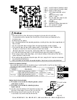
•  Fasten the   electric wire with the t erminal  screws  securely.  Imperfect connection m ay  cause a bnormal

  heating or fumes. 

• Use this controller according to the  rating and environmental conditions. Otherwise a bnormal heating or

  fumes may occur. 

• Do not touch the terminals while t he power is supplied to the controller, as this may cause electric shock.

• Do not disassemble or modify the controller, as this may cause electric shock or fumes.


Caution


• This instrument should be used in accordance with the specifications described in the manual. 

If it is not used according to the specifications, it may malfunction or cause fire. 

• Be sure to follow the warnings, cautions and notices. Not doing so could cause serious injury or accidents.

• The contents of this instruction manual are subject to change without notice. 

• This instrument is designed to be installed in a control panel. If not, measures must be taken to ensure 

that the operator cannot touch power terminals or other high voltage sections.   

• Be sure to turn the power supplied to the instrument OFF before cleaning this instrument. 

• Use a soft, dry cloth when cleaning the instrument.   

(Alcohol based substances may cause tarnishing or defacement of the unit) 

• As the display section is vulnerable, do not strike or scratch it with a hard object. 

• Any unauthorized transfer or copying of this document, in part or in whole, is prohibited. 

• Matsushita Electric Works, Ltd. is not liable for any damage or secondary damage(s) incurred as a result 

of using this product, including any indirect damage. 

• To pull out the inner assembly, release the hooks at the top and bottom of the instrument with thin, hard 

tweezers. (If the hooks are released too far, they may break, or IP 66 function could deteriorate.)   

Do not pull out the inner assembly except when repairing the instrument.) 
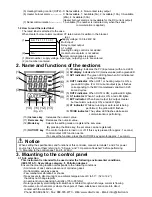
1. Model number 

1.1 Explanation of model number 

A  K  T  4       1                             


(1)  (2)  (3)  (4)  (5)  (6)  (7) 

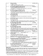
(1) Supply voltage ----------------------  1: 100 to 240V AC, 2: 24V AC/DC 

(2) Input type ----------------------------- 1: Multi-input (Thermocouple, RTD, DC current and DC voltage 


  can be selected by key operation) 

(3) Control output (OUT1) ------------   1: Relay contact, 2: Non-contact voltage, 3: DC current 

(4) Alarm output -------------------------  1: A1 output, 2: A1  A2 output 


(The alarm type and Energized /Deenergized can be selected   


by key operation) 


(When A2 output is applied, Heating/Cooling control cannot be   


added) 

Phone: 800.894.0412 - Fax: 888.723.4773 - Web: www.clrwtr.com - Email: [email protected]

Summary of Contents for KT4 series

Page 1: ...function or cause fire Be sure to follow the warnings cautions and notices Not doing so could cause serious injury or accidents The contents of this instruction manual are subject to change without notice This instrument is designed to be installed in a control panel If not measures must be taken to ensure that the operator cannot touch power terminals or other high voltage sections Be sure to tur...

Page 2: ...pressing the Mode key the set value can be registered 13 OUT OFF key The control output is turned on or off If this key is pressed for approx 1 second control output OFF function works To cancel the function press the OUT OFF key again for approx 1 second Notice When setting the specifications and functions of this controller connect terminals 1 and 2 for power source first then set them referring...

Page 3: ...ch the mounting brackets by the holes at the top and bottom of the case and secure the controller in place with the screws Fig 3 5 1 4 Wiring Warning Turn the power supply to the instrument off before wiring or checking it Working or touching the terminal with the power switched on may result in severe injury or death due to Electric Shock 75 45 0 5 0 45 0 5 0 45 0 5 0 n x 48 3 0 5 0 Warning As th...

Page 4: ...y contact output type use a relay according to the capacity of the load to protect the built in relay contact When wiring keep input wires thermocouple RTD etc away from AC sources or load wires to avoid external interference If A2 and Heater burnout alarm are applied together they share common output terminals Lead wire solderless terminal Use a solderless terminal with an insulation sleeve in wh...

Page 5: ...aling high limit value 5 2 Sub setting mode Character PV display Name Function Setting range Default value SV display AT setting Auto reset setting Selects auto tuning Perform or auto reset Perform If the auto tuning is cancelled during the process P I and D values revert to the previous value When auto tuning has not finished after 4 hours it is cancelled automatically Auto reset is cancelled in ...

Page 6: ...ing range High limit alarm Input span to input span 1 Low limit alarm Input span to input span 1 High Low limits alarm 0 to input span 1 High Low limit range alarm 0 to input span 1 Process high alarm Input range low limit value to input range high limit value 2 Process low alarm Input range low limit value to input range high limit value 2 High limit alarm with standby Input span to input span 1 ...

Page 7: ...ilable if Serial communication option is not added or if is selected during the Communication protocol selection No parity E ven parity Odd parity Stop bit selection 1 Selects the stop bit Not available if Serial communication option is not added or if is selected during the Communication protocol selection 1 or 2 5 4 Auxiliary function setting mode 2 Character PV display Name Function Setting ran...

Page 8: ...le if OUT2 is ON OFF action or if Heating Cooling control option is not added Air cooling oil cooling water cooling OUT2 high limit setting 100 Sets the high limit value of OUT2 Not available if OUT2 is ON OFF action or if Heating Cooling control option is not added OUT2 low limit value to 105 Setting higher than 100 is effective to DC current output type OUT2 low limit setting 0 Sets the low limi...

Page 9: ...ed timer setting Direct Reverse control action selection Selects either Reverse Heating or Direct Cooling control action Reverse Heating action Reverse Heating Direct Cooling AT bias setting 20 Sets bias value during PID auto tuning Not available if input type is DC current or DC voltage 0 to 50 0 to 100 or 0 0 to 50 0 0 0 to 100 0 Setting item not used This item is indicated when Serial communica...

Page 10: ...r to the instrument is supplied is indicated on the PV display while the function is working Once the control output OFF function is enabled the function cannot be released even if the power to the instrument is turned OFF and ON again To cancel the function press the key again for approx 1 second 5 7 Output manipulated variable MV indication Name function Output manipulated variable indication In...

Page 11: ...Set value Set the value with keys Not available if is selected during A2 type selection Reverts to the PV SV display Reverts to PV SV display Press the key Main setting mode Sub setting mode 5 PV SV display Control output OFF function or Auto Manual control function Press key for approx 1sec Output MV indication Explanation of key This means that if is pressed the set value is saved and the contro...

Page 12: ...o deviation Cycle action is performed according to deviation Cycle action is performed according to deviation Changes continuously according to deviation Unlit 4mA DC 7 6 7 6 7 6 7 6 7 6 7 6 7 6 7 6 7 6 7 6 7 6 7 6 7 6 7 6 7 6 7 6 7 6 7 6 SV setting Alarm action ON OFF Setting Load current Large Small Output Indicator Unlit Lit 3 5 3 5 Acts ON or OFF Heating Reverse action Cooling Direct action Co...

Page 13: ... with the keys Default value A2 action delayed timer PV SV Set value Set the value with the keys Not available if is selected during A2 type selection A2 hysteresis PV SV Set value Set the value with the keys Not available if is selected during A2 type selection AT bias PV SV Set value Set the value with the keys Available for thermocouple RTD input 2 Setting item not used PV SV Set value Do not s...

Page 14: ...h standby Low limit alarm with standby OFF ON OFF ON OFF ON Alarm action A1 hysteresis A1 hysteresis A1 hysteresis A1 set point A1 set point SV setting SV setting A1 set point A1 set point A1 set point SV setting A1 set point Standby functions in this section Cycle action is performed according to deviation OFF ON SV setting OFF ON 7 7 7 6 6 6 6 7 12V DC 6 7 12 0V DC 6 7 0V DC 6 7 20mA DC 6 7 20 t...

Page 15: ...ously according to deviation Non contact voltage output OUT1 DC current output OUT1 Non contact relay output OUT2 Indicator OUT1 Green Indicator OUT2 Yellow Lit Unlit Lit Unlit Cycle action is performed according to deviation 3 3 3 5 5 5 7 7 7 6 6 6 6 7 12V DC 6 7 12 0V DC 6 7 0V DC 6 7 20mA DC 6 7 20 to 4mA DC 6 7 4mA DC OFF ON OFF ON SV setting Heating action Cooling action Heating p band Coolin...

Page 16: ...ver is greater DC current Within 0 2 of each input span 1digit DC voltage Within 0 2 of each input span 1digit Input sampling period 0 25 seconds Input Thermocouple K J R S B E T N PL C W Re5 26 External resistance 100 or less However for B input External resistance 40 or less RTD Pt100 JPt100 3 wire system Allowable input lead wire resistance 10 or less per wire DC current 0 to 20mA DC 4 to 20mA ...

Page 17: ...ltage 100 to 240V AC 50 60Hz 24V AC DC 50 60Hz Allowable voltage fluctuation 100 to 240V AC 85 to 264V AC 24V AC DC 20 to 28V AC DC Power consumption Approx 8VA Ambient temperature 0 to 50 32 to 122 Ambient humidity 35 to 85 RH no condensation Weight Approx 200g External dimension 48 x 48 x 96 5mm W x H x D Material Flame resistant resin Case Color Ash gray Case Attached function Set value lock Se...

Page 18: ... located at 0 32 Power failure countermeasure The setting data is backed up in the non volatile memory Warm up indication After the p ower supply to the instrument is turned on the sensor input character an d temperature unit are indicated on the PV display and input range high limit value is indicated on the SV display for 3 seconds For DC current and voltage inputs the scaling high limit value i...

Page 19: ... working Press the key for approx 1 second to release the function is flashing on the PV display Thermocouple RTD or DC voltage 0 to 1V DC is burnt out Change each sensor How to check whether the sensor is burnt out Thermocouple If the input terminal of the instrument is shorted and if a value around room temperature is indicated the instrument is likely to be operating normally however sensor may...

Page 20: ...n ungrounded type sensor There may be equipment that interferes with or makes noise near the controller Keep equipment that interferes with or makes noise away from the controller The PV display is indicating Internal memory is defective Contact our agency or us 11 2 Key operation Problem Presumed cause and solution Unable to set the SV P I D proportional cycle or alarm setting The values do not c...

Reviews: