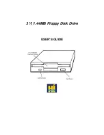
3.5" MICRO FLOPPY DISK DRIVES
3.5" MICRO FLOPPY DISK DRIVE
There are three types of micro floppy disk:
•
Double-Sided Double-Density (DSDD), formatted at 720 KB and used on 720 KB, 1.44 MB and
2.88 MB drives.
•
High-Density (HD), formatted at 1.44 MB and used on 1.44 MB and 2.88 MB drives.
•
Extra-Density (ED), formatted at 2.88 MB and used on 2.88 MB drives.
Bear the following rules in mind when using these disks.
•
The 2.88 MB drive can read and write to 720 KB and 1.44 MB disks; the 1.44 MB drive is compatible
with 720 KB disks.
•
Only MS-DOS release 5.0 can recognize 2.88 MB drives. The earlier DOS releases will recognize
the 2.88 MB drive as a 1.44 MB drive.
•
The 1.44 MB drive can format 720 MB disks by using the following formatting command:
Format/n:9/t:80, or /f:720 .
•
The 2.88 MB drive that uses MS-DOS 5.0 can format 720 KB and 1.44 MB disks with the simple
Format command.
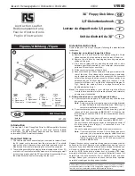
CONFIGURING DRIVE JUMPERS
Jumper settings on the floppy disk drives must not be changed from the default configuration
shown in the figures of the drives.
The only exception is the TM jumper (terminator), which must be removed when the 5.25"
drive is installed as the system’s second drive. However, this terminator must be present if
the 5.25" drive is the only one present in the system. The terminator is always present on
3.5" drives, and is soldered on the board.
The cross-over of some of the wires in the floppy disk’s signals cable determines the drive’s
physical address. The drive attached to the first connector is recognized as drive A, while
the drive attached to the second connector is recognized as drive B. Therefore there is no
need to make any jumper settings on the drive to determine its address. As a general rule,
all floppy disk drives must have the second jumper DS installed (in the ON position); in some
drives, this jumper is identified as DS1 since the jumpers are numbered DS0, DS1, DS2 and
DS3. In other drives, however, this jumper is identified as DS2 as the numbering of the
jumpers differs, such DS1, DS2, DS3 and DS4.
4
Peripherals - Pocket Service Guide
3.5" MICRO FLOPPY DISK DRIVES
4-1