background image

Panasonic HOME IoT 

Installation Guide

Warning

2020.7 ver.1.0

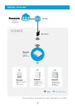
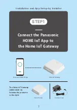
・  A Home IoT Gateway (MKG100C913) (referred to 

below as the “Gateway”) is required to use the 
Panasonic HOME IoT App. Ensure that your smart-
phone is connected to the same home wireless 
network (WLAN) as the Gateway.

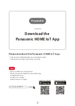
・  The App uses your Panasonic ID, 

 which you can receive by email from 

sender.pcpf.panasonic.com.

・  You may register only one Panasonic ID. However, 

there is no limit to the number of smartphones 
you can register to each Panasonic ID.

・ All images shown in this document are for 

illustrative purpose only.

Panasonic Life Solutions Europe

Panasonic Electric Works Europe AG

C o n t a c t :

Mon.-Thu./8:00〜12:00  13:00〜17:00

+49-89-45354-2745

Fri./8:00〜12:00  13:00〜14:00

Summary of Contents for HOME IoT

Page 1: ...e Gateway The App uses your Panasonic ID which you can receive by email from sender pcpf panasonic com You may register only one Panasonic ID However there is no limit to the number of smartphones you can register to each Panasonic ID All images shown in this document are for illustrative purpose only Panasonic Life Solutions Europe Panasonic Electric Works Europe AG C o n t a c t Mon Thu 8 00 12 ...

Page 2: ...asonic HOME IoT App P 6 Installation and App Setup by Installer P 7 P 30 App Setup by User P 31 P 37 Error Messages Important Notes and Reference Materials P 42 Error Messages Names of Components P 5 Other P 38 P 40 Important Notes Reference Materials P 43 P 44 P 44 2 ...

Page 3: ...r Measuring Unit internet WLAN Router H O M E 868MHz Panasonic WLAN Temperature Humidity Sensor Indoor Temperature Humidity Sensor Outdoor This system layout is representative of a system configuration as of July 2020 MKG100C913 MKG1500 DE MKG1301913 MKG1302913 3 ...

Page 4: ...eway to the internet Check the wireless signal strength to the Home IoT Gateway STEP2 STEP3 Setup the Power Measuring Unit STEP1 Create a Panasonic ID Initial registration to use the App STEP2 Installation Flow Installation and App Setup by Installer App Setup by User Preparation First Operation For details see the Panasonic HOME IoT Smartphone App Guide P 33 P 31 P 28 P 26 Setup the Temperature H...

Page 5: ...nit MKG1500 DE Temperature Humidity Sensor Indoor MKG1301913 Outdoor MKG1302913 Rear Front Front Rear Lower Side Upper Side Application LED Cover Front SET button CT connector Power terminals Low Battery Lamp Red Supplied Lithium Battery Connector Register Lamp Red Register Button Refresh Button Incoming Data Lamp Red Images depict the MKG1301913 Indoor model REGISTER LED 5 ...

Page 6: ...Phone users require an Apple ID to download the App Compatible OS versions iOS Version 11 or higher Android Version 5 0 or higher Please download the Panasonic HOME IoT App Note Panasonic HOME IoT Search Android users click here iPhone users click here App Store Download on the Google Play Get it on Download the Panasonic HOME IoT App Preparation 6 ...

Page 7: ...tup by Installer The Home IoT Gateway MKG100C913 includes the products to the right Home IoT Gateway AC adapter C type Home IoT Gateway Panasonic HOME IoT App Connect the Panasonic HOME IoT App to the Home IoT Gateway STEP1 7 ...

Page 8: ...ME IoT App to the Home IoT Gateway Plug in the AC adapter passing the cord through the cord stops 2 Reattach the cover 3 Installer Tasks Align the cover and body so that the cord passes through the cord aperture Note Cover Tab Tab Cord stops x3 Power plug AC adapter terminal Rear Cord aperture STEP1 8 ...

Page 9: ...p after plugging the AC adapter into the wall socket Plug the AC adapter into the wall socket 4 Connect the Panasonic HOME IoT App to the Home IoT Gateway Installer Tasks Once the start screen appears tap the Start button Tap to open the downloaded Panasonic HOME IoT App on your smartphone 5 Rear Status LED STEP1 9 ...

Page 10: ...ls and tap the Start button Installation follows the following process Connect your smartphone to the Gateway Register the Power Measuring Unit and sensors to the Gateway Connect the Gateway to the internet Tap the Installer settings button 6 Next proceed according to the instructions in the Panasonic HOME IoT App 7 STEP1 10 ...

Page 11: ...e Panasonic HOME IoT App to the Home IoT Gateway Installer Tasks Check that the Status LED on the rear of the Gateway is either lit or double or triple flashing and set WLAN AP switch 1 to the On posi tion The Gateway will immediately enter AP mode Once in AP mode the Application LED on the front of the Gateway will flash in orange Prepare the Gateway and check that the power is on Application LED 1...

Page 12: ...utton on the guidance screen tap your smartphoneʼs Home button to return to your home screen 2 Tap the Settings icon to open the settings screen 3 Under Wi Fi Settings select the Gatewayʼs SSID 4 Once the selected SSID has a check next to it indicating it is connected tap the Home button to return to your Home screen Now tap the app icon again to return to the Panasonic HOME IoT App 5 Tap the Push...

Page 13: ... connected to the Gateway 11 Connect the Panasonic HOME IoT App to the Home IoT Gateway Installer Tasks Go to the next step Tap Next button to proceed to the next step If not connedted to the Gateway properly an error screen will be displayed after tapping Next button STEP1 13 ...

Page 14: ...ing Unit MKG1500 DE CT 3 CT Cable 2m MKG1500 DE If solar generating or storage battery systems are to be monitored the optional product to the right is required 2 sets are required if both solar generating and storage battery systems are to be connected MKG1510 DE CT Sensor Option Setup the Power Measuring Unit STEP2 14 ...

Page 15: ...f the Power Measuring Unit must be carried out by a competent person If you are a compe tent person tap the OK button to continue Follow the instructions in the Panasonic HOME IoT App to install and register the Power Measuring Unit Tap the Power Measuring Unit button to start registration 1 Installation must be carried out by a competent person 2 Ensure the main breaker is opened before starting ...

Page 16: ...e wire along a path from the dedicated circuit breaker to the Power Measuring Unit 2 Prepare the dedicated circuit breaker end of the power wire and connect it to the dedicated circuit breaker 3 Remove 10mm of insulation from the Power Measuring Unit side of the power wire to match the unit s strip gauge Power wires must be solid core and sized at 2 5mm 4 Connect power wires to the power connectio...

Page 17: ...he CT Cable to the CT connector labelled MAIN on the Power Measur ing Unit Do not remove any other covers Once the CT cable is connected tapping the Next button displays a screen with an option for whether a solar generation or storage battery system is present Skip to 11for Yes or 12 for No Ensure that there is no branch wire between the CT measurement point and the power meter otherwise accurate...

Page 18: ...ire 1 Are the phases on the power terminal connection wires correct 2 Are power terminal wires on the correct position and fully inserted 3 Is the CT installation position and direction correct 4 Is the CT Cable installed in the correct location 5 Turn the dedicated power connection breaker and main breaker on and check the Power Measuring Unit power LED lights up Once checks are complete tap the ...

Page 19: ...osition 14 Setup the Power Measuring Unit Installer Tasks Check the Status LED on the rear of the Gateway is either lit or repeats a double or triple flash and set WLAN AP switch 1 to the OFF position and the back to the ON position The Gateway will immediately enter AP mode Once in AP mode the Application LED on the front of the Gateway will flash in orange Application LED 1 2 3 4 O N Status LED Re...

Page 20: ...button on the guidance screen tap your smartphoneʼs Home button to return to your home screen 2 Tap the Settings icon to open the settings screen 3 Under Wi Fi Settings select the Gatewayʼs SSID 4 Once the selected SSID has a check next to it indicating it is connected tap the Home button to return to your Home screen Now tap the app icon again to return to the Panasonic HOME IoT App 5 Tap the Pus...

Page 21: ... After completing the above process tap the Check button to confirm registration Application LED 17 Put the Gateway into registration mode Check that the Application LED is flashing in orange Tap the Activate Registration Mode at the bottom of the screen to enter the Gatewayʼs device registration mode Tap the Next button to move to the next step The smartphone is successfully connected to the Gatewa...

Page 22: ... figures are displayed Here we confirm that the measurements being taken look correct If an abornal value is shown tap the In event of an abnormal value button to restart the process for Step If PV is installed negative value is displayed while generating A storage battery will display as a positive number while charging and negative while discharging Tap the Everything is normal button STEP2 3 22 ...

Page 23: ...re Humidity Sensor MKG1301913 MKG1302913 contains the following products Temperature Humidity Sensor Lithium battery Installation and App Setup by Installer o p t i o n Setup the Temperature Humidity Sensor STEP3 23 ...

Page 24: ...umidity Sensor Installer Tasks Tapping the Next button on the final page of displays the screen to the left Insert the lithium battery which came with the Temperature Humidity Sensor Tap the Next button Tap the Activate regis tration mode button to start the Gatewayʼs device registra tion mode Tap the Temperature Humidity Sensor button to start registration Insert the lithium battery into the Tempe...

Page 25: ...tiple Temperature Humidity Sensors are to be used repeat steps to for each Install the device in the location where temperature and humidity measurements are to be taken 6 Setup the Temperature Humidity Sensor Installer Tasks Example positioning of Temperature Humidity Sensor MKG1301913 Temperature Humidity Sensor Note The name of the Temperature Humidity Sensor is used as the device ID Note STEP3...

Page 26: ...Installation and App Setup by Installer Check Home IoT Gateway Check the wireless signal strength to the Home IoT Gateway STEP4 26 ...

Page 27: ...the screen If there are connec tion errors adjust the position of the Gateway an try again Note Check the wireless signal strength to the Home IoT Gateway Installer Tasks Confirm the output on the screen to the left If there are no problems tap the Everything is normal button Please be patient as the checking process takes several minutes Once all devices are installed tap the Settings Complete but...

Page 28: ...Installation and App Setup by Installer internet WLAN Router Home IoT Gateway Connect the Home IoT Gateway to the internet STEP5 28 ...

Page 29: ...utton tap There is a WPS button If there is no WPS button tap There is no WPS button The position and length of press required differs between Router model Please check your WLAN Router specification Note Connect the WLAN Router to the Gateway 1 Check whether your WLAN Router has a WPS button 2 If there is a WPS button If there is no WPS button Installer Tasks Tap the Connect button STEP5 29 ...

Page 30: ...outer again by following the procedure below Note Check the Status LED on the rear of the Gateway after 2 minutes If the Status LED is lit the Gateway is success fully connected to the WLAN Router Tap the LED is on button to complete WLAN setup 1 Turn the WLAN AP switch on the rear of the Gateway switch 1 to the off position then back to the on position 2 Check that the Gatewayʼs Application LED fla...

Page 31: ...App Setup by User Create a Panasonic ID STEP1 31 ...

Page 32: ...d tap Forgot password at the bottom of the screen to reset the password Note There is no need to create a new ID Simply enter your existing ID and password to login Tap I donʼt have a Panasonic ID The website for creating an ID will open Enter the required details to create an ID If you have a Panasonic ID If you donʼt yet have a Panasonic ID User Tasks STEP1 32 ...

Page 33: ...Initial registration to use the App App Setup by User internet Panasonic Cloud Server Home IoT Gateway STEP2 33 ...

Page 34: ...gin Read the privacy notice and tap the Understood button to continue If you do not agree with the terms you will be unable to use the service Note Login with your Panasonic ID and password 1 Confirm the Privacy Notice 3 Agree to the Terms of Use by tapping the Agree button 2 User Tasks STEP2 STEP1 34 ...

Page 35: ...phone is connected to the same home wireless network WLAN as the gateway Tap the Search button Once registration is complete tap the Next button Check that the Gatewayʼs Application LED flashes in orange and tap the Scene Control Button on top of the Gateway The LED will light in orange for 5 seconds to indicate success Registering the Gateway with the Server 4 Application LED Tap the Next button S...

Page 36: ... and 1990 Before 1950 Enter your country postcode and the age of your home 5 6 User Tasks Tap the Register button If a Temperature Humidity Sensor MKG1301913 MKG1302913 is installed this will be used to analyse ventilation timings Confirm the list of devices registered with the Gateway STEP2 If a Temperature Humidity Sensor is listed in the registered devices select its installed location After sel...

Page 37: ...e electricity bill and energy plan for the previous year Your annual electricity bill and energy plan details can be found on bills from your energy provider Refer to your bill when entering these details 7 Initial setup complete 8 Enter details on your electricity usage User Tasks Remember to include standing charges in the amount of the annual bill Energy screen Air quality screen Tap the Regist...

Page 38: ...Add delete replace a device App Setup by User Other 38 ...

Page 39: ... here if the Gateway is to be replaced due to a breakdown Add a device 4 1 Gateway settings 4 2 Displays information on the registered Power Measuring Unit Start here to replace or remove a Power Measuring Unit Power Measuring Unit settings 4 3 Displays information on registered devices in each room Start here to edit a registered device Humidity Sensor settings 4 4 Add a device 4 1 Select the typ...

Page 40: ...screen instructions Temperature Humidity Sensor settings 4 4 Refresh Button Incoming Data Lamp Red Tap the delete symbol to delete Tap the Replace button and follow the on screen instructions to configure Deleting a Temperature Humidity Sensor Hold the Refresh Button on the Temperature Humidity Sensor for 2 seconds and check that the Incoming Data Lamp flashes in red Then tap the delete symbol to de...

Page 41: ...Error Messages Important Notes and Reference Materials Error Messages Important Notes Reference Materials P 42 P 43 P 44 P 44 41 ...

Page 42: ... 35 U Connection problem between the App and server Authentication error on login Smartphone App could not startup Smartphone App could not open an Internet browser Gateway not responding to UpnP M Search Wireless device registration error Power Measuring Unit Temperature Humidity Sensor Could not acquire Gateway device ID Failed to connect to server Gateway failed to enter registration mode Anoth...

Page 43: ... inside a steel cabinet or karaoke box The device is fixed to a metal wall The signal is blocked by the person operating the device There is a domestic electrical device such as a microwave or computer or an OA device within 2m of the device A bell or motor device operated with direct current is close to the device A mobile telephone or PHS telephone is used close to the device A microwave therapy ...

Page 44: ...ible A malicious third party may intentionally intercept your wireless communi cations and access content such as ID password images or email addresses Unauthorised access A malicious third party may access your personal network without permis sion and take actions such as accessing personal or confidential information information leakage impersonating a specific individual and providing fraudulent ...

Reviews: