background image


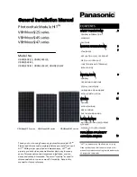
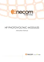
General Installation Manual 
Photovoltaic Module HIT

®


HIT Power 240S series 
HIT Power 235S series 
HIT Power 230S series 

 
Thank you for choosing Panasonic HIT

®

. Please 

read  this  manual  completely  before  installation 
or use of Panasonic PV(photovoltaic) modules. 
With  proper  operation  and  maintenance, 
Panasonic  HIT

®

  will  provide  you  with  clean, 

renewable solar electricity for many years. This 
manual 

contains 

important 

installation, 

maintenance  and  safety  information.  The  word 
“module” as used in this manual refers to one 
or more PV modules.  Retain this manual for 
future  reference.  The  module  is  considered  to 
be in compliance with UL 1703 only when the 
module is mounted in the manner specified by 
the mounting instructions below. 
 
SANYO is part of the Panasonic Group and is 
in  charge  of  the  manufacturing  process  for 
Panasonic HIT

®


Model No. 

HIT Power 240S 


VBHN240SA11 and 11B 

HIT Power 235S 


VBHN235SA11 and 11B 

HIT Power 230S 


VBHN230SA11 and 11B


Contents 

 
Please read before installation 

Safety Precautions 


General Information 


:3 


Warning 


:3 


Cautions 


:3 


General Safety   


:3 


UL Listing Information 


:3 


Installation 


General 


:4 


Notes on Installation 


:4 


Operating Conditions 


:5 


Specifications 


Note on Specifications 


:5 


Mechanical Loading 


:5 


Wiring 


General 


:5 


Module Wiring   


:5 


Array Wiring   


:5 


Earth Ground Wiring 


:5 


Grounding Locations 


:6 


Grounding Methods 


:6 


Module Terminations 


:8 


Junction Box and Terminals 

:8 


Conduit 


:8 


Bypass Diodes 


:8 


Maintenance 


:8 


Disclaimer of Liability 


:8 


Customer Services    


:8 


“HIT”  is  a  registered  trademark  of  Panasonic 
Group. 
 
Other product and service names listed in this 
manual are trademarks or registered trademarks 
of their respective companies. 


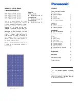
VBHNxxxSA series 

Summary of Contents for HIT Power 230S Series

Page 1: ...O is part of the Panasonic Group and is in charge of the manufacturing process for Panasonic HIT Model No HIT Power 240S VBHN240SA11 and 11B HIT Power 235S VBHN235SA11 and 11B HIT Power 230S VBHN230SA11 and 11B Contents Please read before installation Safety Precautions General Information 3 Warning 3 Cautions 3 General Safety 3 UL Listing Information 3 Installation General 4 Notes on Installation...

Page 2: ...ised Content New Edition 2013 4 19 2nd Edition 2015 3 18 1 System Fire Class Rating 2 Trademark 3 Front cover Grounding 1 Addition of System Fire Class Rating 2 Explanation of trademark 3 According to UL1703 Edition 3 Revision date 2014 11 18 ...

Page 3: ...ass diodes Do not touch a module unnecessarily The glass surface and frames get hot There is a risk of burn CAUTIONS Use a module for its intended purpose only Do not treat the back sheet frame or front surface with paint or adhesives to avoid reducing its functionality damage and causing inoperable conditions and other unknown troubles Do not insert PV cable between back side and mounting structu...

Page 4: ...ions see figure 1 and below Provider UniRac Inc Part number SolarMount Clamps type Top Mounting Clamps Clamp size Mid clamp and End clamp C size Unirac Part No 302003 302101 Width 1 5 38 mm Thickness 0 12 3 mm Torque range 16N m to 20N Material Aluminum Alloy 6005 T5 6105 T5 6061 T6 If another clamp except Unirac is used it must have material alloy designations physical dimension and capture area ...

Page 5: ...hock To avoid the hazard of electric shock and sparks please connect each cable after confirming the polarity of them is correct Cable conduits should be used in locations where the wiring is inaccessible to children or small animals Module Wiring The number of modules that can be wired in series is recommended to be ten 10 or fewer If connecting eleven 11 modules in series check local temperature...

Page 6: ...bolts star washers spilt ring lock washers flat washers and the like is used to attach a listed grounding bonding device the attachment must be made in conformance with the grounding device manufacturer s instructions Common hardware items such as nuts bolts star washers lock washers and the like have not been evaluated for electrical conductivity or for use as grounding devices and should be used...

Page 7: ...This will terminate the wire For more information please refer to Instruction sheet issued by Tyco Electronics Using a Grounding Clip with bolt and nut Use Tyco Electronics 1954381 2 as grounding clip As shown in figure 3 7 place the grounding clip onto the module frame Thread the hex nut onto the end of the screw then using a 3 8 in wrench tighten the nut Recommended torque value in tightening bo...

Page 8: ...ration use or maintenance by using this manual Panasonic assumes no responsibility for any infringement of patents or other rights of third parties which may result from use of modules No license is granted by implication or under any patent or patent rights The information in this manual is believed to be reliable but does not constitute an expressed and or implied warranty The return of any modu...

Page 9: ...e frame and the flat washer diameter must be greater than the cup washer diameter If using a brass cup washer a flat washer must be inserted between the cup washer and module frame and the flat washer diameter must be greater than the cup washer diameter Cup washer Terminal cup Stainless steel or brass Star washer Stainless steel Flat washer Stainless steel Flat washer Stainless steel Spring washe...

Page 10: ...meter 5 2mm Flat washer Stainless steel Thickness not less than 0 037 0 94 mm Diameter not less than 0 75 19 05 mm Grounding Lug Bolt Stainless steel 8 10 M5 Nut Stainless steel Copper wire Set screw Stainless screw Star washer Stainless steel Length not less than 0 63 16 mm not more than 0 78 20 mm Self tapping machine screw Stainless steel Copper wire Frame Longer side Glass Backsheet Grounding ...

Page 11: ...ound holes illustrated in Figure 3 1 Grounding Clip Assemblies Tyco Electronics 1954381 2 Glass Backsheet Frame Longer side Grounding hole 0 205 diameter 5 2mm Grounding Clip 8 32 Screw Stainless steel Nut Stainless steel Copper wire Length not less than 0 63 16 mm not more than 0 78 20 mm Copper wire Frame Longer side Glass Backsheet Grounding hole 0 165 diameter 4 2mm Grounding Clip Self tapping...

Page 12: ... System Voltage Voc 600 600 600 Factory Installed Bypass Diodes 3 3 3 Maximum series fuse A 15 15 15 Mechanical Specifications Length mm inches Width mm inches Frame Depth mm inches Weight kg pounds 35 1 4 15 33 1 Electrical Specifications 1580 62 2 798 31 4 SPECIFICATIONS Figure 2 Dimensions Dimensions All HIT Power S Models VBHNxxxSA11VBHNxxxSA11 Note A module should be installed on a mounting s...

Reviews: