


1 SCHEMATIC DIAGRAM
2
2 WIRING CONNECTION DIAGRAM
2
3 DISASSEMBLY/ASSEMBLY INSTRUCTIONS
3
©
2003 Matsushita Electric Works Ltd. All rights
reserved. Unauthorized copying and distribution is a
violation of law.
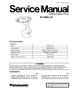
EY6506-U1
4 TROUBLESHOOTING GUIDE
5
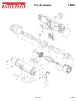
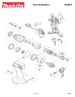
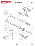
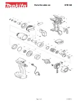
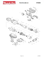
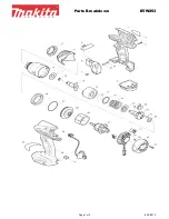
5 EXPLODED VIEW
7
6 REPLACEMENT PARTS LIST
8
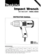
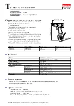
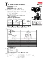
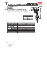
Cordless Impact Driver
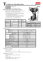
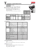
SPECIFICATIONS
CONTENTS
Page
Page
ORDER NO.PTD0310U39C1
F16