


•
WARRANTY SERVICE CARD
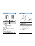
WARRANTY CARD
PRODUCT NAME
Wireless Transceiver System
PERIOD
MODEL NAME
CCR24GEN
1 YEAR
From the
date of
purchase.
PURCHASE DATE
. . 200_
WARRANTY PERIOD
. . 200_
CUSTOMER’S ADDRESS :
NAME :
TEL :
AGENT’S ADDRESS :
NAME :
TEL :
* Be sure to fill in blanks when the unit is sold
We grant 1 year warranty on the product commencing on the
date of purchase. Within the warranty period, the manufacturer
will correct, free of charge, any defect in the unit resulting from
faults in materials or workmanship, either by repairing or
replacing the entire unit as manufacturer may choose.
This warranty does not cover: damages due to improper use,
normal wear and tear, or defects that have a negligible effect on
the value or operation of the unit. The warranty is void if repairs
are undertaken by unauthorized persons and if original Trinus
parts are not used.
To obtain service within the warranty period, bring in or ship the
complete unit with your purchase invoice to a Trinus Customer
Service Center.
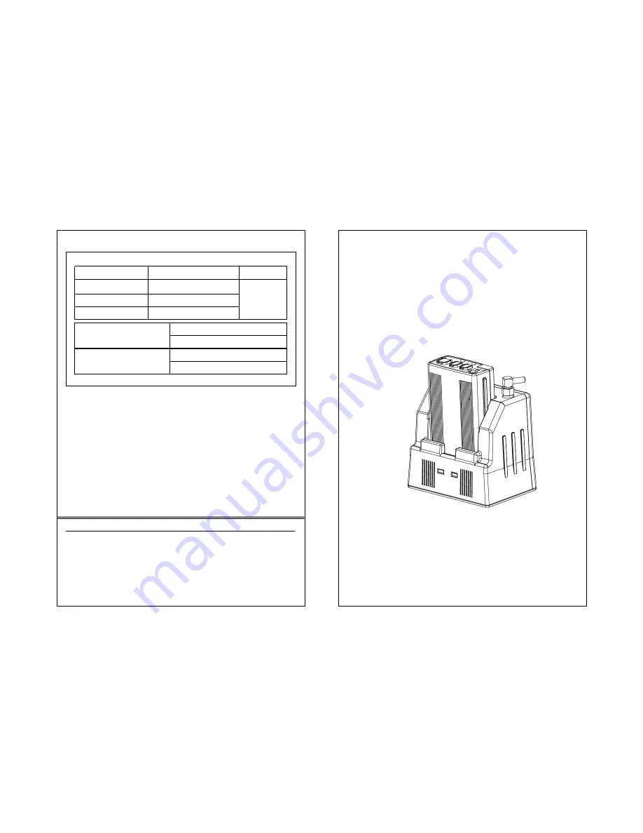
User’s Guide
●
Read this user’s guide carefully for safe operation and proper
use of the product .
CCR24T
CCR24R
WIRELESS TRANSMITTER SYSTEM


