Installation Guide
Network Camera
Model No.
BL-C111
(Wired Type)
BL-C131
(Wireless/Wired Type)
This manual is written for both the BL-C111 (Wired Type) and BL-C131 (Wireless/Wired Type). Available features and operations vary slightly
depending on the model. You can confirm the model no. of your camera by checking the model no. printed on the front of the camera.
Please read the included Important Information before proceeding.
Complete Operating Instructions and all other documentation can be found on the included CD-ROM.
• This document (Installation Guide) explains how to physically connect the camera to the power supply and network, as well how to mount or place the
camera for regular use.
• The
Setup Guide
describes how to set up the camera so that it can be accessed using a PC.
• Refer to the
Operating Instructions
on the
CD-ROM
for details regarding the camera's features.
• Refer to the
Troubleshooting Guide
on the
CD-ROM
if you have any problems configuring or using the camera.
Abbreviations
• UPnP is the abbreviation for “Universal Plug and Play”.
• The Network Camera is referred to as “the camera” in this document.
• The Setup CD-ROM is referred to as “the CD-ROM” in this document.
Installation Procedure Overview
The following is an overview of the steps required to install and setup the camera. All steps are explained in this document unless otherwise noted.
Preparation
1.
Confirm the following items are included in the camera’s packaging.
2.
You will need the following additional items to install and configure the camera.
– a PC (see the system requirements in the Important Information document)
– a LAN cable (CAT-5 straight cable)
– a router
Preparation
Confirm that you have all the
items required for installation.
Camera Diagram
Make sure you know the names
of the camera’s physical
features.
Connections
Connecting the camera to your
network and to the power outlet.
Setup
Setting up the camera
(described in the included Setup
Guide). This involves configuring
the camera so that it can be
accessed from a PC.
Mounting
Mounting or placing the camera.
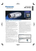
Main Unit (1 pc.)
The appearance of your camera
depends on which model you
have purchased.
Screw A (2 pcs.)
Order No. PQHE5004X
Used for wall mounting the
camera.
Washer S (2 pcs.)
Order No. XWG35FJ
Used when mounting the camera.
AC Adaptor (1 pc.)
Order No. PQLV206CEY
(Cord Length: About 3 m)
For use in countries/areas
other than the United Kingdom
Screw B (1 pc.)
Order No. XTB4+20AFJ
Used for securing the safety wire
to the wall.
Washer L (1 pc.)
Order No. XWG4F16VW
Used when securing the safety
wire to the wall.
Order No. PQLV206EY
(Cord Length: About 3 m)
For use in the United Kingdom
Safety Wire Screw (1 pc.)
Order No. PQHD10110Z
Used for securing the safety wire
to the camera.
Important Information (1 pc.)
Installation Guide
(this document) (1 pc.)
Setup Guide (1 pc.)
Safety Wire (1 pc.)
Order No. PQME10080Z
Used to secure the camera when
wall mounting it.
Setup CD-ROM (1 pc.)
Order No. PNQC1048Z
Contains the Setup Program needed to configure the camera,
as well as the camera’s documentation.*
*See the included Important Information for a description of each document.
BL-C111
BL-C131
© Panasonic System Networks Co., Ltd. 2007
PQQX15803YA
KK0107CM1020 (CE)
Please read this document before using the product, and save this document for
future reference.
• This document can be found on the included CD-ROM. English, French, German,
Italian, Spanish, Russian, Simplified Chinese, Korean, Danish and Swedish versions
are included.
Indoor Use Only