background image

Printed in Japan
Gedruckt in Japan
Imprimé au Japon
Stampato in Giappone
Impreso en Japón

Напечатано в Японии

在日本印制

VQTB0135 

F0806Y1116 

D

Matsushita Electric Industrial Co., Ltd.

Web Site: http://panasonic.net

E

FRANÇAIS

DEUTSCH

ENGLISH

IT

ALIANO

ESP

AÑOL

中  文

РУССКИЙ

Before attempting to connect, operate or adjust this product,  

please read these instructions completely.
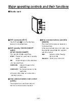
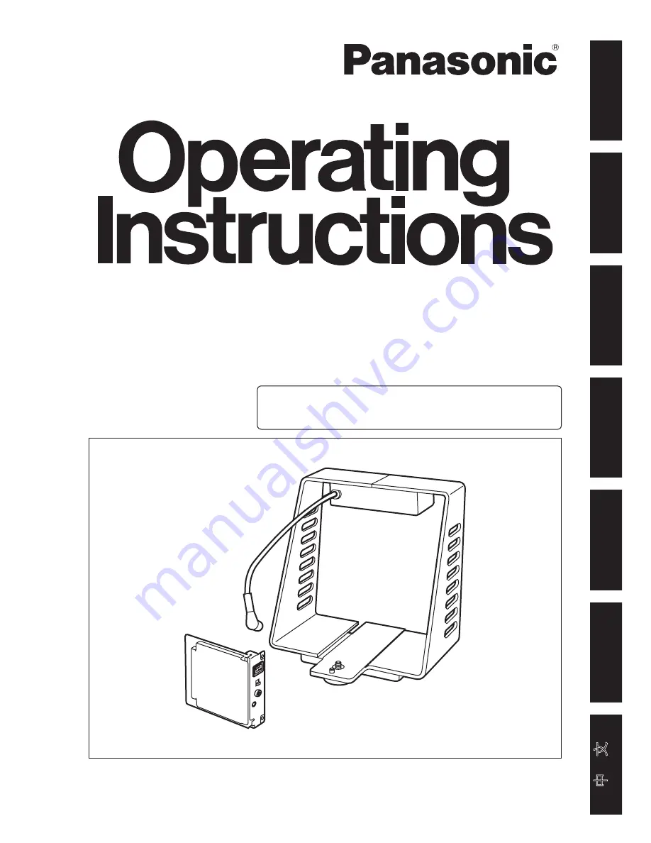
Studio Card

AW-PB305AL

This product consists of an studio card and an 
interface bracket.

松下电器产业株式会社

Web Site: http://panasonic.net

Summary of Contents for AW-PB305

Page 1: ...ISH ITALIANO ESPAÑOL 中 文 РУССКИЙ Before attempting to connect operate or adjust this product please read these instructions completely Studio Card AW PB305AL This product consists of an studio card and an interface bracket ...

Page 2: ...ING LIQUIDS AND DO NOT PLACE ANY LIQUID CONTAINERS ON TOP OF THE EQUIPMENT CAUTION TO REDUCE THE RISK OF FIRE OR SHOCK HAZARD AND ANNOYING INTERFERENCE USE THE RECOMMENDED ACCESSORIES ONLY CAUTION TO REDUCE THE RISK OF FIRE OR SHOCK HAZARD REFER CHANGES OF SWITCH SETTINGS INSIDE THE UNIT TO QUALIFIED SERVICE PERSONNEL DO NOT REMOVE PANEL COVERS BY UNSCREWING To reduce the risk of electric shock do...

Page 3: ...ctly will help to save valuable resources and prevent any potential negative effects on human health and the environment which could otherwise arise from inappropriate waste handling Please contact your local authority for further details of your nearest designated collection point Penalties may be applicable for incorrect disposal of this waste in accordance with national legislation For business...

Page 4: ... camera 8 Mounting the viewfinder on a bracket 8 Connections 9 When configuring a system with the remote control unit 9 When configuring a system with the remote operation panel 10 Setting and changing of menu items 11 Performing the settings 11 Optional card settings submenu 13 Appearance 14 Studio card 14 Interface bracket 15 Specifications 16 Accessories Adjuster plug M6 M3 1 Screws 6 mm 2 Scre...

Page 5: ...era on the interface bracket makes it possible for a viewfinder and or inter communications headset to be used and thus enable the camera to be used as a studio camera Notes The AW PB305A cannot be installed to the following models AW RP605 AW PB605 When the studio card unit is to be discarded at the end of its service life ask a specialized contractor to dispose of it properly in order to protect...

Page 6: ...r the AW VF64 VIDEO ON Outputs images to the viewfinder VIDEO OFF No images appear on the viewfinder The AW VF64 does not come with a standby function 3 Inter communications level control LEVEL This adjusts the sound level output to the inter communications headset 4 Inter communications jack M3 INCOM The inter communications headset is connected here If the plug diameter does not match use the ad...

Page 7: ...is is connected to the EVF connector 1 on the studio card 8TALLY input connector TALLY IN This is the tally control external input connector OPEN TALLY OFF SHORT TALLY ON When using the AW CB400 remote operation panel and AW CA50T8G control cable for connecting to the convertible camera connect the TALLY cable of the AW CA50T8G to this connector Note Do not connect EVFs to EVF connectors 1 and 2 5...

Page 8: ...cover 4 Align the studio card with the guides and insert it Ensure the card is fully inserted 5 Firmly tighten the 2 screws 6 mm to the optional card slot 6 Firmly secure the rear panel with the 4 screws 8 mm Note If the screws are misplaced use the extra screws supplied with this product Before installing the studio card Release the static carried in the body of the person to perform the installa...

Page 9: ... is supplied to the viewfinder onto the top of the interface bracket using the 2 screws provided Mount the base securely so that it is not unsteady 4 Slide the viewfinder onto the mounting base and tighten the fixing knob to secure it firmly 5 Connect the viewfinder cable to the EVF connector 1 or 2 on the interface bracket 6 Connect the EVF cable from the interface bracket to the EVF connector on...

Page 10: ...nect the remote control unit to the convertible camera Power to the camera is supplied from the remote control unit Viewfinder WV VF65B AW VF80 AW VF64 etc Convertible camera AW E350 AW E650 AW E655 AW E750 AW E860 etc Video monitor Remote control unit RCU WV RC700A WV RC550 AW RC600 etc Composite signals Coaxial cable RCU cable AW CA50A26 Inter communications headset When configuring a system wit...

Page 11: ...h is an optional accessory for the power supply Inter communication between the remote operation panel and studio card is not possible When configuring a system with the remote operation panel Viewfinder WV VF65B AW VF80 AW VF64 etc Convertible camera AW E350 AW E650 AW E655 AW E750 AW E860 etc Video monitor Remote operation panel AW CB400 etc Control cable AW CA50T8G TALLY cable AC adapter AW PS5...

Page 12: ...his is displayed when the convertible camera is used to perform the settings Option Card 2 is displayed on the menu when the optional card has been plugged into the optional card slot of the additional card box MENU switch ITEM AWC switch YES ABC switch NO BAR switch MENU switch DATA YES UP switch ITEM UP switch ITEM DOWN switch DATA NO DOWN switch Camera settings to match the system configuration...

Page 13: ...ENU or ITEM AWC switch to move the flashing to the desired setting item then press the YES ABC or NO BAR switch to change the setting When performing the settings with the remote control unit AW RC600 Press the ITEM UP or ITEM DOWN switch to move the flashing to the desired setting item then press the DATA YES UP or DATA NO DOWN switch to change the setting 4 Return to filming mode When performing...

Page 14: ...le when ON has been selected for the Zebra indicator 1 setting 3Safety zone 1 to 4 OFF This selects the type of safety zone that is displayed in the viewfinder If OFF is selected a safety zone will not be displayed Note The safety zone and the center marker reflect the electrical positions which may differ from the optical positions The inner frame and the outer frame are approximately 90 and 95 r...

Page 15: ... 14 E ENGLISH Appearance Unit mm Studio card 91 21 5 70 96 ...

Page 16: ... 15 E 183 190 Appearance Unit mm Interface bracket 141 30 50 ...

Page 17: ...nd composite signals brightness 1 0 V P P EVF connector 2 6 pin round composite signals brightness 1 0 V P P TALLY input connector BNC Switch control functions Studio card EVF standby VIDEO ON OFF switch WV VF65B AW VF80 ST BY ON AW VF64 VIDEO ON VIDEO OFF Inter communications level control Menu screens Zebra indicator ON OFF Level 70 to 110 Safety zone 1 2 3 4 5 OFF EVF output Y CVBS Weight and d...

Reviews: