background image

POWER

ALARM

F1

F2

F3

F4

F5

KEY

DSK

PinP

AUX

CLN

PVW

PGM

1

2

USER

AUX SOURCE

AUX BUS DELEGATION

1

2

3

4

5

6

7

8

9

10

AUX

PGM/A

PST/B

BKGD PATT

KEY PATT

FUNC

N/R

R

WIPE DIRECTION

WIPE PATTERN / FUNCTION

ON

WIPE

SQ

SL

3D

POSITIONER

Z

ON

FTB

PinP

DSK

CUT

AUTO

MIX

WIPE

BKGD

KEY

MIX

WIPE

PAGE

   AMB:FILL / GRN:SOURCE

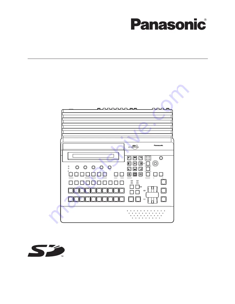
Multi-format Live Switcher  AV-HS400

11

TIME

WIPE

COLOR

KEY

CHR KEY

FREEZE

DSK

PinP

IN/OUT

MEMORY

XPT

SYSTEM

1

2

3

4

5

6

7

8

9

10

12

Operating Instructions

Multi-format Live Switcher

Model No.  

AV-HS400N

Before operating this product, please read the instructions carefully and save this manual for 
future use.

Printed in Japan 

VQTB0308-3

Summary of Contents for AVHS400N - MULTI FORMAT LIVE SWITCHER

Page 1: ...ITIONER Z ON FTB PinP DSK CUT AUTO MIX WIPE BKGD KEY MIX WIPE PAGE AMB FILL GRN SOURCE Multi format Live Switcher AV HS400 11 TIME WIPE COLOR KEY CHR KEY FREEZE DSK PinP IN OUT MEMORY XPT SYSTEM 1 2 3 4 5 6 7 8 9 10 12 Operating Instructions Multi format Live Switcher Model No AV HS400N Before operating this product please read the instructions carefully and save this manual for future use Printed...

Page 2: ...energy and if not installed and used in accordance with the instruction manual may cause harmful interference to radio communications Operation of this equipment in a residential area is likely to cause harmful interference in which case the user will be required to correct the interference at his own expense Warning To assure continued FCC emission limit compliance the user must use only shielded...

Page 3: ... 11 Only use attachments accessories specified by the manufacturer 12 Use only with the cart stand tripod bracket or table specified by the manufacturer or sold with the apparatus When a cart is used use caution when moving the cart apparatus combination to avoid injury from tip over 13 Unplug this apparatus during lightning storms or when unused for long periods of time 14 Refer all servicing to ...

Page 4: ...key material 29 3 3 3 Key transitions 30 3 3 4 Key preview 31 3 3 5 Adjusting the luminance key and linear key 31 3 3 6 Adjusting the chroma key 32 3 3 7 Key decorations 35 3 3 8 Masking the key signals 36 3 4 PinP picture in picture 37 3 4 1 Selecting the PinP material 37 3 4 2 PinP transitions 37 3 4 3 PinP preview 37 3 4 4 PinP adjustments 38 3 4 5 PinP decorations 39 3 4 6 Trimming settings 40...

Page 5: ...ng the DVI output signals option 69 4 10 Setting the ancillary data 70 5 System settings 71 5 1 Selecting the video format 71 5 2 Setting the crosspoints 72 5 2 1 Assigning signals to the crosspoints 72 5 2 2 Setting the crosspoint switching 73 5 3 Button assignments 74 5 3 1 Setting the user buttons 74 5 3 2 Setting the FTB button 74 5 4 Setting the date and time 75 5 5 Network settings 76 5 6 Ot...

Page 6: ... SD formats 480 59 94i and 576 50i as well as the DVI I format are supported for the signals Multi view display function This unit enables up to 10 lines of program video PGM preview video PVW and input video signals to be displayed altogether on a single screen at the same time Frame synchronizer system and external synchronization system supported A high performance 10 bit frame synchronizer is ...

Page 7: ... gently Then after wiping the product with a moist cloth wipe it again with a dry cloth Avoid using benzine paint thinners and other volatile fluids If a chemical cleaning cloth is to be used carefully read through the precautions for its use Caution Precaution to be observed during production This product s image switching and image effect functions can be used to produce images which flicker rap...

Page 8: ...rear panel is set to ON while power is supplied to the AC power input socket It goes off when the power switch _ is set to OFF 2Alarm indicator ALARM This indicator lights when the fan is stopped or there is a problem with the power supply such as a drop in voltage When an alarm has occurred the type of trouble can be checked on the System Alarm 6 14 menu In addition an alarm message is displayed ...

Page 9: ...ternately When the key fill bus is selected the indicator of the button lights in amber and when the key source bus is selected it lights in green DSK Press this button to switch the AUX bus crosspoint buttons to the DSK fill bus or DSK source bus Each time the button is pressed the DSK fill bus or DSK source bus is selected alternately When the DSK fill bus is selected the indicator of the button...

Page 10: ...e pages selected by the key transitions while the indicator of the KEY PATT button is lighted The WIPE SQ squeeze SL slide or 3D 3 dimensions LED lights FUNC button When this button is pressed its indicator lights in amber When a wipe pattern selector button 8 is pressed while the indicator of the FUNC button is lighted the setting menu indicated below the button is displayed on the LCD screen TIM...

Page 11: ...11 1 Functions in each area 1 4 User button area 1 2 USER User buttons USER 1 USER 2 These are used to allocate some functions of the menu settings to the USER 1 button and USER 2 button See 5 3 1 ...

Page 12: ... the indicator goes off and the de selected status is established When the BKGD button and KEY button are pressed at the same time both buttons are set to the selected status KEY ON tally LED This lights in red when the key ON status is established A MIX WIPE selection status tally LEDs These light up to indicate whether MIX or WIPE has been selected when background transitions or key transitions ...

Page 13: ...or fade out of the picture in picture for the transition time which has been set H DSK button This button is used to execute fade in or fade out of downstream key for the transition time which has been set I Wipe direction selection buttons These buttons are used to select the direction in which to wipe for executing background transitions When the indicators are off Wiping proceeds in the normal ...

Page 14: ... 5 WIPE WIPE menu Border sub menu 1 5 Wipe area WIPE 5 WIPE menu WIPEPos sub menu 3 5 BKGD or KEY SQ 5 WIPE menu SQPos sub menu 4 5 BKGD or KEY MRotary encoders F1 to F5 These are used to set the parameters displayed on the menus LCD screen or external monitor For details on the operations refer to the sections in 3 Basic operations F1 Rotate this rotary encoder to switch the sub menu F2 to F5 Rot...

Page 15: ...lockwise and reduced by rotating it counterclockwise Selected area size adjustments size increased by rotating the encoder clockwise and reduced by rotating it counterclockwise Switch Hold switch down to restore initial values X Y Z Hold switch down to restore initial values X Y Hold switch down to restore initial values X Y Z Valid menu All PinP menus WIPE WIPEPos WIPE SQPos CHR KEY Auto only whe...

Page 16: ...TAL OUTPUTS PGM OUTPUT 1 2 PGM PGM output connectors OUTPUT 1 2 The signals for these connectors can be assigned using a menu V Optional output connector SLOT1 OUTPUT 3 4 optional A board whether an analog output board or DVI analog output board OUTPUT3 DVI OUTPUT4 analog can be connected to this slot For further details refer to the operating instructions of the optional board concerned W Optiona...

Page 17: ...connection refer to 6 External interfaces Ground connector Connect to the system s earth ground AC power input socket AC IN AC 100V 120V Connect one end of the supplied power cable to this socket and the other end to the AC outlet The supplied power cable comes with a 3 pin power plug Be absolutely sure to plug it into a 3 point power outlet as the power source in order to earth the unit securely ...

Page 18: ...hronization is selected as the reference signal setting the reference signal is input When internal synchronization is selected the reference signal is output 2 When external synchronization is selected as the reference signal setting the signals are looped through and output When internal synchronization is selected the reference signal is output Table of optional boards Board Model number Functi...

Page 19: ...t power outlet as the power source in order to earth the unit securely POWER 1 REF GPI SLOT2 2 SLOT 4 2 3 4 SLOT1 1 SLOT2 8 IN SDI INPUTS TALLY 6 6 INPUTS SIGNAL SDI OUTPUTS GND IN OUT 3 IN OUT 2 IN OUT 1 IN OUT OUTPUTS 1 5 7 SLOT OFF 2 SLOT1 5 SLOT SLOT PGM RS 422 LAN ON Power cord AC100V 120V 50 60Hz VTR HD SDI HD SDI monitor Multi format live switcher AV HS400N HD SDI HD camera HD SDI HD camera...

Page 20: ... 2 SLOT1 5 SLOT SLOT PGM RS 422 LAN ON ANALOG INPUTS Y Pb Pr Y Pb Pr DVI INPUTS ANALOG OUTPUTS Y Pb Pr Y Pb Pr DVI ANALOG OUTPUTS Y Pb Pr DVI I DVI I DVI I VTR PC monitor HD Component HD component monitor HD SDI monitor Multi format live switcher AV HS400N DVD player HD Component HD Component HD component monitor PC DVI or VGA HD camera HD Component Power cord AC100V 120V 50 60Hz HD SDI VTR HD SDI...

Page 21: ...from the setting menu 1 Press the FUNC button to light its indicator and then press the SYSTEM button to display the SYSTEM menu 2 Turn F1 to display the System sub menu 3 Turn F2 and select the A B or PGM PST flip flop system using the BusMode item Menu display System BusMode BL EditEN 2 13 PGM PST On On A B Off Off With the flip flop PGM PST system the PGM A bus selected signals are always outpu...

Page 22: ...ransition When the AUTO button is pressed the transition is executed automatically using the transition time which has been set When the AUTO button is pressed while the fader lever is at an interim setting the transition is executed in the time remaining from the interim setting The auto transition time is set using the menu 1 Press the FUNC button to light its indicator and press the TIME button...

Page 23: ...s pressed the page is selected and the indicator LED WIPE SQ SL or 3D for the selected page lights 3D cannot be selected using the KEY PATT button 2 Select the button from among the 12 wipe pattern selector buttons for which the number of the pattern concerned is indicated The selected pattern lights and a wipe image appears on the external monitor OSD The pattern page indicator LEDs light only wh...

Page 24: ...the WIPE menu 2 Turn F1 to display the Border sub menu 3 Turn F2 to set ON or OFF for the border using the Border item 4 Turn F3 to set the width of the border using the Width item 5 Turn F4 to set the amount of soft effect using the Soft item The soft effect is OFF if 0 is set Menu display Border Border Width Soft 1 5 Off 5 0 0 0 On 0 1 100 0 0 0 100 0 When On has been selected as the Border item...

Page 25: ...e set using the Select item 4 Either operate the positioners or turn F3 and F4 to set the wipe start position using the X Pos item and Y Pos item These settings can be established only when WIPE or SQ 5 has been selected as the background pattern or key pattern 5 Either operate the fader lever or press the AUTO button to check the wipe operation When for instance 50 has been set for X Pos and 50 f...

Page 26: ...hting effect is to be added using the Light item On The lighting effect is added Off The lighting effect is not added Setting the trimming When SQ SL or 3D has been selected as the wipe pattern the trimming can be set The trimming setting takes effect only when the HD format has been set as the system format 1 On the WIPE menu turn F1 to display the Modify sub menu 2 Turn F5 to set the aspect rati...

Page 27: ...ge Also available as materials besides KEY for combining with the background image are PinP picture in picture and DSK downstream key The figure below shows their priorities Key PinP and DSK priorities KEY PinP DSK Background image How key combinations work is shown in the figure below How key composition works HS400 HS400 Background Key source Key fill Output image Invert ...

Page 28: ...urce signals are switched Furthermore when Lum or Chroma is selected the KEY button in the crosspoint area changes to lighting in amber key fill bus selection status When using the linear key use material with a black background and white characters or shape to be combined by the key as the key source signal Material which is not black and white may not be combined clearly Material with a white ba...

Page 29: ...ts in green It will light in red if the selected signal is being output from the PGM connector Since the luminance and chroma keys are operated as self keys the key fill signals are used as the key source signals When the luminance key or chroma key has been selected as the key type the key signals will remain unchanged even when the key source signals are switched Lighting in green KEY DSK PinP A...

Page 30: ...1 to display the KEY sub menu As with a background transition set the transition time BKGD PATT KEY PATT FUNC WIPE PATTERN FUNCTION ON WIPE SQ SL 3D PAGE TIME WIPE COLOR KEY CHR KEY FREEZE DSK PinP IN OUT MEMORY XPT SYSTEM 1 2 3 4 5 6 7 8 9 10 12 11 4 Set the wipe direction On the KEY menu turn F1 to display the Trans sub menu Turn F1 to set Nor normal or Rev reverse using the OutPatt item Nor nor...

Page 31: ...s can be output to the preview output and the keys can be adjusted and checked On the KEY menu turn F1 to display the KEY sub menu Turn F5 to set the preview mode using the PVW item On An image with key effects added is output to the preview output Off An image with no key effects added is output to the preview output Auto The preview image of the next transition is output to the preview output 3 ...

Page 32: ... Executing auto sampling The chroma component is sampled by specifying the screen area 1 Press the FUNC button to light its indicator and press the CHR KEY button to display the CHR KEY menu 2 Turn F1 to display the Auto sub menu and turn F2 to set On using the Marker item Menu display Auto Marker Aspect Sample 1 3 On 0 0 Start Off 50 00 50 00 3 The sample marker is displayed on the preview screen...

Page 33: ...t 3 Turn F1 to display the Adjust2 sub menu and turn F2 to F5 to set the items Menu display Adjust2 Hue Rad Sat Rad Soft Cancel 3 3 100 0 100 0 0 0 0 0 Item operations Operation Parameter Setting Setting range Initial value F2 Hue Rad Size of range of hue to be defined 0 0 to 100 0 1 F3 Sat Rad Size of range of saturation to be defined 0 0 to 100 0 1 F4 Soft Extent of soft effect on border of colo...

Page 34: ...cator and press the KEY button to display the KEY menu 2 Turn F1 to display the Adjust sub menu Menu display Adjust Clip Gain Density Invert 2 8 100 0 Off 0 0 100 0 On Neither the Clip item nor the Gain item can be set when the chroma key is selected 3 Turn F4 to select the key density using the Density item 4 Turn F5 to set key invert ...

Page 35: ...A shadow is added but only in the direction toward the bottom right of the key Outline An outline only a border with no fill is added Border Drop Outline Shadow 4 Turn F3 to set the edge width Setting the edge color 1 On the KEY menu turn F1 to display the EdgeCol sub menu 2 Turn F2 F3 and F4 to adjust the Hue Sat and Lum of the edge color 3 To call a preset color turn F5 to select the preset colo...

Page 36: ...f The mask signal is not inverted 5 Turn F1 to display the MaskAdj sub menu Menu display MaskAdj Left Top Bottom Right 7 8 25 00 25 00 25 00 25 00 6 Turn F2 to F5 to set the area to be masked Operation Parameter Setting Setting range Initial value F2 Left Key left position 50 00 to 50 00 25 00 F3 Top Key top position 50 00 to 50 00 25 00 F4 Bottom Key bottom position 50 00 to 50 00 25 00 F5 Right ...

Page 37: ...ion area is pressed the PinP image transition fade in is executed for the transition time which has been set During fade in the indicator of the PinP button blinks in red and it lights in red when the transition is completed If the PinP button is pressed with the picture completely faded in the PinP image transition fade out is executed PinP During fade out the indicator of the PinP button lights ...

Page 38: ...X Pos Y Pos and Size items Menu display Position X Pos Y Pos Size 4 6 0 00 0 00 100 00 50 00 50 00 50 00 50 00 0 0 100 0 Select the dot by dot mode When the system is set to the HD mode and an SD format image is to be used for the PinP material the images can be combined in the dot by dot mode actual size images In this mode the SD format image will not be up converted so image deterioration can b...

Page 39: ... as the Border item setting the ratio of the soft effect to the border width is indicated as the amount of soft effect When only the soft effect is to be added to PinP select Off as the Border item setting Setting the border color 1 On the KEY menu turn F1 to display the BodrCol sub menu 2 Turn F2 F3 and F4 to adjust the Hue Sat and Lum of the border color 3 To call a preset color turn F5 to selec...

Page 40: ...xceed the Right setting and vice versa and similarly the Top setting cannot exceed the Bottom setting and vice versa Pair The settings are changed in such a way that the Left and Right trimming amounts and the Top and Bottom trimming amount are the same This makes for a top bottom and left right symmetry 5 Turn F1 to display the TrimAdj sub menu and turn F2 F3 F4 and F5 to set the trimming values ...

Page 41: ...t Since the luminance key is operated as a self key the key fill signals are used as the key source signals When the luminance key has been selected as the downstream key type the key signals will remain unchanged even when the key source signals are switched Furthermore when Lum is selected the DSK button in the crosspoint area changes to lighting in amber key fill bus selection status When using...

Page 42: ...ignal The indicator of the selected AUX bus crosspoint button lights in green It lights in red if the selected signal is being output from the PGM connector Since the luminance key is operated as a self key the key fill signals are used as the key source signals When the luminance key has been selected as the downstream key type the key signals will remain unchanged even when the key source signal...

Page 43: ...ransition direction is reversed 3 5 4 DSK preview The user can select whether to output the DSK preview image to the preview output On the DSK sub menu turn F5 to set the PVW item On The image with the DSK effect added is output to the preview output Off The image with no DSK effect added is output to the preview output PVW On and Off can be allocated to the user buttons See 5 3 1 3 5 5 DSK adjust...

Page 44: ...adow is added The direction is at the bottom right of the key only Drop Shadow 4 Turn F3 to set the width of the edge Setting the edge color 1 On the DSK menu turn F1 to display the EdgeCol sub menu 2 Turn F2 F3 and F4 to adjust the Hue Sat and Lum of the edge color 3 To call a preset color turn F5 to select the preset color using the Load item and press the F5 switch The Hue Sat and Lum values ar...

Page 45: ... it lights in red when the transition fade out is completed and the black screen is displayed 1 When the FTB button is pressed with the black screen displayed fade in to the program image is initiated FTB During fade in the indicator of the FTB button lights in red and it goes off when the transition fade in is completed If the FTB button is pressed during the transition the transition direction i...

Page 46: ...ed Adjusting the colors 1 Press the FUNC button to light its indicator and then press the COLOR button to display the COLOR menu 2 Turn F2 F3 and F4 to perform the color adjustments Hue Sat and Lum Calling the preset colors 3 Turn F5 to select the preset color using the Load item and press the F5 switch The preset color is now called and its Hue Sat and Lum values are displayed The values which ha...

Page 47: ...ect Freeze 2 2 IN1 Frame Off IN1 8 Field On 2 Turn F2 to select the input video signal using the Signal item Frame The images are frozen frame by frame Field The images are frozen field by field This is used to freeze moving images With interlace signals however diagonal lines and moving parts appear jagged Frame or Field can also be selected while an image is frozen 3 Press the F4 switch to freez...

Page 48: ... images whose DSK signals have been removed from the PGM signals are output to the AUX bus Selecting the output signals using the crosspoint buttons Press the AUX button among the AUX bus selector buttons to light its indicator and press one of the AUX bus crosspoint buttons 1 to 10 CLN PVW or PGM button to select the AUX output signals The indicators of the AUX button and the selected button ligh...

Page 49: ...point Off DSK ON status ON at an interim point Off FTB status ON at an interim point Off Border BKGD Wipe Border ON OFF Off Border width 5 0 Soft effect width 0 0 Border color Hue 0 0 Sat 0 0 Lum 100 0 Wipe Wipe pattern BKGD WIPE5 Center position of BKGD pattern WIPE5 center X 0 Y 0 Center position of BKGD pattern SQ5 center X 0 Y 0 Wipe pattern KEY WIPE5 Center position of KEY pattern WIPE5 cente...

Page 50: ... Y Z X 0 0 Y 0 0 Z 25 0 Border ON OFF Off Border width 5 0 Border soft effect amount 0 0 Border color Hue 0 0 Sat 0 0 Lum 100 0 Density 100 0 Trimming Off Trimming setting Left Bottom 40 Right Top 40 Color CBGD color background Hue 0 0 Sat 0 0 Lum 100 0 STORE This is used to store the panel settings in the preset memory 1 Press the FUNC button to light its indicator and then press the MEMORY butto...

Page 51: ...int selection status using the XPT item Enable The data stored in the preset memory is used Disable The data stored in the preset memory is not used and the settings prior to recall are retained 4 Press the F5 switch Exec to clear the content CLEAR This is used to clear contents in the preset memory 1 On the MEMORY menu turn F1 to display the PSMEM sub menu first 2 Turn F2 select Clear using the M...

Page 52: ...ignment function Since the images stored in the frame memories are stored in the unit s RAM area they cannot be used once the power is turned off Transfer them again after the power has been turned back on 3 11 1 Transferring images from the AUX bus 1 Press the FUNC button to light its indicator and press the MEMORY button to display the MEMORY menu 2 Turn F1 to display the FMEM sub menu Menu disp...

Page 53: ...in with a black border The pixels of images in SD format are not square so the aspect ratio will be different when the images are displayed on the computer and when they are imported into frame memory with NTSC format they will be vertically long To keep the images true to their actual proportions make sure the original size is 720 540 pixels If the images are in NTSC format use images shrunk to 7...

Page 54: ...r press the F2 switch to select a mode 5 Turn F5 to select Yes and press the F5 switch to initialize the card To cancel the initializing turn F5 to select No and press the F5 switch Menu display SDCard Mode Select Init Exec 3 3 Init No SDCard Mode Select Init Exec 3 3 Init Yes 3 12 2 Saving data on SD memory cards 1 Insert the SD memory card which has been initialized by the unit into the SD memor...

Page 55: ...Select LoadFile Exec 3 3 Load FMEM1 HS070531100000 FMEM2 System 4 Turn F3 to select the transfer destination using the Select item 5 Using the LoadFile item turn F4 to select the name of the file to be loaded 6 If the F5 switch is now pressed the file is loaded from the SD memory card and stored in the unit s internal memory While the file is being loaded the following message and filename are dis...

Page 56: ...UNC button to light its indicator and then press the IN OUT button to display the IN OUT menu 2 Turn F1 to display the Input sub menu 3 Turn F2 select the input signals using the Signal item turn F3 and select On or Off for the frame synchronizer using the FS item If the output signal phase is set to 0H Off cannot be selected as the FS item setting Menu display Input Signal FS Mode AnaGain 1 11 In...

Page 57: ...formity with the system format take effect Furthermore if input signals with the same frame rate as the system format are input when HD is selected as the system format they are up converted This mode can be selected for SDI inputs 5 to 8 only In the Auto mode the images may be disturbed when the input signals are switched 1 On the Input sub menu turn F2 to select the input signals using the Signa...

Page 58: ... to select the input signal using the Signal item 4 Turn F3 to select the scaling system using the Scale item and press the F3 switch to enter the selection SQ squeeze The image is enlarged both horizontally and vertically to fill the entire screen EC edge crop The aspect ratio of the image is maintained the image size is increased in accordance with the vertical resolution and black bands are add...

Page 59: ...spond to the formats refer to DVI input scaling size table on the next page 5 The black level offset and white level gain of the analog input signals are adjusted automatically Depending on the personal computer used there may be some deviation from the correct levels To proceed with automatic adjustment to correct this deviation display the black and white signals BW bmp on the supplied CD ROM or...

Page 60: ...D NTSC SD PAL 1920 1080 1280 720 720 480 720 576 XGA 1024 768 Fit V 480 720 576 720 Fit H Full 480 720 576 720 SXGA 1280 1024 Fit V 480 675 576 675 Fit H Full 480 720 576 720 WXGA 1280 768 Fit V Fit H Full Black images are inserted here The parts of the images protruding in these areas are cropped ...

Page 61: ...he DVIPhs sub menu Menu display DVIPhs Signal ClkPhs H Pos V Pos 9 11 IN5 0 0 0 IN5 8 16 15 100 100 100 100 3 Turn F2 to select the input signal using the Signal item 4 Turn F3 to adjust the clock phase of the analog input signals using the ClkPhs item While viewing the image quality set the value at which the noise level is minimized 5 Turn F4 to adjust the horizontal position using the H Pos ite...

Page 62: ...tput to one screen KEYOUT This outputs the key signals Connector Signal type Output default Assignment PGM1 2 SDI PGM Cannot be assigned OUTPUT1 SDI MULTI PGM PVW AUX MULTI KEYOut OUTPUT2 SDI AUX OUTPUT3 optional slot 1 1 ANALOG or DVI MULTI OUTPUT4 optional slot 1 2 ANALOG AUX OUTPUT5 optional slot 2 1 ANALOG or DVI MULTI OUTPUT6 optional slot 2 2 ANALOG AUX 4 4 2 Assigning the output signals Ass...

Page 63: ...nce connectors 1 Press the FUNC button to light its indicator and then press the IN OUT button to display the IN OUT menu 2 Turn F1 to display the Ref sub menu Menu display Ref Sync BBSetup GenLock 3 11 BBST 7 5IRE Locked BBAD TRI INT 0IRE UnLock 3 Turn F2 select the sync signal using the Sync item and press the F2 switch to enter the selection An asterisk appears at the left of the reference sign...

Page 64: ...me synchronizer function is ON for all input signals 1H The output video signals are output to the system REF signal with 1H delay When the frame synchronizer function is ON the output video signals are output with 1 frame 1H delay 4 Turn F3 to adjust H phase using the H Phase item H Phase can be adjusted within a range of 0 5H to 0 5H 5 Turn F4 to adjust V phase using the V Phase item V Phase can...

Page 65: ... Output Phase Variable Range FS Range H Phase 0 5H to 0 5H V Phase vertical 100 lines H Phase 0 5H to 0 5H V Phase vertical 100 lines Approx 0 2H to 0 8H Approx 0 7H to 0 3H Approx 0 3H to 1 3H Approx 0 3H 0 5H Approx 0 3H 0 5H Approx 0 2H Approx 0 2H Approx 0 2H Internal Fixed DL Internal Fixed DL Internal Fixed DL Internal Fixed DL MAX less than approximately 1 frame H Phase 0 5H to 0 5H V Phase...

Page 66: ...mage 8 division modes A B 8SPL A B Six images are displayed in these modes the program PGM image preview PVW image input images or frame memory images and color background CBGD image In this mode the aspect ratio can be kept at 16 9 for the display of HD format images when these images are displayed in the SXGA size from the DVI output option Size is set to SXGA and Scale is set to 5 4 using the D...

Page 67: ...m ON The name of the material is displayed under the sub screen The mark appears in front of the name of the material when no signals are input or signals with a different format are input OFF The name of the material is not displayed If however the menu and the name of the material are selected for the OSD display the menu display takes priority and the name of the material is not displayed 5 Sel...

Page 68: ... the output destination using the Select item PVW The menu screen is superimposed onto the preview output and output Multi The menu screen is superimposed onto the multi view display output and output When On is selected as the OSD item setting the multi view display split frame and tally information are not displayed on the monitor Examples of OSD displays Input 1 11 Output 2 11 Ref 3 11 OutPhs 4...

Page 69: ... the images will be output at the XGA setting XGA The images are output at the 1024 768 resolution and 60 Hz frequency WXGA The images are output at the 1280 768 resolution and 60 Hz frequency SXGA The images are output at the 1280 1024 resolution and 60 Hz frequency WSXGA The images are output at the 1680 1050 resolution and 60 Hz frequency This can be selected only when digital signals are outpu...

Page 70: ...ess the FUNC button to light its indicator and press the IN OUT button to display the IN OUT menu 2 Turn F1 to display the VAnci sub menu Menu display Anci VAnci E Audio 7 11 Off Off On On 3 Turn F2 to select On or Off for the V ancillary data using the VAnci item On In the case of the HD format the ancillary data starting with line 10 is passed through In the case of the SD format the ancillary d...

Page 71: ...cator and then press the SYSTEM button to display the SYSTEM menu 2 Turn F1 to display the Format sub menu 3 Turn F2 select the format using the Mode item and press the F2 switch to enter the selection An asterisk appears at the left of the format currently selected Menu display Format Mode 1 14 1080 59 94i 1080 50i 720 59 94p 720 50p 480 59 94i 576 50i ...

Page 72: ...1 signal has been assigned to this button XPTStats SIG IN1 XTP 1 Assigning signals to the crosspoints 1 Press the FUNC button to light its indicator and then press the XPT button to display the XPT menu 2 Turn F1 to display the XPTAsign sub menu 3 Turn F2 select the crosspoint button using the XPT item turn F3 and select the input signal using the Signal item Menu display XPTAsign XPT Signal 2 3 1...

Page 73: ...nally generated signal color background If the optional circuit board has not been connected black images are input for INPUT5 to 8 5 2 2 Setting the crosspoint switching The timing at which the crosspoints are to be switched can be set 1 Press the FUNC button to light its indicator and then press the XPT button to display the XPT menu 2 Turn F1 to display the XPTSwch sub menu 3 Turn F2 and select...

Page 74: ...EDITEN GPIEN ON or OFF for enabling control from GPI port SYSTEM menu GPI sub menu GPIEN OSD ON or OFF for OSD display IN OUT menu OSD sub menu OSD Setting method 1 Press the FUNC button to light its indicator and press the SYSTEM button to display the SYSTEM menu 2 Turn F1 to display the Button sub menu 3 Turn F2 to select the function to be assigned to the USER 1 button using the USER1 item 4 Tu...

Page 75: ... month using the Month item 5 Turn F4 to set the day using the Date item 6 Press the F5 switch to enter the year month day Menu display Date Year Month Date Set 11 14 2007 11 1 2000 2099 1 12 1 31 Setting the time 1 Press the FUNC button to light its indicator and press the SYSTEM button to display the SYSTEM menu 2 Turn F1 to display the Time sub menu 3 Turn F2 to set the hour using the Hour item...

Page 76: ...etWork1 IP Address Save 7 14 192 168 0 1 0 255 0 255 0 255 0 255 Setting the subnet mask 1 Press the FUNC button to light its indicator and then press the SYSTEM button to display the SYSTEM menu 2 Turn F1 to display the Network2 sub menu 3 Turn F2 to F5 to set the subnet mask and press the F5 switch Save to enter the mask Menu display NetWork2 Subnet Mask Save 8 14 255 255 255 0 0 255 0 255 0 255...

Page 77: ...ight using the LCD BL item Menu display System BusMode LCD BL EditEN 2 14 PGM PST On On A B Off Off 5 6 2 Setting editor enable The user can set whether to enable control from an external device editor connected to the RS 422 connector On the System sub menu turn F4 to set On or Off for control from the external device editor connected to the RS 422 connector using the EditEN item On Control is en...

Page 78: ...to set the function to be controlled by the GPI port 1 using the GPI1 item Menu display GPI GPI1 GPI2 GPIEN 4 14 AUTO DSK On CUT DSK PinP FTB BGDAUTO BGDCUT KEYAUTO KEYCUT AUTO CUT PinP FTB BGDAUTO BGDCUT KEYAUTO KEYCUT Off 3 Turn F3 to set the function to be controlled by the GPI port 2 using the GPI2 item 4 Turn F4 to set On or Off for the control from the GPI port using the GPIEN item On Contro...

Page 79: ...on to light its indicator and press the SYSTEM button to display the SYSTEM menu 2 Turn F1 to display the Alarm sub menu Menu display Alarm Power Fan 6 14 NoAlarm NoAlarm Alarm Alarm Power This indicates a trouble status alarm in the power supply Alarm Trouble NoAlarm No trouble Fan This indicates a trouble status alarm in the fan Alarm Trouble NoAlarm No trouble ...

Page 80: ...elect Version SysVer 13 14 Soft 1 00 1 00 00 Control Panel Input M E Soft The software version information is displayed Control Panel Input M E The hardware version information is displayed 5 Turn F1 to display the OptVer sub menu Menu display OptVer Select Board Version 14 14 IN SL1 SDI 0001 IN SL2 OUT SL1 OUT SL2 6 Turn F2 to select the option slot using the Select item 7 The types of the option...

Page 81: ...or and then press the SYSTEM button to display the SYSTEM menu 2 Turn F1 to display the Initial sub menu Menu display Initial Init 5 14 3 Press F2 to initialize the settings The Init message appears 4 To initialize the settings turn F2 to select YES and then press the F2 switch To cancel the initialization turn F2 to select NO and then press the F2 switch Menu display Initial Init 5 14 No YES ...

Page 82: ...switch Wipe pattern selection BKGD Transition mode MIX WIPE selection Auto transition time setting Auto transition execution Table of wipe patterns supported RS 422 control AV HS400 RS 422 control AV HS400 RS 422 control AV HS400 RS 422 control AV HS400 0 WIPE 1 12 SQ 1 24 SL 1 36 3D 1 1 WIPE 2 13 SQ 2 25 SL 2 37 3D 2 2 WIPE 3 14 SQ 3 26 SL 3 38 3D 3 3 WIPE 4 15 SQ 4 27 SL 4 39 3D 4 4 WIPE 5 16 SQ...

Page 83: ...sed using PinP button on unit s panel FTB Control exercised using FTB button on unit s panel BGDAUTO Auto transition control for background Control is exercised regardless of the selection statuses of the switches and buttons on the unit s panel BGDCUT Cut transition control for background KEYAUTO Auto transition control for key KEYCUT Cut transition control for key Initial setting Port Function a...

Page 84: ...t video 3 4 IN4 Open collector output Tally output of input video 4 5 IN5 Open collector output Tally output of input video 5 6 IN6 Open collector output Tally output of input video 6 7 IN7 Open collector output Tally output of input video 7 8 IN8 Open collector output Tally output of input video 8 9 ALARM Open collector output Fan alarm or power supply alarm output 10 11 12 RESERVED Keep these pi...

Page 85: ...nit 5 5 Setting range 0 to 13s 0 to 999f Frame Sec Default value 1s 0f Sec WIPE Border Parameter Border Width Soft 1 5 Setting range On Off 0 1 to 100 0 0 0 to 100 0 Default value Off 5 0 0 0 BodrCol Parameter Hue Sat Lum Load 2 5 Setting range 0 0 to 359 9 0 0 to 100 0 0 0 to 108 0 White Yellow Cyan Green Magenta Red Blue Black Default value 0 0 0 0 100 0 White WIPEPos Parameter Select X Pos Y Po...

Page 86: ... 0 to 108 0 White Yellow Cyan Green Magenta Red Blue Black Default value 0 0 0 0 0 0 Black Mask Parameter Mask Invert 6 8 Setting range On Off On Off Default value Off Off MaskAdj Parameter Left Top Bottom Right 7 8 Setting range 50 00 to 50 00 50 00 to 50 00 50 00 to 50 00 50 00 to 50 00 Default value 25 00 25 00 25 00 25 00 Trans Parameter OutPatt 8 8 Setting range Nor Rev Default value Nor CHR ...

Page 87: ...ting range 0 0 to 359 9 0 0 to 100 0 0 0 to 108 0 White Yellow Cyan Green Magenta Red Blue Black Default value 0 0 0 0 0 0 Black PinP PinP Parameter Density PVW 1 6 Setting range 0 0 to 100 0 On Off Default value 100 0 Off Border Parameter Border Width Soft 2 6 Setting range Off On 0 1 to 100 0 0 0 to 100 0 Default value Off 5 0 0 0 BodrCol Parameter Hue Sat Lum Load 3 6 Setting range 0 0 to 359 9...

Page 88: ...ue On PVW Multi Parameter Split Char Pos Signal 6 11 Setting range 10SPL A 10SPL B 4SPL 8SPL A 8SPL B On Off 1 to 8 1 to 4 1 to 6 IN1 to 8 FMEM1 FMEM2 CBGD Default value 10SPL A On Anci Parameter VAnci E Audio 7 11 Setting range On Off On Off Default value Off Off DVIIn Parameter Signal Mode Scale Auto 8 11 Setting range IN5 to 8 Dig Ana Fit V Fit H Full Black White Init Default value Dig Fit V Bl...

Page 89: ...tats Display only SIG B 1 2 3 4 5 6 7 8 G XPT 1 2 3 4 5 6 7 8 9 10 1 3 XPTAsign Parameter XPT Signal 2 3 Setting range 1 to 10 IN1 to 8 Black CBGD CBAR FMEM1 FMEM2 None Default value XPTSwch Parameter Timing 3 3 Setting range Any Field1 Field2 Default value Any SYSTEM Format Parameter Mode 1 14 Setting range 1080 59 94i 1080 50i 720 59 94p 720 50p 480 59 94i 576 50i Default value 1080 59 94i Syste...

Page 90: ...Default value 192 168 0 1 NetWork2 Parameter Subnet Mask Save 8 14 Setting range 0 to 255 0 to 255 0 to 255 0 to 255 Default value 255 255 255 0 NetWork3 Parameter Gateway Save 9 14 Setting range 0 to 255 0 to 255 0 to 255 0 to 255 Default value 0 0 0 0 NetWork4 Parameter MAC Address 10 14 Display only Date Parameter Year Month Date Set 11 14 Setting range 2000 to 2099 1 to 12 1 to 31 Default valu...

Page 91: ...MB FILL GRN SOURCE Multi format Live Switcher AV HS400 11 TIME WIPE COLOR KEY CHR KEY FREEZE DSK PinP IN OUT MEMORY XPT SYSTEM 1 2 3 4 5 6 7 8 9 10 12 POWER 1 REF SLOT2 2 SLOT 4 2 3 4 SLOT1 1 SLOT2 8 IN SDI INPUTS TALLY 6 6 INPUTS SDI OUTPUTS IN OUT 3 IN OUT 2 IN OUT 1 IN OUT OUTPUTS 1 5 7 SLOT OFF 2 SLOT1 5 SLOT SLOT PGM RS 422 LAN ON ANALOG INPUTS Y Pb Pr Y Pb Pr DVI INPUTS ANALOG OUTPUTS Y Pb P...

Page 92: ...rocessing Y Cb Cr 4 2 2 10 bit RGB 4 4 4 8 bit ME number 1ME SDI inputs HD Serial digital SMPTE 292M SD Component digital SMPTE 259M BNC connector IN1 to 8 with active through IN5 to 8 are optional inputs HD SMPTE 292M BTA S 004B standard complied with 0 8 Vp p 10 75 Input return loss More than 15 dB 5 MHz to 750 MHz More than 10 dB 750 MHz to 1 5 GHz Automatic equalizer 100 m when 5C FB cable is ...

Page 93: ...input from video inputs Reference input BNC connector Black burst or Tri level Sync with loop through 1 Reference output In gen lock mode BNC connector loop through output 1 In internal sync mode BNC connector black burst 2 Video delay time Frame synchronizer OFF 1H Frame synchronizer ON 1F Control I O LAN 10BASE T 100BASE TX 100 Mbps 10 Mbps 1 RJ 45 Port used for maintenance work Serial communica...

Page 94: ...ds sold separately SDI Input Board AV HS04M1 Analog Input Board AV HS04M2 DVI Input Board AV HS04M3 Analog Output Board AV HS04M4 DVI Analog Output Board AV HS04M5 Refer to the operating instructions that come with the optional board for details about the installation method 9 Specifications and standard accessories ...

Page 95: ...gnals and combining the keys Clip The threshold level of the luminance when key signals are created from a key source Color Background The signals which are output from the internal color generator and used as the background image Cut This refers to the effect where the display is instantly switched to the next image Density A parameter which is used to adjust the density of the key signals Dot by...

Page 96: ... with the unnecessary area masked Key Source The video signals for creating the key signals Linear Key The function which combines keys using monochrome key signals with gradations in its outlines as a reference Lum Luminance The brightness portion of the video signals Luminance Key The function which creates key signals based on the luminance brightness information of the video signals to combine...

Page 97: ...n that creates key signals from key fill signals for combining keys Tally The signal which outputs the program output statuses of the input signals to an external device The LED that indicates the program output status on the control panel is also referred to as tally Transition A function that switches from one image to another Wipe mix and other effects are available for the images during switch...

Page 98: ...0 a m 5 00 p m PST 800 334 4881 24 Hr Fax 800 334 4880 Emergency after hour parts orders 800 334 4881 TECHNICAL SUPPORT Emergency 24 Hour Service 800 222 0741 Panasonic Canada Inc 5770 Ambler Drive Mississauga Ontario L4W 2T3 905 624 5010 Corporativo Panasonic de México Moras No 313 Col Tlacoquemecatl del Valle Del Benito Juárez México Distrito Federal C P 03200 01 55 54 88 10 00 Panasonic Puerto ...

Reviews: