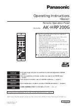
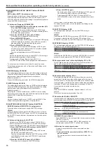
background image

Model No.

  AK-HRP200G

Operating Instructions

<Basics>

Remote Operation Panel

VQT4S52-5

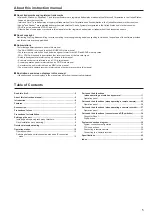
How●the●operating●instructions●are●organized

・●Basics●(this●manual):

This manual describes how to connect the unit to 

the required equipment and set it up.

Before installing the unit, be sure to read the 

<Basics> manual to ensure that you know how to 

install it correctly.

The <Basics> manual is provided as a PDF file on the 

CD-ROM supplied with the unit.

・●Operations●and●Settings:

Operations and Settings describe how to operate 

and set up the unit.

The <Operations and Settings> manual is provided 

as a PDF file on the CD-ROM supplied with the unit.

To●read●PDF●files,●you●will●need●Adobe

®

●Reader

®

.●

You●can●download●it●from●Adobe●Systems'●website.

SS1012KT5045 -PS

Printed in Japan

ENGLISH

Before operating this product, please read the instructions carefully and save this manual for future use.

DEUTSCH

Für Erlauterungen in Deutsch, konsultieren Sie bitte die mitgelieferte CD-ROM.  

(→ Seite 4)

FRANÇAIS

Pour des explications en français, veuillez vous reporter au CD-ROM fourni.  

(→ page 4)

ITALIANO

Per le istruzioni in italiano, vedere il CD-ROM in dotazione. (→ pagina 4)

ESPAÑOL

Para la explicación en español, consulte el CD-ROM suministrado. (→ página 4)

日本語

日本語版の取扱説明書は付属のCD-ROMに納められています。(→4ページ)

This manual is also contained as a PDF file on the CD-ROM supplied with the unit. (→page 4)

Summary of Contents for AK-HRP200G

Page 1: ...vided as a PDF file on the CD ROM supplied with the unit To read PDF files you will need Adobe Reader You can download it from Adobe Systems website SS1012KT5045 PS Printed in Japan ENGLISH Before operating this product please read the instructions carefully and save this manual for future use DEUTSCH Für Erlauterungen in Deutsch konsultieren Sie bitte die mitgelieferte CD ROM Seite 4 FRANÇAIS Pou...

Page 2: ... equipment has been tested and found to comply with the limits for a class A digital device pursuant to Part 15 of the FCC Rules These limits are designed to provide reasonable protection against harmful interference when the equipment is operated in a commercial environment This equipment generates uses and can radiate radio frequency energy and if not installed and used in accordance with the in...

Page 3: ...s IMPORTANT SAFETY INSTRUCTIONS 1 Read these instructions 2 Keep these instructions 3 Heed all warnings 4 Follow all instructions 5 Do not use this apparatus near water 6 Clean only with dry cloth 7 Do not block any ventilation openings Install in accordance with the manufacturer s instructions 8 Do not install near any heat sources such as radiators heat registers stoves or other apparatus includ...

Page 4: ...r sur le nom du document correspondant au manuel à consulter Adobe Reader est nécessaire pour lire les fichiers PDF Ce logiciel peut être téléchargé depuis la page d accueil d Adobe Systems ITALIANO Come aprire i file dei manuali di istruzioni per l uso Se inserendo il CD ROM si apre la schermata di installazione del software interrompere l installazione Aprendo INDEX pdf sul CD ROM viene visualiz...

Page 5: ...pes A studio handy camera is referred to as a camera in this manual A camera control unit is referred to as a CCU in this manual A remote operation panel is referred to as an ROP in this manual A master setup unit is referred to as an MSU in this manual The memory card camera recorder is referred to as the camera recorder in this manual Illustrations and screen displays in this manual Illustration...

Page 6: ... this unit 2 Unauthorized use of this unit by a third person with malicious intent 3 Interference or stoppage of this unit by a third person with malicious intent It is your responsibility to take sufficient network security measures such as those described below to protect yourself against the above risks Use this unit in a network secured by a firewall etc If this unit is used in a system with a...

Page 7: ...ou have unpacked the product CD ROM 1 Operating Instructions Basics Operating Instructions Operations and Settings Easy IP Setup Software ROP Setup Software Precautions for use Observe the following in addition to the information included in Read this first Handle carefully Do not drop the unit or expose it to strong impacts or vibrations Do not carry the unit by the iris lever The unit could be d...

Page 8: ...amaged Do not install the unit in a location where the temperature drops to 0 C 32 F or lower or reaches 40 C 104 F or higher Do not install the unit in a location exposed to direct sunlight or near exhaust vents that expel hot air Do not install the unit in a location exposed to excessive humidity dust or vibrations to prevent malfunction Setting up the unit Installing and removing rack mount bra...

Page 9: ...FLARE PED CAMERA No DTL DATA SET DISPLAY SELECT UP DOWN SET UP ND CC M GAIN M PED SHUTTER ND VR LOCK M GAIN IRIS M PED 10 19 CC SHT SYNC SELECT IRIS M PED LOCK IRIS M PED CHARA MENU SELECT TALLY CALL ALM OPT SENSE PUSH PREVIEW EXT D EXT COARSE AUTO FULL OPEN CLOSE CLOSE EXECUTE EXIT SAVE LOAD SHIFT UP DOWN 308 12 1 8 264 10 3 8 70 2 3 4 22 7 8 55 2 3 16 53 2 1 16 20 3 13 16 46 1 13 16 92 3 5 8 120...

Page 10: ...mote camera connected with a serial connection and CCUs and remote cameras connected with IP connections Connection not possible 1 device only Connection not possible Total of up to 18 devices Configuration with camera recorder connected with a combination of a serial connection and IP connection Connection not possible Connection not possible 1 device only Total of up to 18 devices Switching betw...

Page 11: ...r to the operating instructions supplied with the camera When the video signal is a camera signal or a color bar signal press and hold the Color Bar Signal Output BARS TEST button to select the TEST signal To switch from TEST signal output press the Color Bar Signal Output button BARS TEST to select camera video output On yellow CCU color bar and camera color bar On On green TEST signal On Off Cam...

Page 12: ... the message on the picture monitor PM on the CCU 7 5600 K button 5600K Use this function to change the amplification rate of the RB signals by an electrical circuit to achieve a white balance that corresponds to a 5600K color temperature When the 5600K button 5600K is set to On the B video signal is attenuated by about 6 dB the R video signal is boosted by about 3 dB while the G video signal is n...

Page 13: ...opened or after it has opened will persist when the power is turned off When scene file 5 is selected while AK HC3500A is connected the Scene File 1 SCENE1 USER1 button on the unit flashes Likewise for scene files 6 to 8 each of the Scene File 2 to 4 SCENE2 USER2 to SCENE4 buttons flashes Scene files 5 to 8 cannot be opened from the unit z z Opening a user file Hold down SHIFT while pressing the S...

Page 14: ...en the control is set to the paint control value stored in step 2 17 R gain control GAIN R Use this control to adjust the red R components of the white balance It is controlled by control lock VR LOCK 18 B gain control GAIN B Use this control to adjust the blue B components of the white balance It is controlled by the control lock VR LOCK 19 R flare pedestal control FLARE PED R Use this control to...

Page 15: ...IRIS value is displayed when the power is turned on Also when the Iris lever is operated while something other than IRIS is displayed on the setting display the IRIS value will be displayed for about 2 seconds 26 ND filter CC filter DISPLAY SELECT button ND CC SAVE LOAD button SAVE LOAD In setup mode Press this button to display and change set values for the ND or CC filters On yellow Displays the...

Page 16: ...en IRIS display or another ND CC M GAIN M PED display is selected The button lights and the SHUTTER display SHT where STEP SYNC is selected lights green Then the setting display shows the SHUTTER setting of STEP or SYNCHRO selected using the STEP SYNC select button STEP SYNC 2 Press the lit DATA SET button UP DOWN This allows you to change the SHUTTER setting 3 Press SHUTTER again The button goes ...

Page 17: ... the control privileges enabled The camera select button SELECT of the ROP with the control privileges enabled will be on The camera select buttons SELECT of the other ROPs will be flashing and operation for cameras will not be possible because the control privileges are disabled If you press the camera select button SELECT while it is flashing the control privileges will be enabled and operation ...

Page 18: ...r call lamp on AK HC3800 flashes 41 Alarm display ALM This indicator displays alarms Consult your supplier if a failure occurs On Lights when the camera fan stops due to a failure Alarm data can be displayed on the CCU PM When an alarm occurs the Character Menu button CHARA MENU on the unit lights and an alarm display appears like an interrupt on the CCU PM Flashing Indicates that the power voltag...

Page 19: ...direction Moving it to the rear adjusts it in the OPEN direction On The auto iris mode is enabled Off Manual manual adjustment using the iris lever is possible For details on auto iris settings refer to ROP menu setting in Operations and Settings on the supplied CD ROM 49 Iris close button CLOSE Use this button to forcibly set the iris to CLOSE On Forcibly sets the iris to CLOSE Off Cancels iris C...

Page 20: ...nce adjustment has started Flashing Warns that the automatic black balance adjustment ended without being completed Off Indicates that the black balance has been adjusted correctly Note This cannot be used with the AW HE2 6 Auto Setup button SETUP This cannot be used for a remote camera 7 5600 K button 5600K Use this button to make adjustments to achieve a white balance that corresponds to a 5600K...

Page 21: ...ing are GAIN R B PED FLARE R B and DTL Each press of the button turns the function on or off On ON locks the paint control value Off OFF the paint control value changes z z Using the control lock button VR LOCK 1 Use any of the controls 17 to 21 to adjust an item 2 Press VR LOCK The button lights The unit stores the paint control value at that point in time 3 Turn the control to its center positio...

Page 22: ...s on the supplied CD ROM 24 Setting display 4 digits This display indicates settings The IRIS value is displayed when the power is turned on Pressing one of the display select buttons displays the selected setting The range of settings are displayed Item Display AW HE50 AW HE60 AW HE120 AW HE870 IRIS A setting is not displayed ND _ _ _ 1 to 4 7 CC M GAIN dB 1 2 3 M PED 10 to 10 150 to 150 150 to 1...

Page 23: ...In setup mode use this to switch submenus For details on setup mode refer to Operations and Settings on the supplied CD ROM 27 ND filter display ND This display is lit green when an ND filter setting is displayed on the setting display Note ND filter cannot be used with AW HE50 AW HE60 AW HE870 AW HE2 28 CC filter display CC This cannot be used for a remote camera 29 M GAIN M PED DISPLAY SELECT bu...

Page 24: ...tings When SYNCHRO is selected the SYNCHRO display SYNC lights green This cannot be used with the AW HE2 34 SYNCHRO display SYNC This display is lit green when a SHUTTER SYNC setting is displayed on the setting display When STEP indication this display is off Off SHUTTER is in STEP mode On SHUTTER is in SYNCHRO mode Note Press and hold the STEP SYNC select button for about 2 seconds to switch betw...

Page 25: ... operation was disabled locked When the Iris lever is returned to the lock position the button turns off and normal control becomes possible This also flashes if the camera adjustment values and iris lever position are offset when the control target camera is switched At the point in time when the iris lever is moved to the position that matches the camera adjustment values the button turns off an...

Page 26: ...ENSE Use this control to adjust the ZOOM FOCUS speed Turn clockwise Increases the speed Turn counterclockwise Decreases the speed 51 Coarse control COARSE This is disabled for a remote camera 52 Lens extender indicator EXT This is disabled for a remote camera 53 Digital extender indicator D EXT This is disabled for a remote camera 54 Memory card slot Insert a memory card into this slot You can sav...

Page 27: ... that the auto black balance adjustment has started Flashing Warns that the automatic black balance adjustment ended without being completed Off Indicates that the black balance has been adjusted correctly 6 Auto Setup button SETUP This cannot be used with a camera recorder 7 5600 K button 5600K This cannot be used with a camera recorder 8 Matrix button MATRIX Use this function to correct saturati...

Page 28: ...on pressed lights and the user file is recalled after about 1 second and then the button goes off after about 1 second 15 Scene user file store button STORE This cannot be used with a camera recorder Note When operating the camera recorder the only operation possible is to recall one of scene files 1 to 3 Register files on the camera recorder without connecting the ROP GAIN FLARE PED DTL VR LOCK 1...

Page 29: ...n UP DATA SET button DOWN and Scene User File selector button SHIFT for about 2 seconds switches to setup mode ND filter CC filter ZOOM FOCUS AUTO FOCUS and VFR are not supported by all models For details on setup mode refer to Operations and Settings on the supplied CD ROM 24 Setting display 4 digits This display indicates settings The IRIS value is displayed when the power is turned on Pressing ...

Page 30: ... VFR OFF The lit DATA SET button UP DOWN allows you to select 7 Press ND CC again The setting display switches to the IRIS display status In setup mode use this to switch submenus For details on setup mode refer to Operations and Settings on the supplied CD ROM 27 ND filter display ND Lights when the ND filter position is displayed on the adjustment value display Lit green Standard position Lit ye...

Page 31: ...R SYNC setting is displayed on the setting display When STEP indication this display is off Off SHUTTER is in STEP mode On SHUTTER is in SYNCHRO mode Note During shutter on operation the adjustment value can be switched back and forth between STEP and SYNCHRO by pressing the STEP SYNC select button for about 2 seconds Whether shutter speed settings in SYNCHRO mode are displayed in seconds sec or a...

Page 32: ...led locked Flashes red Quick flashing rate of once every second Indicates that the Iris lever was operated when operation was disabled locked When the Iris lever is returned to the lock position the button turns off and normal control becomes possible This also flashes if the camera adjustment values and iris lever position are offset when the control target camera is switched At the point in time...

Page 33: ...indicator EXT This indicator lights to warn that the lens extender is set to something other than 1x On The lens extender is set to something other than 1x Off This indicates that the lens extender is not being used or that it is not available 53 Digital extender indicator D EXT This indicator lights to warn that the digital extender is set to something other than 1x On The digital extender is set...

Page 34: ...en directly connecting a device to the unit connect it with a crossover cable category 5 or better shielded cable When connecting via a hub switching hub 100base TX or other device connect it with a straight cable category 5 or better shielded cable 5 12 V DC connector 12 V IN Hirose Electric HA16RA 4P 77 A 12 V DC connector for connecting an AC adapter Pin number Function 1 GND 2 NC 3 NC 4 12V No...

Page 35: ...not connect Configuration with camera recorder connected with a serial connection Connection not possible Connection not possible 1 device only Do not connect IP connection mode Configuration with IP connections only Do not connect Do not connect Do not connect Total of up to 19 devices Required Configuration with a combination of a CCU connected with a serial connection and CCUs and remote camera...

Page 36: ...ower of the camera Note If a camera is not connected some of the control functions from the unit to the CCU will be limited Up to 19 CCUs AK HCU200 can be controlled from the unit To use a CCU via an IP connection you need to configure the settings with ROP Setup Software accessory Before using ROP Setup Software connect the unit to the personal computer with a LAN cable For details on the setting...

Page 37: ...e communication protocol of AK HC1500 to PROTCOL3 convertible PC control protocol Make sure you configure the setting on the cameras individually before installation Cable specifications 12V IN LAN RS 422 PREVIEW CCU SIGNAL GND AK HC1500 Cable to prepare up to 1 000 m AW PS550 option RJ 45 Modular Connector 8 pin Plug CAT 5 Male D Sub 15 pin Male Connector DHW10 153F200 Advanced Connector Inc Cove...

Page 38: ...mmunication protocol of AK HC1800 to PROTCOL3 convertible PC control protocol Make sure you configure the setting on the cameras individually before installation Cable specifications 12V IN LAN RS 422 PREVIEW CCU SIGNAL GND AK HC1800 Cable to prepare up to 1 000 m RJ 45 Modular Connector 8 pin Plug CAT 5 Male D Sub 15 pin Male Connector DHW10 153F200 Advanced Connector Inc Cover DE C8 J9 F5 1R Jap...

Page 39: ...interface cable AW CA20T6G is required for a serial connection with a remote camera AW HE50 AW HE60 Use a straight cable category 5 or better shielded cable for the LAN cable Serial connection AW HE120 12V IN LAN RS 422 PREVIEW CCU SIGNAL GND AK HRP200 Supplied AC adapter External DC power supply LAN cable straight cable up to 1 000 m AW HE120 1 Connect the RS 422 connector RS 422 of the unit and ...

Page 40: ...able for the LAN cable When not connecting via a switching hub use a cross cable category 5 or better shielded cable for the LAN cable 2 When you have finished connecting the equipment turn on the power of the camera and turn on the external DC power supply of the unit Note Up to 19 cameras AW HE50 AW HE60 AW HE120 can be controlled from the unit To use a remote camera via an IP connection you nee...

Page 41: ... category 5 or better shielded cable for the LAN cable 2 When you have finished connecting the equipment turn on the power of the camera and turn on the external DC power supply of the unit Note Up to 19 camera recorders and remote cameras can be controlled from this unit To use a remote camera via an IP connection you need to configure the settings with ROP Setup Software accessory Please make su...

Page 42: ... extender indicator 19 26 33 Dip Switch 34 DTL control 14 21 28 E EXECUTE button 16 24 31 EXIT button 16 23 30 F Fader full button 19 26 33 I IP connection mode 10 IP connector 34 Iris close button 19 26 33 IRIS display 15 22 29 Iris lever 19 25 32 Iris master pedestal lock button 18 25 32 K Knee OFF button 12 20 27 L Lens extender indicator 19 26 33 M Master pedestal control 19 25 32 Matrix butto...

Page 43: ...43 Memo ...

Page 44: ...h general household waste For proper treatment recovery and recycling of old products please take them to applicable collection points in accordance with your national legislation By disposing of them correctly you will help to save valuable resources and prevent any potential negative effects on human health and the environment For more information about collection and recycling please contact yo...

Reviews: