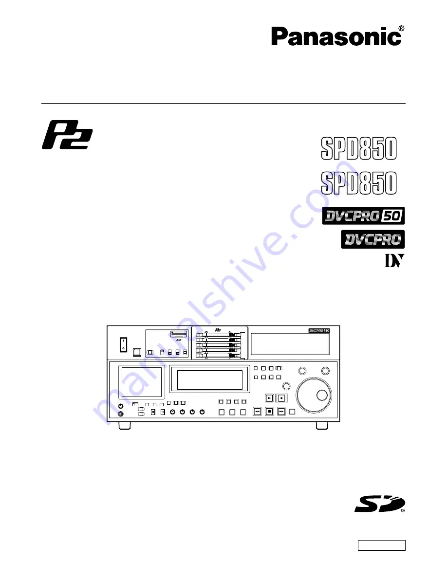
background image

Operating Instructions

Memory Card Recorder

AJ-

P

Model No. 

AJ-

E

Before operating this product, please read the instructions carefully and save this manual for future use.

ENGLISH

Summary of Contents for AJSPD850P - P2 DECK

Page 1: ...Operating Instructions Memory Card Recorder AJ P Model No AJ E Before operating this product please read the instructions carefully and save this manual for future use ENGLISH...

Page 2: ...hich is effectively grounded through normal household wiring Extension cords used with the equipment must be threecore and be correctly wired to provide connection to the ground Incorrectly wired exte...

Page 3: ...oltage in the range of 100 240 V AC Voltage other than 120 V is not intended for U S A and Canada CAUTION Operation at a voltage other than 120 V AC may require the use of a different AC plug Please c...

Page 4: ...aced If you lose the fuse cover the plug must not be used until a replacement cover is obtained A replacement fuse cover can be purchased from your local Panasonic Dealer FOR YOUR SAFETY PLEASE READ T...

Page 5: ...ventilation Ensure that curtains and any other materials do not obstruct the ventilation to prevent risk of electric shock or fire hazard due to overheating CAUTION Even when the Power Switch is in th...

Page 6: ...Included with this product is software licensed under the GNU General Public License GPL and GNU Lesser General Public License LGPL and users are hereby informed that they have the right to obtain ch...

Page 7: ...AJ P2C002SG which is sold separately that conform to the PC card type II standard It can record and play video and audio in the DVCPRO50 DVCPRO and DV compression formats It has a 3 5 inch color LCD...

Page 8: ...MXF file SMPTE390M and clip meta data in XML 5 PC card slots The unit comes with five PC card slots into which you can insert PC card type II cards You can record and play audio and video material on...

Page 9: ...puter with USB2 0 you can use the P2 cards in the memory card recorder as mass storage At this time front panel controls of the memory card recorder are disabled You will need to install the USB drive...

Page 10: ...s 1 FF NEXT button Press to fast forward Select the speed at setup menu No 102 FF REW MAX By pressing the FF button in the stop mode while pressing the SHIFT button you can find the beginning of the n...

Page 11: ...In the thumbnail screen press to switch on or off the marker in the clip indicated by the cursor SET button Press to confirm settings in the thumbnail screen in the setup menus and when creating play...

Page 12: ...You cannot select SDI and 1394 unless you have installed the optional board AJ YA755G AJ YAD850G Settings AUDIO button USER SET Setup menus No 715 CH1 IN SEL ANA No 716 CH2 IN SEL DIGI No 717 CH3 IN S...

Page 13: ...th the dial CHROMA LEVEL dial and switch When ENC CONTROL is set to LOCAL you can adjust the chroma level When set to PRESET the chroma level is a unity value 0 dB When set to MANUAL you can adjust th...

Page 14: ...rotected In this status recording is not possible AUDIO VIDEO 625 525 Operation mode displays The card transport status is displayed here Normal playback or recording Playback at a speed slower than 1...

Page 15: ...ON Remote control connectors Connect the memory card recorder to an external controller ENCODER REMOTE connector Connect the memory card recorder to an external encoder to adjust video output signal...

Page 16: ...onent to control the memory card recorder ANALOG AUDIO OUT connectors Output analog audio signals MONITOR OUT connectors During playback a mixed signal is output from the CH1 CH2 CH3 CH4 audio signals...

Page 17: ...t has been inserted while its corresponding access LED is flashing orange 1 Press the STOP button If the access LED corresponding to the P2 card you want to remove is flashing orange press the STOP bu...

Page 18: ...cess LED Recording and play are possible Green lighting The memory card recorder is accessing to record or play Orange flashing Recording and play are possible The card is selected for recording Orang...

Page 19: ...E ONLY AC IN SIGNAL GND AES EBU CH1 2 IN CH3 4 IN CH1 2 OUT CH3 4 OUT SDI IN OUT 1 2 3 SUPER ACTIVE THROUGH IN OUT OPUTION 1 2 ANALOG ANALOG REMOTO Y VIDEO IN PB PR Y PB PR ON OFF 75 REF VIDEO IN ON O...

Page 20: ...eave it at the center position 2 Press the SHTL SLOW button and switch to SHTL or SLOW 3 Turn the search dial When the SHTL lamp lights the playback picture speed changes from 0 up to 32x depending on...

Page 21: ...leting voice memos Formatting P2 cards Displaying clip properties and P2 card status Overview of thumbnail operations The thumbnail screen is organized as shown below Working with clip thumbnails THUM...

Page 22: ...dial TC REGEN PRESET switch Display status The display status indicates the type of thumbnails displayed on the screen ALL All clips are displayed SELECTED Clips selected by the user are displayed MA...

Page 23: ...p indicators were displayed For details see Repairing clips on page 26 Clips which contain red bad clip indicators cannot be repaired so they should be deleted If a clip cannot be deleted format the P...

Page 24: ...COUNTER MENU TC PRESET SELECT SLOT RESET THUMBNAIL MARKER BAR MENU SET SEARCH REC PLAY FF REW STOP PREV NEXT SHIFT SHTL PUSH JOG SLOW Memory Card Recorder AJ TC GEN SET REC RUN FREE RUN DIAG MENU BAR...

Page 25: ...ayed here The pointer moves 4 Move the pointer to the clip containing the voice memo you want to play and then press the SET button The pointer moves to the lower part of the LCD screen 5 Use the sear...

Page 26: ...if a clip is bad it has a bad clip mark on it 3 Press the SET button to select the clip 4 Press the MENU BAR button On the menu bar select OPERATION then REPAIR CLIP A YES NO dialog box is displayed...

Page 27: ...s year month day YMD This setting applies to the recording date displayed under clip properties and the recording date and time displayed when DATE is selected for DATA DISPLAY THUMBNAIL SIZE Either L...

Page 28: ...rd status The remaining recording capacity of the P2 card is indicated here by a meter and in terms of a percentage One of the following messages may be displayed instead depending on the card status...

Page 29: ...screen shows video output and the IN OUT point TC and event number are shown in captions INSERT button This button is used to add a new event while the play list summary is displayed Move the pointer...

Page 30: ...r is as follows Play list screen with no events registered yet Play list screen with events already registered Event screen Register or change the IN and OUT points while viewing the images Set the SU...

Page 31: ...multiple clips example PLAYLIST button EVENT button IN button ENTRY button OUT button ENTRY button EVENT button Flow of operations in creating a play list registering an event Also when registering a...

Page 32: ...f the event to be changed and press the EVENT button to switch to the event screen Play the images and press the IN or OUT ENTRY buttons to change the IN or OUT point Notes If the changed IN point com...

Page 33: ...hat if the number of events exceeds 100 the play list data for the events exceeding 100 will not be imported Playing the play lists You can start playing a play list from the event where the pointer i...

Page 34: ...enu screen cursor moves and the item number on the display flashes When the dial is turned clockwise the item number is incremented from 001 002 003 004 and so on conversely when it is turned counterc...

Page 35: ...the search dial while holding down the SEARCH button to select whether the lock mode is to be set or released To set the lock mode Set 0001 ON as the setting To release the lock mode Set 0000 OFF as...

Page 36: ...ttings are stored in the memory If the USER1 settings are not to be stored in the memory do not press the SET button but press the MENU button instead Saving user files 1 Press the MENU button 2 Press...

Page 37: ...spect to the video output 0000 100 0100 0 0200 100 The underlined items indicates the initial setting 18 SYS H OFFSET System phase adjustment 0000 3 13 4 sec 0001 2 8 96 sec 0002 1 4 52 sec 0003 0 0 s...

Page 38: ...ining time is displayed on the first line and the total time is displayed in the second line Notes When 2L is selected the remaining time is not displayed if TIME has been selected as the setup menu i...

Page 39: ...rs if a warning or error has occurred when T S M has been selected as this setting The recording duration and recording time and date are displayed when the DV format applies The operating status is d...

Page 40: ...GE has been selected only time data is displayed regardless of the setup menu No 008 DISPLAY SEL setting 01 MONTH 02 DAY Sets the month Note If a nonexistent day is set while setting Feb April June Se...

Page 41: ...y region difference difference 00 00 Greenwich 13 00 00 30 10 30 Lord Howe Island 01 00 Azores 12 00 New Zealand 01 30 09 30 Darwin Islands 02 00 Central Atlantic time 11 00 Solomon Islands 02 30 08 3...

Page 42: ...AUTO EE SEL This selects the memory card recorder mode in which the EE status is established when the MODE switch is set to EE 0000 S F R EE status is established in STOP FF and REW modes However EE...

Page 43: ...INH This selects whether video input switching using the INPUT SELECT button is to be enabled or disabled 0000 OFF Video input switching using the INPUT SELECT button is enabled 0001 ON Video input s...

Page 44: ...232C data length Unit bit 0000 7 0001 8 202 ID SEL This sets the ID information to be returned to the controller 0000 OTHER 0001 DVCPRO 0002 ORIG Notes ID information of any VTR except for the DVCPRO...

Page 45: ...r with the STD input signal at the AUTO1 setting The AUTO1 setting is selected when the STD signal is to be used Note At the AUTO setting the images shown on the front panel s LCD monitor will be sign...

Page 46: ...EL This selects the time code to be used when an external time code is to be used 0000 LTC The LTC of the TIME CODE IN connector is used 0001 VITC The VITC of the input video signal is used No Item De...

Page 47: ...e input compressed signals will be recorded regardless of this menu s setting The underlined items indicates the initial setting No Item Description 600 INT SG This selects the internal signal 0001 BB...

Page 48: ...ed as the input signals the input information will be recorded Setup menus continued USER menu VIDEO No Item Description 609 EDH This selects whether to superimpose EDH onto the SDI output signals 000...

Page 49: ...al is output in its original form 0001 CUT The signal is output with the 7 5 setup removed 0002 ADD The signal is output with the 7 5 setup added No Item Description 623 SETUP 50 For AJ SPD850P Sub sc...

Page 50: ...s the line on which the UMID information is to be superimposed Note The line selected for the setup menu item No 501 VITC POS 1 and No 502 VITC POS 2 settings cannot be selected for this item 625i sys...

Page 51: ...has been selected by pressing the memory card recorder s AUDIO INPUT SELECT button 0000 ANA Analog input 0001 DIGI Digital input 716 CH2 IN SEL This selects the CH2 input when USER SET has been selec...

Page 52: ...C422 The 422 mode signals are recorded on 1 line 0002 YC411 The 411 mode signals are recorded on 1 line 0003 Y1_B W Only the Y signal is recorded on 1 line directly 0004 Y1_BPF Only the Y signal is re...

Page 53: ...ed on 2 lines 0002 Y4_B W Only the Y signal is recorded on 4 lines directly 0003 Y4_BPF Only the Y signal is recorded on 4 lines after it has been separated from the C signal 0004 C4 Only the C signal...

Page 54: ...s menu option is not displayed in the 625i system VITC signals are often mistakenly detected as teletext signals when the NABTS system has been selected If this happens select MANU as the setting for...

Page 55: ...xt signals can be recorded depends on the number of recording lines which was entered as the setup menu No 800 ADD LINE 25 or No 801 ADD LINE 50 setting See Number of lines which can be set for TELETE...

Page 56: ...saved No Item Description A02 P ON LOAD This loads the contents of the selected user file into USER1 and it starts operation with the USER1 settings when the power is turned on 0000 OFF Operation is...

Page 57: ...To change the value turn the search dial while holding down the SEARCH button Turn the search dial to select the set of digits that is to be set The digits selected start flashing The setting ranges...

Page 58: ...R appears when the data could not be read properly from the card Characters displayed The background of characters superimposed on the display can be changed using setup menu No 011 CHARA TYPE TCR TCR...

Page 59: ...No 600 INT SG setting When the REF VIDEO input signal is available Synchronization with the REF VIDEO input signal When the REF VIDEO input signal is not available Internal synchronization Start What...

Page 60: ...ing selection setup menu No 727 PB FADE is CUT Audio signal A Audio signal B Noise appears at the edit splice Audio signal A Audio signal B V fade is performed instantaneously to eliminate the noise W...

Page 61: ...CH3 input CH4 input CH3 input CH4 input CH3 input CH4 input CH3 input CH4 input Monitor output L R Output signal CH1 CH2 CH3 CH4 CH1 CH2 CH3 CH4 CH1 CH3 CH2 CH4 CH1 CH2 CH3 CH4 CH1 CH2 CH3 CH4 CH1 CH3...

Page 62: ...total 6 screws The letters A to H are not actually marked on the side panels 2 Attach the outer member brackets to the rack Check that the height is the same for the left and right brackets 3 Remove...

Page 63: ...locations such as these leave it standing for about 10 minutes rather than switching on the power immediately Maintenance Before starting any maintenance work switch the power to OFF and holding the...

Page 64: ...Displaying the DIAG menu 1 Press the DIAG button The DIAG menu screen is displayed on the monitor and the message is displayed on the counter display 2 Press the SEARCH button Each time the button is...

Page 65: ...ed An attempt has been made to record data when the card has no more free memory space on it An attempt has been made to record on a card that cannot be used The card status has changed during recordi...

Page 66: ...99H POWER ON The number of times the power has been turned on is displayed in single units H30 0T 99999T Notes The resettable items in the HOURS METER information are reset by the shop when performing...

Page 67: ...XD CTS RTS DTR SG DSR deck side PC side D SUB 9 pin connector Software specifications Protocol Communication parameters Communication system Communication speed Bit length Stop bit Parity bit ACK code...

Page 68: ...d command received Error in command execution ER002 Parameter error ER1FF Deck system error STX ERN1 N2 N3 ETX 02h Error code 03h ACK 06h NACK 15h STX command data ETX 02h XX XX XX XX XX 03h ACK 06h D...

Page 69: ...CTL mode g SP 20h for a plus display 2Dh for a minus display h 0 9 hours TC mode gh 00 23 hours mm 00 59 minutes ss 00 59 seconds 525i system ff 00 29 frames 625i system ff 00 24 frames Note CTL or TC...

Page 70: ...from PC Clear to send Shorted with pin 5 Request to send Shorted with pin 4 Data terminal ready No processing Signal ground Signal ground Data set ready voltage output after communication enable stat...

Page 71: ...0 dB S N ratio Better than 55 dB K factor Less than 1 Y 2T Y C delay Less than 20 nsec Composite IN composite OUT Video bandwidth For AJ SPD850P Y 30 Hz to 5 5 MHz 3 0 dB For AJ SPD850E Y 25 Hz to 5 5...

Page 72: ...AES EBU format SDI input option BNC x 2 active through complies with SMPTE259M C 272M A ITU R BT 656 4 standard Audio Output Connector Analog output CH1 CH2 CH3 CH4 XLR x 4 low impedance 4 0 20 dBu s...

Page 73: ...gion 1707 N Randall Road E1 C 1 Elgin IL 60123 847 468 5200 WESTERN ZONE 3330 Cahuenga Blvd W Los Angeles CA 90068 323 436 3500 Government Marketing Department 52 West Gude Drive Rockville MD 20850 30...

Reviews: