


Operating Instructions
Memory Card Camera-Recorder
Before operating this product, please read the instructions carefully and save this manual for future use.
ENGLISH
VQT5J85A(E)
W0214HM0 -YI
Model No.
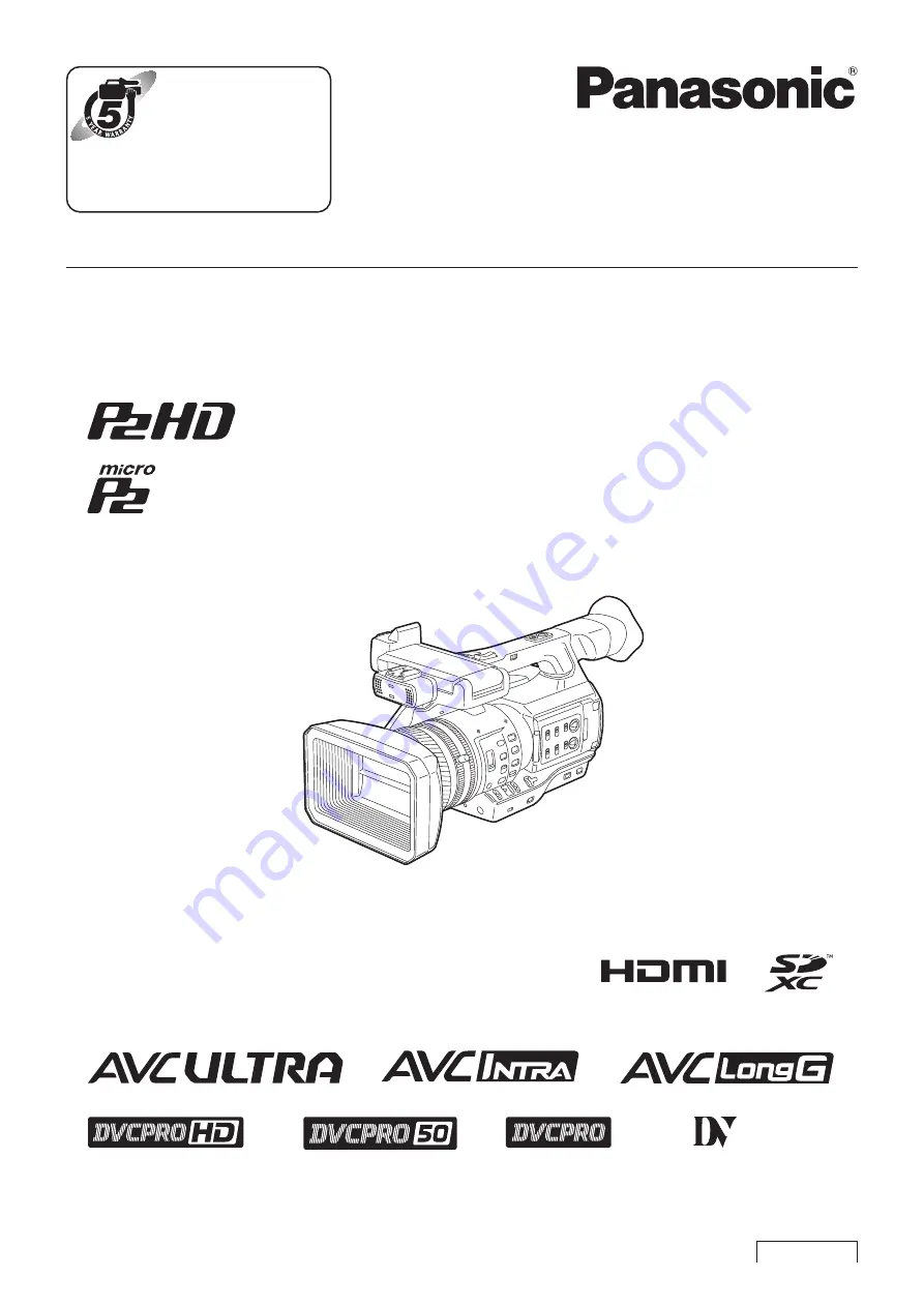
AJ-PX270EJ
Register now!!
This product is eligible for
the P2HD 5 Year Warranty
Repair Program.
For details, see page 5.
http://panasonic.biz/sav/pass_e/


