background image

TROUBLE- SHOOTING

PLA

Y

BACK

P

R

EP

ARA

TION

DESCRI

PTION 

OF P

ARTS

BEFORE USE

SPECIFI- CA

TIONS,

OTHER

SHOOTING

EDITING

DISPLA

Y

S

MENU

S

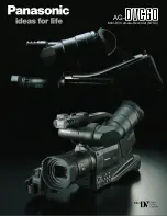
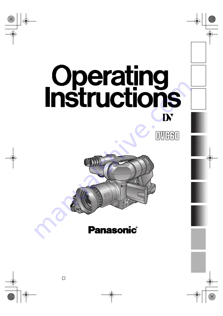
Digital Video Camera-Recorder

Model AG-

E

F0804S0 -H

VQT0N17

D

Mini

PAL

Before operating this product, please read the instructions carefully and save this manual for 
future use.

Printed in Japan

AG-DVC60E_En.fm  1 ページ  2004年9月2日 木曜日 午後1時43分

Summary of Contents for AGDVC60 - DIGITAL VIDEO CAMCORDER

Page 1: ...ATIONS OTHER SHOOTING EDITING DISPLAYS MENUS Digital Video Camera Recorder Model AG E F0804S0 H VQT0N17 D Mini PAL Before operating this product please read the instructions carefully and save this manual for future use Printed in Japan AG DVC60E_En fm 1 ページ 2004年9月2日 木曜日 午後1時43分 ...

Page 2: ...K FOR U K ONLY FOR U K ONLY This appliance is supplied with a moulded three pin mains plug for your safety and convenience A 5 amp fuse is fitted in this plug Should the fuse need to be replaced please ensure that the replacement fuse has a rat ing of 5 amps and that it is approved by ASTA or BSI to BS1362 Check for the ASTA mark or the BSI mark on the body of the fuse If the plug contains a remov...

Page 3: ...TORE ONLY IN LOCATIONS WHICH ARE NOT EXPOSED TO THE RISK OF DRIPPING OR SPLASHING LIQ UIDS AND DO NOT PLACE ANY LIQUID CONTAINERS ON TOP OF THE EQUIP MENT CAUTION TO REDUCE THE RISK OF FIRE OR SHOCK HAZARD AND ANNOYING INTERFERENCE USE THE RECOM MENDED ACCESSORIES ONLY CAUTION Do not install or place this unit in a bookcase built in cabinet or any other confined space in order to maintain ade quat...

Page 4: ...primaire voeding en het reservege heugen van het apparaat alsmede voor de afstandsbediening wordt gebruik gemaakt van een batterij Wanneer de batterij uitgeput is mag u deze niet gewoon weggooien maar dient u ze als klein chemisch afval weg te doen To remove the battery Verwijderen van de bat terij Main Power Battery Batterij Voor Primaire Voeding Battery eject button Batterij verwijderknop AG DVC...

Page 5: ...a recorder menu screens etc in these operating instructions will differ slightly from the actual camera recorder If the operations described can be performed using either the camera recorder or the remote control unit an illus tration of the remote control unit is shown alongside Reference pages Reference pages are indicated as P00 Usable cassette tapes Digital video cassette tapes with the mark c...

Page 6: ...n 36 Index recording 36 Still shooting 36 Color bars 36 Backup recording 37 Switching to manual mode 37 Focusing 37 Shutter speed iris and gain adjustments 38 Shutter speed adjustment 38 Iris and gain adjustments 39 White balance adjustments 40 Auto white balance 40 Setting the white balance 40 Adjusting the white balance manually 41 Audio input select and level adjustments 42 Selecting audio inpu...

Page 7: ...50 External microphone 51 Audio dubbing 52 Dubbing 54 Analog input 54 Analog output 55 Digital input output 56 Screen displays 57 Displays in CAMERA and VCR modes 57 In VCR mode only 60 Warnings 60 Using the MODE CHK button 61 Setting the DISPLAY items 61 Menu operations 62 Setting the menu mode 62 Selecting the main items 62 Selecting the sub items 63 Entering the settings 63 Setting other sub it...

Page 8: ...n inserting or removing the cassettes AC adapter and battery If the battery has become extremely hot or cold or if it has not been used for a long time and has no charge the CHARGE lamp will blink several times and charg ing will start automatically If the CHARGE lamp continues to blink even when the battery temperature is normal it may mean that something is wrong with the battery or AC adapter C...

Page 9: ...mage or characters are left displayed on the LCD monitor or viewfinder for an extended period they may become burned onto the screen However if the power is kept off for several hours the screen will return to normal The liquid crystal parts are manufactured using high precision technology More than 99 99 of the pixels are effective which means that less than 0 01 of the pixels are missing or perm...

Page 10: ...nsert the cassette tape Getting ready Connecting the power cord Connect the cords properly as shown in the fig ure above The battery cannot be charged when power is being supplied to the camera recorder from the AC adapter AC adapter AC cord DC cord Mini DV cassette tape N O O P The AC adapter is designed to switch over automati cally to the supply voltage 110 V 120 V 220 V or 240 V and frequency ...

Page 11: ...y retracted before closing the cassette cover Turn the POWER lever to the ON position The CAM red lamp lights and the camera recorder switches to shooting pause mode 1 Set the AUTO MANUAL selector switch to AUTO 2 Squeeze both sides of the lens cap and remove it 3 Look through the viewfinder and check what you want to shoot 4 Shooting starts when you press the START STOP red button on the POWER le...

Page 12: ...ompletely retracted Checking what you have shot rec check You can conduct an image search P31 by holding down the t button in the shooting pause mode Do not hold down the t button when conducting a rec check Tape protection mode If you leave the camera recorder in the shooting pause mode for 5 minutes or so the camera recorder will automatically switch to the tape protection mode and its power wil...

Page 13: ...te cover if you are not going to insert a cassette tape immediately after removing another Do not attempt to remove a tape while you are recording The cassette cover opens but recording will continue allowing outside light and dust to adversely affect the tape Turning off the power Disconnecting the power cord Turn the POWER lever to the OFF position check that the POWER lamp CAM VCR has gone off ...

Page 14: ... cover and adjust the strap length 2 Close the cover firmly Attaching the shoulder strap We recommended that you attach the shoulder strap to help you avoid dropping the camera recorder 13 16 inch 20 mm or more 13 16 inch 20 mm or more AG DVC60E_En fm 14 ページ 2004年9月2日 木曜日 午後1時43分 ...

Page 15: ...ay apply to some of the memory func tions and or regular playback may not be possible when a tape shot in the LP mode using this camera recorder is played back in another digital video unit a tape shot in the LP mode using another digital video unit is played back in this camera recorder a tape shot in the LP mode using this camera recorder is played back in another digital video unit that does no...

Page 16: ...ilt in stereo microphone START STOP button P31 OPEN EJECT lever P10 12 USER 1 button P36 46 52 POWER lamp P11 POWER lever P11 13 Hand strap P14 Cassette holder P10 12 Cassette cover P10 12 Tripod mounting hole P9 White balance sensor P40 S VIDEO IN OUT connector P50 XLR AUDIO IN connector P51 Tally lamp P77 Focusing ring P31 37 Lens hood P15 32 Lens Infrared light P32 Tally lamp P77 VIDEO IN OUT c...

Page 17: ...USER2 button P36 46 52 FOCUS button P37 WHITE BAL button P40 41 Multi dial P23 25 29 38 39 42 44 46 62 MENU button P23 25 27 29 42 62 64 D ZOOM q button P31 43 45 SEARCH y button P31 43 45 USER 3 g button P36 43 55 56 STILL h button P43 45 OIS Optical Image Stabi lizer button P33 ZEBRA button P34 AUTO MANUAL selector switch P11 30 37 38 40 41 Panel locking button P12 Eye cup Viewfinder P11 22 Diop...

Page 18: ...button 2 P33 15 START STOP button 2 P30 16 ZOOM VOL buttons 2 P31 44 2 During shooting these buttons function in exactly the same way as the corresponding buttons on the camera recorder 17 VAR SEARCH button P46 18 MENU button P23 25 27 42 62 64 19 buttons P23 25 29 42 44 46 47 62 63 Wireless remote control unit Note that the following buttons are for functions that cannot be executed on the camera...

Page 19: ...his is located at the lower side of the lens on the camera recorder Point the wireless remote control unit towards the sensor when operating the camera recorder with it Setting procedure Wireless remote control unit Press the STOP g and STILL ADV buttons at the same time to set the remote control unit for use with VCR1 Alternatively press the STOP g and STILL ADV buttons at the same time to set th...

Page 20: ...tery Short circuiting may occur across the terminals causing the battery to heat up and you may seriously burn yourself if you touch the battery in this state The battery becomes hot while it is being used or charged Similarly the camera recorder body becomes hot during use If recording and stopping are done unnecessarily and repeatedly the recording time will be less than the figure given in the ...

Page 21: ... place To remove the battery hold down the battery release button and slide it up Mounting Removing Turn the POWER lever to the OFF position check that the POWER lamp CAM VCR has gone off and then remove the battery Support the battery with your hand so that it does not drop off AG DVC60E_En fm 21 ページ 2004年9月2日 木曜日 午後1時43分 ...

Page 22: ...r so that the char acters on the viewfinder screen are seen most clearly 1 Set the POWER lever to the ON position 2 Open the LCD monitor while holding down the panel locking button The LCD monitor can be opened to a maximum angle of 90 Forcing it past this point will damage the cam era recorder 3 Position the LCD monitor where it is easiest to see The monitor can be rotated by 180 degrees toward t...

Page 23: ... ibsbi i a _ofdeqkbpp mrpe jbkr ql obqrok x H z x H z x H z x z x z x z PB ZOOM MENU SET ITEM SHUTTER IRIS VOL JOG PUSH i aLbsc pbq bsc _ofdeqkbpp i a lilo ibsbi i a _ofdeqkbpp mrpe jbkr ql obqrok x H z x z x H z x z x H z x z PB ZOOM MENU SET ITEM SHUTTER IRIS VOL JOG PUSH i aLbsc pbq bsc _ofdeqkbpp i a lilo ibsbi i a _ofdeqkbpp mrpe jbkr ql obqrok x z x H z x z x H z x z x H z PB ZOOM MENU SET I...

Page 24: ...finder images P72 No matter whether color or black and white is selected the images will have the same resolution When you press the USER button to which the EVF DTL function has been allocated the contours of the images in the viewfinder and LCD monitor are emphasized making it easier to bring the subject into focus P68 Note that the contours of the images will still be emphasized to make focusin...

Page 25: ...bkr ql obqrok objlqb as ja pbi as lkqoli ob i jm _bbm plrka il h pbq s oN lcc lcc ob m lcc vbp PB ZOOM MENU SET ITEM SHUTTER IRIS VOL JOG PUSH il h pbq mrpe jbkr ql obqrok vb o a v jlkqe elro jfkK mo T OQ NP OMMQ PB ZOOM MENU SET ITEM SHUTTER IRIS VOL JOG PUSH il h pbq mrpe jbkr ql obqrok vb o a v jlkqe elro jfkK mo T OQ NP OMMQ PB ZOOM MENU SET ITEM SHUTTER IRIS VOL JOG PUSH JAN January FEB Febru...

Page 26: ...the RECORDING SETUP screen 3 Turn the multi dial to move to the UB PRESET item 4 Press the multi dial to move q to YES 5 The screen shown below appears Set the user s bit using the multi dial Turn the multi dial and select the user s bit charac ters Numbers from 0 to 9 and letters from A to F can be used as the characters that make up the user s bit Charging the internal battery Setting the user s...

Page 27: ...EGEN item setting If the RESET button counter is pressed when the user s bit has been set the user s bit is cleared to zero r_ mobpbq mrpe jbkr ql obqrok c M M M M M M M PB ZOOM MENU SET ITEM SHUTTER IRIS VOL JOG PUSH OSD COUNTER RESET TITLE VOL MULTI P IN P REC A DUB ZOOM DATE TIME PHOTO SHOT START STOP CH1 CH2 AUDIO LEVEL REC MODECHK SNS OIS ZEBRA RESET COUNTER ZOOMSPEED OFF M H L AUDIO IN FRONT...

Page 28: ...lcc lk ob loafkd pbqrm mrpe jbkr ql obqrok cfopq ob q r_ mobpbq q mobpbq lkb pelq ob ob qfjb obdbk MKR lcc mobpbq r_ jlab rpbo bccb q lcc PB ZOOM MENU SET ITEM SHUTTER IRIS VOL JOG PUSH ob loafkd pbqrm mrpe jbkr ql obqrok cfopq ob q r_ mobpbq q mobpbq lkb pelq ob ob qfjb MKR lcc mobpbq r_ jlab rpbo vbp bccb q lcc PB ZOOM MENU SET ITEM SHUTTER IRIS VOL JOG PUSH ob loafkd pbqrm mrpe jbkr ql obqrok c...

Page 29: ...bqrok N M Ü M M ã M M ë M M Ñ PB ZOOM MENU SET ITEM SHUTTER IRIS VOL JOG PUSH OSD COUNTER RESET TITLE VOL MULTI P IN P REC A DUB ZOOM DATE TIME PHOTO SHOT START STOP CH1 CH2 AUDIO LEVEL REC MODECHK SNS OIS ZEBRA RESET COUNTER ZOOMSPEED OFF M H L AUDIO IN FRONT REAR CH1 CH2 MIC MIC LINE RESET SELECT STORE OFF ON P B DIGITAL VAR SEARCH PB ZOOM MENU SET ITEM MENU q mobpbq mobpbq lh kl mrpe gld vbp PB...

Page 30: ...ed automatically and manually P39 g Time data P25 29 Check that the calendar and time have been set correctly Check that the time code and user s bit have been set correctly g Audio input P42 Check that the audio input switch is in the correct position 1 Set the AUTO MANUAL selector switch to the AUTO position 2 Squeeze both sides of the lens cap and remove it 3 Look through the viewfinder and che...

Page 31: ...W MODE screen the digital zoom function works at the following magnification levels each time this button is pressed 1 25 1 5 1 OFF Zooming at a maximum level of k24 is possible at this setting If on the other hand 160 is selected as the item s setting the digital zoom function works at the following magnification levels each time this button is pressed 2 5 10 1 OFF Zooming at a maximum level of 1...

Page 32: ...s the TIME STAMP item set ting appears on the screen The time stamp cannot be recorded when 160 has been selected as the D ZOOM item setting on the SW MODE screen P69 This camera recorder comes with a high sensitivity shooting function to enable shooting in very dark places You can shoot scenes in three high sensitivity shooting modes which you could not capture using a regular camera by combining...

Page 33: ...e reduction is activated WIND CUT appears on the screen The wind noise reduction function works for both the internal microphone and external microphone If there is any bass sound some of it may be reduced along with the wind noise This function turns on or off for both channel 1 and channel 2 When 4 MOVIE LIKE has been selected as the SCENE FILE item setting on the SCENE FILE screen using the men...

Page 34: ...ing for the SETTING item on the SCENE FILE screen using the menus P62 64 scenes can be shot using frame recording 30 frames per second P66 When playing back still pictures high quality images can be obtained If normal moving image playback is performed the images will appear jerky When ON has been selected as the ONESHOT REC item setting on the RECORDING SETUP screen using the menus P62 64 frame b...

Page 35: ... item s setting SQU is displayed on the screen When the mode is switched to SQUEEZE the screen image may be disrupted for an instant This is not a sign of malfunctioning The image quality may deteriorate when images recorded at the SQUEEZE setting are played back Use the menus P62 64 to select the WIPE or MIX for the EFFECT item on the RECORDING SETUP screen P70 WIPE The last scene shot opens like...

Page 36: ...creen while the AE lock function is working The scene index signals are recorded on the tape when you press the USER button P68 to which you have allocated the INDEX function during shooting or recording The scene index recording standby status is estab lished when you press the USER button in the shooting or recording pause mode If you start shooting or recording after pressing the USER button th...

Page 37: ...g still in effect images on tapes in any unit that has been connected may be overwrit ten If you have performed backup recording check the menu item settings before you operate the camera recorder If another AG DVC60 is used as the external unit for the backup recording select OFF as the DV CONTROL item setting for the external unit and then set it to the VCR mode before use Backup recording may n...

Page 38: ... the multi dial is pressed the number repre senting the slow shutter speed appears on the screen Turn the multi dial to select the slow shutter speed Returning to the normal shutter speed Turn the multi dial in the direction for increasing the shutter speed until NORM appears on the screen When the multi dial is pressed the number repre senting the normal shutter speed appears on the screen Shutte...

Page 39: ...y visible may be recorded as the images this is normal and does not indicate an error or malfunction ing 4 When you press the multi dial the iris and gain val ues are displayed on the screen 5 Turn the multi dial to select the F number 6 When OPEN is selected as the F number q moves to the gain value 7 Turn the multi dial to select the gain value When IRIS has been selected as the FOCUS RING item ...

Page 40: ...MAN UAL No adjustments can be performed with this switch at AUTO 2 Press the WHITE BAL button to select the desired white balance setting mode Auto white balance Setting the white balance White balance sensor CH1 CH2 AUDIO LEVEL REC MODECHK SNS OIS ZEBRA RESET COUNTER ZOOMSPEED OFF M H L AUDIO IN FRONT REAR CH1 CH2 MIC MIC LINE RESET FOCUS USER2 SEARCH MANUAL MENU VOL JOG SEARCH D ZOOM USER3 STILL...

Page 41: ...black balance is adjusted automatically When the adjustments have been completed stops blinking and changes back to a lighted dis play Do not move the screen away from the subject until the adjustments are completed Adjusting the white balance manually CH1 CH2 AUDIO LEVEL REC MODECHK SNS OIS ZEBRA RESET COUNTER ZOOMSPEED OFF M H L AUDIO IN FRONT REAR CH1 CH2 MIC MIC LINE RESET FOCUS USER2 SEARCH M...

Page 42: ...rnal line XLR CH1 CH2 AUDIO LEVEL REC MODECHK SNS OIS ZEBRA RESET COUNTER ZOOMSPEED OFF M H L AUDIO IN FRONT REAR CH1 CH2 MIC MIC LINE RESET AUDIO IN FRONT REAR CH1 CH2 MIC MIC LINE AUDIO IN FRONT REAR CH1 CH2 MIC MIC LINE AUDIO IN FRONT REAR CH1 CH2 MIC MIC LINE AUDIO IN FRONT REAR CH1 CH2 MIC MIC LINE You can adjust the level of the audio input from a microphone and the headphone volume to suit ...

Page 43: ...various function buttons Press this to rewind the tape while the camera recorder is in the stop mode While the tape is playing back it reviews the tape at 10 times the normal tape speed Tape protection mode In order to protect the tape this camera recorder is automatically set to the stop mode if it is left for more than 5 minutes or so in the playback pause or recording pause mode It is set to th...

Page 44: ...isplays appearing on the LCD monitor and viewfinder on the TV screen The displays are cleared when the OSD button is pressed again You can display the shooting date and time on the screen by pressing the DATE TIME button on the remote control unit while a tape is playing back Each time the button is pressed the display changes in the following sequence Adjusting the volume slirjb x z x H z SHUTTER...

Page 45: ...he tape is cued or reviewed only for as long as the button is held down Press the q button to return to normal playback Slow playback Still picture playback CH2 OIS ZEBRA REAR CH1 CH2 MIC RESET FOCUS USER2 SEARCH MANUAL MENU VOL JOG SEARCH D ZOOM USER3 STILL WHITEBAL AUTO PUSH SHUTTER IRIS STILL ADV PAUSE STILL ADV INDEX SELECT VAR SEARCH PB ZOOM STOP INDEX MULTI P IN P REC A DUB PLAY VOL REW FF S...

Page 46: ...he tape is found and a still picture of the frame that is about a second ahead of the end of the last scene is displayed If there are no unrecorded blanks the tape will stop at the end of the tape If shooting is started immediately after an unrecorded blank has been found the scene will be recorded with frame to frame continuity following on from the last frame You cannot allocate functions to USE...

Page 47: ...once S1 is displayed and the tape is cued back or forward to the image containing the photo index signal Each time this button is pressed again after opera tion has started S2 and then S3 are displayed and the tape is cued up to the second and subse quent scenes When the tape is cued up playback starts from that section Up to the ninth scene before or ahead on the tape can be specified for cue up ...

Page 48: ... where the counter mem ory display was reset Counter display OSD COUNTER RESET TITLE VOL MULTI P IN P REC A DUB PLAY C REW FF ZOOM DATE TIME PHOTO SHOT START STOP CH1 CH2 AUDIO LEVEL REC MODECHK SNS OIS ZEBRA RESET COUNTER ZOOMSPEED OFF M H L AUDIO IN FRONT REAR CH1 CH2 MIC MIC LINE RESET 0 00 00 Counter value M 0 00 00 Counter memory TC XX XX XX XX Time code UB XX XX XX XX User s bit Returns to o...

Page 49: ...damage the parts inside the camera recorder and cause malfunctioning Always connect the DV cable to the unit with the 6 pin type DV connector first 1J2 When recording signals from an external unit first check that video signals are supplied While signals from an external unit are being recorded do not operate the external unit or disconnect any of its cables This will stop the output which may res...

Page 50: ...connecting an external unit to the camera recorder and inputting the video and audio signals of that unit to the camera recorder connect the camera recorder to the output connectors on the external unit When connecting an external unit to the camera recorder and outputting the video and audio signals of the camera recorder to that unit connect the camera recorder to the input connectors on the ext...

Page 51: ...51 E EDITING ENGLISH External microphone buq jf Stereo microphone XLR AUDIO IN jacks AG DVC60E_En fm 51 ページ 2004年9月2日 木曜日 午後1時43分 ...

Page 52: ...er audio dubbing has been performed 48K 16bit The sound is recorded using the 16 bit 48kHz sys tem 2 channels with a good sound quality When audio dubbing is performed the sound that was heard while you were shooting will be erased MIC The sound of the built in or external microphone is recorded A_IN The sound of the audio component connected to the AUDIO IN OUT jack is recorded POWER lcc lk lcc l...

Page 53: ...AUDIO IN OUT jack you can listen to the sound being dubbed through the speakers g Using the counter memory func tion to edit dubbed sound First reset the counter memory display at the position where the audio dubbing is to end P48 Rewind the tape to the position where the audio dubbing is to start and start the dubbing The tape then stops automatically at the position on the tape where the counter...

Page 54: ...ill be set to the rec pause status To resume recording from the rec pause status press the h button 4 Press the g button to stop the recording 5 Stop play back on the external unit Analog input POWER lcc lk lcc lk CAM VCR COUNTER RESET TITLE STILL ADV PAUSE STILL ADV INDEX Ð VOL STOP INDEX MULTI P IN P REC A DUB PLAY REW FF ZOOM CH1 CH2 AUDIO LEVEL REC MODECHK SNS OIS ZEBRA RESET COUNTER ZOOMSPEED...

Page 55: ...mode 2 Press the q button to play back the tape in the camera recorder 3 Start recording on the video deck 4 Stop recording on the video deck 5 Press the g button to stop playing back the tape in the camera recorder Analog input as S VIDEO IN OUT VIDEO IN OUT CH1 CH2 AUDIO IN OUT as S VIDEO IN OUT VIDEO IN OUT CH1 CH2 AUDIO IN OUT External unit Analog signals Digital signals Another digital video ...

Page 56: ... can be copied P26 29 In this case check the recorder s screen to verify that the player s images are being received before start ing to record If you start recording when there are no images being received from the recorder it may not be possible to copy the time code and user s bit properly Digital input output POWER lcc lk lcc lk CAM VCR STILL ADV PAUSE STILL ADV INDEX SELECT VAR SEARCH VOL PB ...

Page 57: ...cannot be controlled DV The backup unit has not been connected DV The backup unit is connected but it is not in the recording or recording standby mode 3 Recording time mode SP SP standard play mode LP LP long play mode 4 Squeeze information This display appears when recording with SQUEEZE selected as the ASPECT CONV item setting on the CAMERA SETUP screen or when images recorded in the squeeze mo...

Page 58: ...anges as follows When the battery has completely discharged blinks When the AC adapter is being used a display other than may appear this is not a sign of malfunctioning 15 Calendar The current date and time are displayed here When the color bar is displayed the ID information set at the ID SET item on the RECORDING SETUP screen is displayed 16 Index recording INDEX lights during index signal reco...

Page 59: ...se STNDBY Standby cylinder heads stopped A DUB Audio dubbing standby A DUB o Audio dubbing o Playback s a Fast forward cue rewind review Slow playback slow playback in reverse direction CHK Rec check f d Cue up cue up in reverse direction Frame feed playback frame feed playback in reverse direction BLANK Blank search o s p a Variable speed search variable speed search in reverse directio 29 One sh...

Page 60: ...d because it conforms to a different standard data saving tape etc EXTERNAL DV DISCONNECT This message appears when shooting with EXT selected as the DV CONTROL item setting on the OTHER FUNCTIONS screen and with no external unit connected to the DV connector P49 72 FOCUS LOCK This message appears when a problem has occurred during focusing ZOOM LOCK This message appears when a problem has occurre...

Page 61: ...m set ting Using the MODE CHK button wMM pm pnr tfmb q NO PQ RS K MM NKOR jc jki r N W mrpe c H wj r O W _ hifdeq r P W b il h pkp W fo NLRM cR K S NU Ç_ ãáå QU h j pkp tfka rq o eN eO NOV 30 2003 23 59 59 MONIE LIKE Setting the DISPLAY items aNS u wMM NKOR u jc NLRM cR K S NU Ç_ ãáå j o pnr tfmb NOV 30 2003 23 59 59 aNS u wMM NKOR u jc NLRM cR K S NU Ç_ ãáå j o jki pm pnr tfka rq QUh pkp tfmb NOV...

Page 62: ...NTER ZOOMSPEED OFF M H L AUDIO IN FRONT REAR CH1 CH2 MIC MIC LINE RESET FOCUS USER2 SEARCH MANUAL MENU VOL JOG SEARCH D ZOOM USER3 STILL WHITEBAL AUTO PUSH SHUTTER IRIS When the remote control unit is used jbo jbkr P K pt jlab Q K ob loafkd pbqrm R K afpmi v pbqrm S K lqebo crk qflkp N K p bkb cfib O K jbo pbqrm mrpe jbkr ql bufq CAMERA mode s o crk qflkp P K ob loafkd pbqrm Q K s fkLlrq pbqrm R K...

Page 63: ...li ob i jm _bbm plrka il h pbq s oN lcc _lqe e fk buq lcc ob m lcc Example SELECT STORE OFF ON P B DIGITAL VAR SEARCH PB ZOOM MENU SET ITEM SHUTTER IRIS VOL JOG PUSH lqebo crk qflkp mrpe jbkr ql obqrok objlqb as ja pbi as lkqoli ob i jm _bbm plrka il h pbq s oN lcc _lqe e fk buq lcc ob m lcc Example For items whose numerical value setting is to be changed SELECT STORE OFF ON P B DIGITAL VAR SEARCH...

Page 64: ... screen while you are using a scene file in the SETTING item on the SCENE FILE screen you can return the menu settings in that scene file to their factory settings P66 Setting other sub items Returning to the main item screen Setting other main items Releasing the menu mode SELECT STORE OFF ON P B DIGITAL VAR SEARCH PB ZOOM MENU SET ITEM MENU jbo jbkr P K pt jlab Q K ob loafkd pbqrm R K afpmi v pb...

Page 65: ...AY SETUP ZEBRA DETECT VIDEO OUT OSD LEVEL METER DISPLAY LCD BACKLIGHT LCD EVF SET DATE TIME SELF SHOOT EVF MODE EVF COLOR EVF DETAIL DETAIL LEVEL CHROMA LEVEL CHROMA PHASE COLOR TEMP MASTER PED AE SHIFT SKIN TONE DTL REC MODE P66 P66 P68 P69 P71 P72 VCR mode menu RECORDING SETUP REC SPEED AUDIO REC WIND CUT TCG FIRST REC TC TC PRESET 1394 UB REGEN 1394 TC REGEN UB PRESET UB MODE OTHER FUNCTIONS RE...

Page 66: ... brighter AE SHIFT 4 0 4 Use this to adjust the auto iris setting Set it in the direction for a darker set ting Set it the direction for a brighter set ting Item Display mode Description of settings SKIN TONE DTL OFF ON When ON is selected soft skin tones are reproduced when people are shot making them look more attractive REC MODE NORM Shooting is performed using field record ing 60 fields per se...

Page 67: ...als CH4 track MIX This mixes the sound that was recorded during shooting and the sound that was dubbed on the recording CH1 signals CH1 CH3 tracks CH2 signals CH2 CH4 tracks Note When sound is recorded in the 48K 16 bit audio mode CH3 and CH4 do not exist so the following always stands CH1 signals CH1 track CH2 signals CH2 track Item Display mode Description of settings AUDIO OUT VCR Use this to s...

Page 68: ...r to the high sensitivity shooting mode P32 Item Display mode Description of settings EVF DTL Select this to emphasize the outlines of the images on the screen when the button is pressed so that the subject becomes easier to bring into focus EVF DTL ON appears for about 2 seconds in the center of the screen after the button has been pressed However the regular images are what is recorded not the o...

Page 69: ...on of settings REC SPEED CAM VCR Use this to select the recording duration mode SP SP standard recording mode LP LP long recording mode AUDIO REC CAM VCR Use this to select the digital audio recording system 32K 12bit The sound is recorded using the 12 bit 32 kHz 4 channels recording system Select this mode when leaving the sound heard during shooting intact even when audio dubbing is performed on...

Page 70: ... item setting 1394 UB REGEN VCR Use this to select the user s bit to be recorded when recording the signals of the unit con nected to the DV connector OFF The user s bit selected by the UB MODE item is recorded ON The user s bit of the signals input to the DV connector is recorded When ON has been selected as this item s setting it takes precedence over the UB MODE item setting If the signals do n...

Page 71: ...N OUT jack OFF ON DATE TIME CAM VCR Use this to set whether to display the date and or time on the screen and on the signals that are output from the VIDEO IN OUT jack OFF The date and time are not displayed TIME The time is displayed DATE The date is displayed TIME DATE The date and time are displayed If any setting other than OFF is selected the time and or date are displayed for the signals tha...

Page 72: ...VCR Use this to set the operations to be performed using the accessory remote control unit P19 VCR1 Operations performed using the remote control unit which has been set up for use with VCR1 are accepted VCR2 Operations performed using the remote control unit which has been set up for use with VCR2 are accepted OFF No operations performed using a remote control unit are accepted DV CONTROL CAM Use...

Page 73: ...corder has been left in the pause mode for about 5 minutes it is automatically set to the tape protection mode Use this item to select the kind of tape protec tion mode to be established POWER OFF The camera recorder s power is set to OFF STBY The cylinder head is set to the stop status IR LED CAM Use this to set the control over the infrared light which is used during high sensitivity recording P...

Page 74: ...adapter s CHARGE lamp goes off Are you using the battery in a cold place The battery is affected by the ambient temperature Its operating time is reduced in low temperature locations Has the battery reached the end of its service life The battery has a fixed service life which differs depending on how the battery is used If the battery operates only for a short period even when it is charged adequ...

Page 75: ...the tape in this mode are narrower than the head width P15 There s something wrong with the time code dis play If a tape is played in the reverse slow mode the time code display may not register a regular count but this is not a sign of malfunc tioning The remaining tape dis play differs from the actual amount of tape remaining The remaining tape is not displayed accurately if you shoot continu ou...

Page 76: ...assette even if the POWER lever is at the OFF position I can remove the cassette but I can t perform any other operations Has condensation formed If it forms the only operation you can perform is to remove the cas sette Wait until the condensation has dried out If the cassette cover is closed immediately after sliding the EJECT switch to open the cassette cover you may no longer be able to perform...

Page 77: ...0 to 15 minutes after it has started to form inside In very cold areas the condensation may freeze If this happens it will take another two to three hours for it to thaw out Tally lamp System resetting 1 2 3 The tally lamp can be made to light up during shooting by selecting ON as the REC LAMP item P72 setting on the OTHER FUNC TIONS screen When the camera recorder is in any of the following statu...

Page 78: ... may mean that the condi tion of cleaning tape itself has deteriorated Stop using the tape immediately Excessive use of cleaning tapes will result in head wear When the heads are worn images will not be played back clearly even immediately after the heads have been cleaned If the dirty heads do not become any cleaner even when a cleaning tape is used you will need to have your dealer arrange for y...

Page 79: ...ring them If a cassette that has been stopped part the way through is left standing for six months or more this timeframe differs depending on the storage con ditions the tape will become slack Always put tapes back into their original cases before storing them as factors such as dust direct sunlight ultraviolet rays and humidity may damage the tapes Dust contains particles of hard minerals which ...

Page 80: ... Total number of pixels 470 000 Number of effective pixels 440 000 pixel offset system Lens Optical image stabilizer lens motorized 16x zoom F1 6 f 4 1 to 65 6 mm 35 mm equivalent 39 5 to 632 mm Color separation optical system Prism system ND filter Interlocked with iris auto ON OFF Gain settings 0 3 6 9 12 15 18 dB Shutter speed settings Slow shutter speeds 1 3 1 6 1 12 1 25 sec Regular shutter s...

Page 81: ...p C 0 3 V p p 75 Ω AUDIO IN OUT Pin jack CH1 CH2 input output switched automat ically Input 10 dBV high impedance Output 10 dBV low impedance DC input INPUT 7 9 V DC 7 9 V PHONES Stereo mini jack 3 5 mm diameter 100 Ω DV 4 pins digital input output compliant with IEEE 1394 standard CAM REMOTE Mini jack 2 5 mm diameter AC ADAPTER indicates safety information Weight 0 16 kg Dimensions W H D 70 mm 44...

Page 82: ...Matsushita Electric Industrial Co Ltd Web Site http www panasonic co jp global E AG DVC60E_En fm 82 ページ 2004年9月2日 木曜日 午後1時43分 ...

Reviews: