Nokia NSERIES N810, Service Manual
The Nokia NSERIES N810 is a versatile device that combines the functionality of a handheld computer and a phone. Get the most out of your device by downloading the free Service Manual, complete with comprehensive instructions and troubleshooting tips, exclusively available at manualshive.com. Streamline your user experience today.
Share
Download


Reviews:
No comments
Related manuals for NSERIES N810
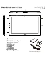
Iconia Tab 10
Brand: Acer Pages: 10
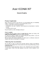
ICONIA W7
Brand: Acer Pages: 17
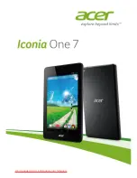
Iconia One 7 B1-730HD
Brand: Acer Pages: 52
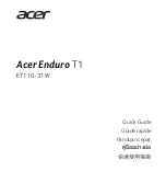
Enduro T1
Brand: Acer Pages: 44
Iconia One 8
Brand: Acer Pages: 48
1000
Brand: Accent Pages: 37
1400
Brand: Accent Pages: 42
M275
Brand: Gateway Pages: 78

T10+
Brand: Tobii Dynavox Pages: 32
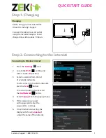
Tablet
Brand: Zeki Pages: 2
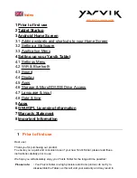
Tablet
Brand: Yarvik Pages: 20
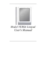
Versa LitePad
Brand: NEC Pages: 29
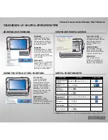
Toughbook U1 Ultra
Brand: Panasonic Pages: 2
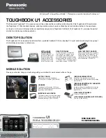
Toughbook U1 Ultra
Brand: Panasonic Pages: 2
CF-C1 Series
Brand: Panasonic Pages: 2
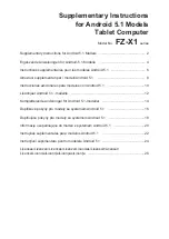
FZ-X1
Brand: Panasonic Pages: 27
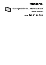
FZ-S1 Series
Brand: Panasonic Pages: 71
FZ-M1 Series
Brand: Panasonic Pages: 18


