Nokia N800 - Internet Tablet - OS 2007, Service Manual
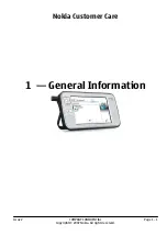
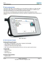
The Nokia N800, running OS 2007, is an innovative Internet Tablet designed for seamless web browsing and multimedia access. Enhance your experience by downloading the free product manual and service schematics from our website, allowing you to fully explore the capabilities of this exceptional device.
Share
Download


Reviews:
No comments
Related manuals for N800 - Internet Tablet - OS 2007
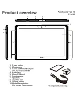
Iconia Tab 10
Brand: Acer Pages: 10
ICONIA W7
Brand: Acer Pages: 17
Iconia One 7 B1-730HD
Brand: Acer Pages: 52
Enduro T1
Brand: Acer Pages: 44
Iconia One 8
Brand: Acer Pages: 48
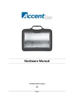
1000
Brand: Accent Pages: 37
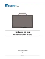
1400
Brand: Accent Pages: 42
M275
Brand: Gateway Pages: 78

T10+
Brand: Tobii Dynavox Pages: 32
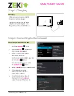
Tablet
Brand: Zeki Pages: 2
Tablet
Brand: Yarvik Pages: 20
Versa LitePad
Brand: NEC Pages: 29
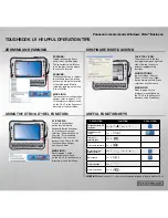
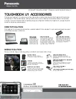
Toughbook U1 Ultra
Brand: Panasonic Pages: 2
Toughbook U1 Ultra
Brand: Panasonic Pages: 2
CF-C1 Series
Brand: Panasonic Pages: 2
FZ-X1
Brand: Panasonic Pages: 27
FZ-S1 Series
Brand: Panasonic Pages: 71
FZ-M1 Series
Brand: Panasonic Pages: 18


