background image

Wireless Transmitter

En

User's Manual

Printed in Japan

SB1L01(11)

6MWA0711-01

No reproduction in any form of this manual, in whole or in part 
(except for brief quotation in critical articles or reviews), may be 
made without written authorization from NIKON CORPORATION.

Summary of Contents for WT-5

Page 1: ...Manual Printed in Japan SB1L01 11 6MWA0711 01 No reproduction in any form of this manual in whole or in part except for brief quotation in critical articles or reviews may be made without written authorization from NIKON CORPORATION ...

Page 2: ...less network Once a connection has been established you can 1 Upload existing photos and movies 2 Take or browse photos remotely FTP upload Image transfer See the Network Guide 041 ftp server Computer See the Network Guide 015 Camera control HTTP server Camera Control Pro 2 See the Network Guide 019 See the Network Guide 022 iPhone Computer ...

Page 3: ...En_01 iii See Wireless Connections 05 for more information 3 Control multiple cameras Synchronized release See the Network Guide 045 ...

Page 4: ...ce Copyright 2011 Apple Computer Inc All Rights Reserved This file contains Original Code and or Modifications of Original Code as defined in and that are subject to the Apple Public Source License Version 2 0 the License You may not use this file except in compliance with the License Please obtain a copy of the License at http www opensource apple com license apsl and read it before using this fi...

Page 5: ...on A Cut power immediately in the event of malfunction Should you notice smoke or an unusual smell coming from the equipment immediately unplug the AC adapter and remove the battery taking care to avoid burns Continued operation could result in injury After removing the battery take the equipment to a Nikon authorized service representative for inspection A Do not use in the presence of flammable ...

Page 6: ...r disable the wireless LAN feature This is because WT 5 may be close to people using medical devices including cardiac pacemakers or rearing aids and have bad influences on the medical devices Turn off this product or turn of all wireless communication functions such as wireless LAN where medical institutions prohibit use of this product Turn off this product or turn of all wireless communication ...

Page 7: ...g from the use of this product While every effort has been made to ensure that the information in these manuals is accurate and complete we would appreciate it were you to bring any errors or omissions to the attention of the Nikon representative in your area address provided separately This product which contains encryption software developed in the United States is controlled by the United State...

Page 8: ...e in a residential installation This equipment generates uses and can radiate radio frequency energy and if not installed and used in accordance with the instructions may cause harmful interference to radio communications However there is no guarantee that interference will not occur in a particular installation If this equipment does cause harmful interference to radio or television reception whi...

Page 9: ...s are absolutely safe Low power Wireless devices emit low levels of radio frequency energy RF in the microwave range while being used Whereas high levels of RF can produce health effects by heating tissue exposure of low level RF that does not produce heating effects causes no known adverse health effects Many studies of low level RF exposures have not found any biological effects Some studies hav...

Page 10: ...re is no proof however that these low power wireless devices are absolutely safe Low power Wireless devices emit low levels of radio frequency energy RF in the microwave range while being used Whereas high levels of RF can produce health effects by heating tissue exposure of low level RF that does not produce heating effects causes no known adverse health effects Many studies of low level RF expos...

Page 11: ... product is to be collected separately This product is designated for separate collection at an appropriate collection point Do not dispose of as household waste For more information contact the retailer or the local authorities in charge of waste management Declaration of Conformity A copy of the original DoC for our products as it relates to R TTE can be found at the following website http imagi...

Page 12: ...els 2 4 GHz band 5 GHz band WT 5 The 31 countries of the EU EFTA Austria Belgium Bulgaria Cyprus the Czech Republic Denmark Estonia Finland France Germany Greece Hungary Iceland Ireland Italy Latvia Liechtenstein Lithuania Luxembourg Malta the Netherlands Norway Poland Portugal Romania Slovakia Slovenia Spain Sweden Switzerland the United Kingdom Australia Japan New Zealand South Africa 1 13 36 64...

Page 13: ...100 140 149 165 WT 5 Indoor Infrastructure Ad hoc Outdoor Infrastructure Prohibited Prohibited Ad hoc Prohibited WT 5A Indoor Infrastructure Ad hoc Prohibited Outdoor Infrastructure Prohibited Ad hoc Prohibited WT 5B Indoor Infrastructure Ad hoc Outdoor Infrastructure Ad hoc WT 5C Indoor Infrastructure Ad hoc Outdoor Infrastructure Ad hoc ...

Page 14: ...T 5 4 Wireless Connections 5 Step 1 Getting Ready 7 Step 2 Selecting the WT 5 8 Step 3 The Connection Wizard 8 Step 4 Network Settings 16 Copying Profiles 22 Appendices 25 Accessing the Camera 25 Creating Network Profiles with the Wireless Transmitter Utility 33 Troubleshooting 45 Specifications 46 Index 48 TableofContents ...

Page 15: ...and WT 5A B C D is in the number of channels supported unless otherwise stated all refercences to the WT 5 also apply to the WT 5A B C D Symbols and Conventions The following symbols and conventions are used throughout this manual Background Knowledge This manual assumes basic knowledge of ftp servers and local area networks LANs For more information on installing configuring and using devices in ...

Page 16: ...mation tips answers to frequently asked questions FAQs and general advice on digital imaging and photography Additional information may be available from the Nikon representative in your area See the following URL for contact information http imaging nikon com Illustrations The camera shown in this manual is a D4 Save where otherwise noted all software and operating system dialogs messages and dis...

Page 17: ...th a master camera A FTP Servers Servers can be configured using standard ftp services such as IIS Internet Information Services available with supported operating systems See the network guide supplied with the camera for more information Image transfer and camera control do not support connection to computers on other networks via a router Internet ftp connections and ftp servers running third p...

Page 18: ...camera peripheral connector e Rotate the locking wheel to lock the WT 5 in place D Power Source The WT 5 is not equipped with a battery or power switch Power is supplied from the camera A Connection Status Connection status is shown by the LED on the WT 5 LED LED Status K glows green Connected H flashes green Ready to connect H flashes yellow Error ...

Page 19: ...a control HTTP server Install the Wireless Transmitter Utility Step 1 Ready the camera and WT 5 07 Step 2 Select the WT 5 08 Step 3 Run the connection wizard 08 Step 4 Adjust network settings 016 FTP Upload 016 Image Transfer Camera Control and HTTP Server 019 Configure the server Pair the camera and computer Connect ...

Page 20: ...ansfer or camera control mode See the network guide supplied with the camera for installation instructions A Synchronized Release Network profiles are not required in synchronized release mode For more information see the network guide supplied with the camera A Infrastructure and Ad Hoc Modes Wireless networks may be either infrastructure or ad hoc Infrastructure mode Connection via a wireless LA...

Page 21: ...the camera off and insert a memory card do not turn the camera off while data are being transferred to the computer This step can be omitted in camera control mode 0ii 2 Attach the WT 5 04 3 Turn the camera on Rotate the power switch to turn the camera on D Removing the WT 5 Turn the camera off remove the WT 5 and replace the peripheral connector cover Power switch ...

Page 22: ...tep 3 The Connection Wizard Follow the on screen instructions to create a network profile 1 Display network profiles In the network menu highlight Network settings and press 2 to display the profiles list and other network settings 2 Select Create profile Highlight Create profile and press 2 Note that if the list already contains nine profiles you will need to delete an existing profile using the ...

Page 23: ...s 2 to start the connection wizard 4 Choose a connection type 03 Highlight a connection type and press 2 5 Name the new network profile Enter the name that will appear in the profile list and press J to use the default name press J without making any changes Profile names can be up to 16 characters long ...

Page 24: ... field will be deleted To delete the character under the cursor press the O Q button To move the cursor to a new position hold W and press 4 or 2 To complete entry and close the dialog press J To exit without completing text entry press G Searchforwireless network Choose from a list of networks detected by the camera 011 Push button WPS Choose for wireless LAN access points with push button WPS 01...

Page 25: ... to the left of the ID Highlight a network and press J if the desired network is not displayed press X to search again 2 Enter the encryption key Enter the encryption key and press J if the network uses open authentication this dialog will not be displayed proceed to Step 3 h Signal encrypted j i Infrastructure ad hoc A Hidden SSIDs Networks with hidden SSIDs are indicated by blank entries in the ...

Page 26: ...sh button WPS in Step 6 on page 10 if the wireless LAN access point uses push button WPS 1 Press the WPS button on the wireless LAN access point For more information see the documentation provided with the wireless LAN access point 2 Press J button on the camera The camera will connect to the access point automatically If you chose FTP upload go to page 16 If you chose Image transfer Camera contro...

Page 27: ... step The message at right is displayed when a connection is established Your next step depends on the connection type selected in Step 4 on page 9 If you chose FTP upload go to page 16 If you chose Image transfer Camera control or HTTP server go to page 19 ...

Page 28: ...oint For more information see the documentation provided with the wireless LAN access point 2 Press J button on the camera The camera will connect to the access point automatically 3 Choose your next step The message at right is displayed when a connection is established Your next step depends on the connection type selected in Step 4 on page 9 If you chose FTP upload go to page 16 If you chose Im...

Page 29: ...er the SSID Enter a network name SSID and press J The default name is WT followed by the MAC address of the WT 5 2 Enter the encryption key Enter an encryption key and press J the default key is nikon Your next step depends on the connection type selected in Step 4 on page 9 If you chose FTP upload go to page 16 If you chose Image transfer Camera control or HTTP server go to page 19 ...

Page 30: ...tomatically Enter manually When prompted enter an IP address and subnet mask by pressing 4 and 2 to highlight segments and 1 and 3 to change Press J to proceed when entry is complete 2 Confirm the IP address The camera IP address will be displayed as shown at right press J 3 Choose the server type Highlight FTP or SFTP secure ftp and press 2 A Firewall Settings Ports 21 and 32768 through 61000 are...

Page 31: ...Select this option if the server does not require a user ID or password Enter a user ID Enter a user ID and password when prompted and press J A MAC Address Filtering If the network using MAC address filtering the filter must be supplied with the MAC address of the WT 5 After attaching the WT 5 to the camera choose Network Options MAC address from the camera setup menu and note the MAC address ...

Page 32: ... option to upload pictures to another of the folders existing on the server Enter a folder name and path when prompted and press J 7 Exit the wizard Highlight one of the following options and press J Connect and exit wizard Save the new network profile and connect to the server Exit wizard Save the new network profile and exit For more information on using wireless networks see the Network Guide s...

Page 33: ...ettings can not be copied to a computer running Mac OS X and that infrastructure settings can not be copied under Mac OS X 10 4 and 10 5 and that network settings for other operating systems may be overwritten A Routers Connection to computers on other networks via a router is supported only when HTTP server is selected A MAC Address Filtering If the network using MAC address filtering the filter ...

Page 34: ...ceed when entry is complete 3 Confirm the IP address The camera IP address will be displayed as shown at right press J If Image transfer or Camera control is selected proceed to Step 4 otherwise proceed to Step 7 4 Connect the camera to the computer When prompted connect the camera to the computer using the USB cable supplied with the camera A Firewall Settings Image transfer and camera control mo...

Page 35: ...Disconnect the camera The message at right will be displayed when pairing is complete Disconnect the USB cable 7 Exit the wizard Highlight one of the following options and press J Connect and exit wizard Save the new network profile and connect to the network Exit wizard Save the new network profile and exit For more information on using wireless networks see the Network Guide supplied with the ca...

Page 36: ...hen profiles are copied in infrastructure mode 1 Enable copying When the connection wizard prompts you to choose whether to copy the profile to a computer 019 highlight Yes and press 2 2 Connect the camera to the computer When prompted connect the camera to the computer using the USB cable supplied with the camera 3 Start the Wireless Transmitter Utility When prompted start the copy of the Wireles...

Page 37: ... automatically pair the camera and computer 5 Disconnect the camera The message at right will be displayed when the process is complete Disconnect the USB cable The options shown at right will be displayed choose an option to exit the wizard D Ad Hoc Mode The camera will not automatically connect in ad hoc mode Choose the network profile on the computer before connecting ...

Page 38: ...En_01 24 ...

Page 39: ...n and follow the steps below to access the camera from a computer or iPhone Windows 7 025 Windows Vista 027 Windows XP 029 Mac OS X 030 iPhone 031 Windows7 1 Click the Internet Access icon in the taskbar 2 Select the network name SSID and click Connect AccessingtheCamera ...

Page 40: ...En_01 26 3 Enter the encryption key and click OK 4 Confirm that the connection is successful An icon is displayed in the taskbar when a connection is established ...

Page 41: ...En_01 27 WindowsVista 1 Click the Start orb and select Connect to 2 Select the network name SSID and click Connect ...

Page 42: ...En_01 28 3 Enter the encryption key and click Connect 4 Click Close 5 Confirm that the connection is successful The icon shown at right is displayed in the taskbar when a connection is established ...

Page 43: ...nnection icon in the taskbar 2 Select the network name SSID and click Connect 3 Enter the encryption key and click Connect 4 Confirm that the connection is successful The icon shown at right is displayed in the taskbar when a connection is established ...

Page 44: ...elect Turn Wi Fi On 2 Click the Wi Fi icon and select the network name SSID 3 Enter the encryption key and click Join 4 Confirm that the connection is successful The icon shown at right is displayed in the taskbar when a connection is established ...

Page 45: ...En_01 31 iPhone 1 Tap Settings in the iPhone Home screen 2 Tap Wi Fi 3 Tap On and select the network name SSID ...

Page 46: ...En_01 32 4 Enter the encryption key and tap Join 5 Confirm that the connection is successful A check appears next to the network name when a connection is established ...

Page 47: ...onnect the camera Use the USB cable supplied with the camera to connect the camera to the computer as shown below 2 Turn the camera on Rotate the power switch to turn the camera on 3 Start the Wireless Transmitter Utility Windows Double click the Wireless Transmitter Utility icon on the desktop Mac OS Click the Wireless Transmitter Utility icon in the Dock Power switch ...

Page 48: ...En_01 34 4 Click Next 5 Select WT 5 and click Next ...

Page 49: ...log at right will be displayed click the button and choose a destination If you do not choose another destination pictures will be uploaded to Windows Users user name Pictures Wireless Transmitter Utility Mac OS Users user name Wireless Transmitter Utility To display pictures in ViewNX 2 when the connection with the WT 5 is terminated select Show it with ViewNX 2 This option is only available if V...

Page 50: ...ect Add new profile and click Next 8 Enter the following information and click Next Profile name Enter a name of up to 16 characters Connection type Choose FTP upload Image transfer Camera control or HTTP server 0ii ...

Page 51: ...En_01 37 9 Select Manual setup and click Next ...

Page 52: ...cture network recommended choose the network from the pull down menu and click Next to proceed to Step 12 042 Automatic setup is not available for connection to networks for which a profile already exists or to third party wireless LAN adapters networks using static IP addresses or computers running Mac OS X or that are not configured for connection to a wireless LAN access point ...

Page 53: ...nnel automatically Authentication The authentication used on the network Choose from open system shared key WPA PSK and WPA2 PSK infrastructure or open system and shared key ad hoc Encryption The encryption used on the network The options available depend on the authentication used Open None 64 or 128 bit WEP WPA PSK TKIP AES Shared 64 or 128 bit WEP WPA2 PSK AES Encryption key If the network uses...

Page 54: ...En_01 40 Key index If WEP64 or WEP128 is selected for Encryption choose a key index the default index is 1 A key index is not required when None is selected ...

Page 55: ...he following information IPaddress Subnetmask Enter an IP address and subnet mask for the WT 5 Choose an IP address that is not already assigned to other devices on the network Default gateway If the network requires a gateway address select this option and enter the address supplied by the network administrator DNS Server If a Domain Name Server exists on the network select this option and enter ...

Page 56: ...rver port Enter the port number for the ftp server FTP path Choose the folder to which pictures will be uploaded Server type Choose FTP or SFTP Anonymous login Select this option for anonymous login or leave this option unchecked to supply a User ID and Password Use proxy server If a proxy server is required for ftp select this option and enter the server name and port number for the proxy server ...

Page 57: ...En_01 43 13 Confirm that settings are correct and click Next 14 Select Finish wizard and click Next 15 Turn the camera off and disconnect the USB cable ...

Page 58: ...in the camera setup menu then highlight Network settings and press 2 to display the profiles list 18 Select the new network profile Highlight the new network profile and press 2 to return to the network menu 19 Select Network connection Highlight Network connection and press 2 20 Select Enable Highlight Enable and press 2 to connect to the network ...

Page 59: ... firewall settings 20 The camera displays a wireless error Confirm that the host and wireless LAN adapter are on Confirm that there are no obstacles between the WT 5 and the adapter Check settings for the host and or wireless LAN adapter and adjust camera settings appropriately 5 The camera displays a memory card error Confirm that the card is properly inserted 7 Transfer is interrupted before all...

Page 60: ...48 52 56 60 64 ch 5745 5825 MHz 149 153 157 161 165 ch 2412 2462 MHz 1 11 ch WT 5B 5180 5320 MHz 36 40 44 48 52 56 60 64 ch 2412 2472 MHz 1 13 ch WT 5C 5745 5825 MHz 149 153 157 161 165 ch 2412 2472 MHz 1 13 ch WT 5D 2412 2462 MHz 1 11 ch Approximate range line of sight Approximately 180 m 590 5 ft Data rates IEEE 802 11a g 6 9 12 18 24 36 48 and 54 Mbps IEEE 802 11b 1 2 5 5 and 11 Mbps IEEE802 11...

Page 61: ...l data rates according to IEEE standard Actual rates may differ Data transfer protocols PTP IP ftp sftp Power consumption 1 2 W maximum Operating environment Temperature 0 40 C 32 104 F Humidity Less than 85 no condensation Weight Approximately 27 g 0 96 oz body only Dimensions W H D Approximately 32 0 mm 41 5 mm 30 0 mm 1 3 in 1 7 in 1 2 in ...

Page 62: ...ll 16 20 Folder 18 35 FTP server 3 5 16 42 FTP upload 3 5 16 H HTTP server 3 5 19 I Image transfer 3 5 19 Infrastructure 6 38 IP address 16 20 41 L LED 4 M MAC address 17 19 Memory card 7 P PASV mode 42 PIN entry WPS 10 14 Port 16 20 42 PTP IP 47 Push button WPS 10 12 S Search for wireless network 10 11 SSID 11 15 39 Synchronized release 3 6 T Text entry 10 W Wireless LAN access point 6 11 Wireles...

Page 63: ...En_01 ...
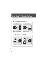
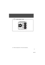
Page 64: ...Manual Printed in Japan SB1L01 11 6MWA0711 01 No reproduction in any form of this manual in whole or in part except for brief quotation in critical articles or reviews may be made without written authorization from NIKON CORPORATION ...

Reviews: