background image

M232 E 

04.7.CF.3

Wafer Loader NWL860 Series

IFC Function

(SECS Communications)

Specifications

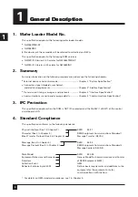
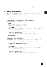
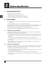
Summary of Contents for NWL860 Series

Page 1: ...M232 E 04 7 CF 3 Wafer Loader NWL860 Series IFC Function SECS Communications Specifications ...

Page 2: ...ader Purpose This specification described the requirements for serial communications between the model NWL860TMB SP or NWL860INX and the customer s computer The specification has the following purposes Online Remote Control Mode All operations except those involving the stage and the joystick can be performed with external devices including PCs after communications have been set up correctly Onlin...

Page 3: ......

Page 4: ...er 3 Interface Specification 8 1 Physical Interface Common to all ports 8 1 1 Interactive Signal Connection Circuit 8 1 2 Connector 8 1 3 Data Rate 8 1 4 Pin Connection 8 1 5 Synchronization System 8 1 6 Transmission 8 1 7 Connection 8 2 Character 9 2 1 Character Length 9 2 2 Format 9 2 3 Start Bit 9 2 4 Data Bit 9 2 5 Parity Bit 9 2 6 Stop Bit 9 3 Block Transfer Protocol 10 3 1 System 10 3 2 Tran...

Page 5: ...e 23 1 4 Saving of Settings 24 2 List of SECS Messages to and from the Host 25 3 Functions Implemented in Communications with Host and Scenario 27 3 1 Establishment of Communications 27 3 2 Online Check 27 3 3 Sample File Management 27 3 4 Carrier File Management 28 3 5 Equipment Information Management 29 3 6 Event Report 29 3 7 Control Mode Selection 31 3 8 Remote Control 33 3 9 Alarm Management ...

Page 6: ... 77 5 21 ECID 77 5 22 ECMAX 80 5 23 ECMIN 80 5 24 ECNAME 80 5 25 ECV 80 5 26 EDID 81 5 27 ERACK 81 5 28 ERRW7 81 5 29 GRANT6 81 5 30 LENGTH 81 5 31 LRACK 82 5 32 HCACK 82 5 33 MDLN 82 5 34 MEXP 82 5 35 MHEAD 83 5 36 OFLACK 83 5 37 ONLACK 83 5 38 PPARM 83 5 39 PPGNT 83 5 40 PPID 84 5 41 RCMD 84 5 42 RPTID 87 5 43 SEQNUM 87 5 44 SHEAD 87 5 45 SOFTREV 88 5 46 SV 88 5 47 SVID 88 5 48 SVNAME 89 5 49 UN...

Page 7: ...pter 4 Communications Specification 3 IFC Protection This specification applies when the ROM is NOT IFC protected and the DipSW 1 of SW1 of the control circuit board is ON 4 Standard Compliance This specification conforms to the following standards For details on GEM standard compliance see 1 in Chapter 5 Physical Interface See 1 in Chapter 3 Character See 2 in Chapter 3 Block Transfer Protocol Se...

Page 8: ...fferent ROM versions A prompt for conversion appears in the display screen Select Cnvrt The conversion starts Upon completion the Welcome NWL860 screen the screen shown at startup is displayed NWL860TMB SP The circuit board and internal cable required for communications are built in Use ROMs for NWL3R IFC version 2 30 or later NWL860TMBs other than type SP lack the required circuit board and inter...

Page 9: ...ntrol knob settings except the joystick emergency stop switch and function switch for turning off communications are disabled If any of these switches is turned on the inhibit buzzer will sound The control mode is switched to offline host offline mode by a command from the host The control mode is also switched to offline host offline mode if the host does not reply and a timer s set time elapses ...

Page 10: ...uipment is ready for communications but the host rejects communications with the equipment or the connection fails Equipment Offline State The equipment is in offline mode 3 External Connection This specification is based on three different connection methods Communications with Host Communications with Indexer Communications with Host and Indexer Host Equipment COM2 NWL Indexer INX Host Equipment...

Page 11: ...ded jack screw lock 1 3 Data Rate 300 1200 2400 4800 9600 default baud 1 4 Pin Connection 1 5 Synchronization System Start stop system asynchronous system 1 6 Transmission Half duplex transmission 1 7 Connection Point to point connection Interface Specification FG TXD RXD RTS CTS DSR SG CD DTR NWL PC Connection Shielding D sub25pin male D sub9pin female M2 6 Screw 4 40 Screw Frame Frame NWL PC The...

Page 12: ... Interface Specification 3 2 Character 2 1 Character Length 10 bits 2 2 Format 2 3 Start Bit 1 bit 0 2 4 Data Bit 8 bits 2 5 Parity Bit N A 2 6 Stop Bit 1 bit 1 Data Bit Start Bit Stop Bit LSB 1 MSB 8 2 3 4 5 6 7 ...

Page 13: ...ay screen with the precision shown below Typical Value Code 9600 101 65H 0 5 S 10 S 45 S 45 S 3 Serial communications speed Equipment identification number Error detected in characters No protocol response determination No reply message determination Error detected in a multi block message The maximum number of retries BAUD DEVID T1 T2 T3 T4 RTY Function Baud rate Device ID Character time out Prot...

Page 14: ...bers of the header and the message data without codes The upper digit byte is sent before the lower digit byte 4 6 Header 4 6 1 Format Message length 1 byte Header 10 bytes Message data max 244 bytes Checksum 2 bytes Messages consists of the following blocks Time Upper device ID Lower device ID Upper message ID Lower message ID Upper block No Lower block No System byte 8 7 6 5 4 3 2 1 1 2 3 4 5 6 ...

Page 15: ... S5 S6 S7 S8 S9 S10 Equipment status Equipment status and diagnosis Status of the material Control of the material Exception report Data gathering Control of manufacturing program Control program System error Terminal service Message Type 4 6 7 Function Code The Function code represents the specific message contained in a stream Several code numbers are reserved by the SECS The code F0 is defined ...

Page 16: ...locks follow E 1 No blocks follow 4 6 11 Multi Block When message data consists of more than one block the data is referred to as a multi block message One multi block message can contain up to 32767 blocks a total length of 7 99 Mbytes The first block of a multi block message is numbered 1 All subsequent blocks are numbered in order with each assigned number incremented by one from the preceding ...

Page 17: ...m header or list list header 4 7 2 Item Header Format Item header consists of format byte upper 6 bits and length byte lower 2 bits 4 7 3 Format Byte Format byte consists of item format code and length byte count 4 7 4 Item Format Code Defines the format of data DATA Item or List DATA Item or List 8 7 6 5 4 3 2 1 Item Format Code Length Byte Count MSB Data Length Byte LSB MSB Data Length Byte LSB ...

Page 18: ...data consists of data in different formats The format of the list header is the same as that of the item header Individual component data are defined by the item header 4 7 8 Examples of Item and List a Item containing one binary code 10101010 bit 87654321 00100001 Item with length byte 1 00000001 Byte length 1 10101010 Data byte b Item containing three ASCII characters A B and C 01000001 Item ASC...

Page 19: ...ment device ID 0487H to the host to an inquiry into online status 00011100 Message length 28 bytes 10000100 From host Device ID to equipment 10000111 0487H 00000001 Not expecting response message 00000010 S1F2 10000000 Single block 00000001 Block No 1 00000000 System byte 0 00000001 1 00000000 0 00000001 1 00000001 List 00000010 2 elements 01000001 ASCII 1 byte 00000110 6 bytes 00110001 MDLN 1 001...

Page 20: ...s detected the data is ignored 5 2 Handling of Multi Block Multi block messages are handled at both the transmitting and receiving ends 5 3 Multi Transaction The NWLs do not apply to multi transactions interleaving messages 5 4 Size of Incoming Message An incoming message should not exceed 17 blocks 5 5 Size of Outgoing Message An outgoing message should not exceed 17 blocks ...

Page 21: ...sfer Protocol Parameter in this chapter 6 2 Contention Request to send T2 T2 T3 T2 T1 ENQ EOT Message length DATA DATA Checksum Checksum ACK ENQ EOT Message length DATA T2 T1 T2 Acknowledge Send a reply Ready to receive Equipment Host ENQ EOT Message ACK ENQ EOT Message ACK ENQ Ready to receive Acknowledge Send a reply if required Resend contention ...

Page 22: ......

Page 23: ... check Error message Control started by operator Documentation Additional Capabilities Establishment of Communications Selecting the dynamic event report setting Variable data collection Trace data collection Status data collection Alarm management Remote control Equipment constant Process program management Material movement Equipment terminal service Clock Limit monitoring Spooling Control start...

Page 24: ...ssage Variable ECID 028 in this chapter DISABLE ENABLE NOT COMMUNICATING COMMUNICATING c State DISABLE ENABLE NOT COMMUNICATING COMMUNICATING Communications between host and equipment are disabled This setting has two sub states COMMUNICATING and NOT COMMUNICATING No messages except S1F13 F14 or S9Fx may be transmitted Full communications established Explanation HOST WL S1F13 S1F14 DISABLE or ENAB...

Page 25: ...e the equipment can be controlled through exchange of messages with the host The equipment is controlled directly by operators The host can control a range of equipment functions via the communications interface Explanation c Communications State Equipment OFFLINE Host OFFLINE ONLINE The OFFLINE indication appears in the option setting screen and no indication appears in the initial screen The OFF...

Page 26: ...he Local key in the fixed screen Status Variable Controlling Current Control State See 5 Definition of Message Variable in this chapter Operator Command Event in Remote State See 5 Definition of Message Variable in this chapter Event in State Transition Inquiries for control state S1F3 F4 operator command event reports S6F11 F12 and state transition event reports S6F11 F12 may be available through...

Page 27: ... Communications Control Event Report Alarm Management Time seconds within which S1F13 must be transmitted once communications are established Online Offline Equipment Online Online Establishment Try Host Offline Enable or disable event transmission ID attached to the report and VID representing the attributive value of the report Report ID linked to the collection event Enable or disable alarm tra...

Page 28: ...LA S H E Stream 2 Equipment Control and Diagnosis S2 F13 Equipment constant request ECR S H E REPLY F14 Equipment constant data ECD S M H E F15 New equipment constant send ECS S H E REPLY F16 New equipment constant acknowledge ECA S H E F29 Equipment constant name list request ECNR S H E REPLY F30 Equipment constant name list ECN S H E F33 Define report DR S M H E REPLY F34 Define report acknowled...

Page 29: ...rogram load grant PPG S H E F19 Current EPPD request RER S H E REPLY F20 Current EPPD data RED S M H E F23 Formatted process program send FPS S M H E REPLY F24 Formatted process program acknowledge FPA S H E F25 Formatted process program request FPR S H E REPLY F26 Formatted process program data FPD S M H E F27 Process program verification send PVS S H E REPLY F28 Process program verification ackn...

Page 30: ...ost Equipment Comment Communications state ENABLE S1F13 Requests to establish communications Acknowledges request to establish S1F14 Transmits COMMACK 0 in reply communications For scenarios involving time outs and negative acknowledgements refer to SEMI E30 4 1 5 2 3 2 Online Check Checks the line or equipment status The online check is performed by the host and used for periodic line check heart...

Page 31: ... Acknowledges inquiry for process program loading Transmits formatted process program S7F23 S7F24 Acknowledges formatted process program S7F27 Transmits process program verification Acknowledges process program verification S7F28 3 3 3 PPID List Transmission The equipment transfers PPID information to the host for all host sample and carrier files Scenario Process program directory request Message...

Page 32: ...tting Data Request from Host The equipment transmits the equipment constant selected and transmitted by the host Scenario Equipment constant request by host Message S2F13 F14 Comment Host Equipment Comment Requests equipment constant S2F13 S2F14 Transmits equipment constant data 3 5 3 Equipment Setting Definition Request by Host The equipment transmits the maximum minimum and default values for th...

Page 33: ...3 Event Report Setting The host defines the report defines a data group as a report Single block transmission The host links the above report to the collection event Single block transmission The host defines the collection event as enabled or disabled Single block transmission During communications with the NWL the host can define up to eight 0 7 reports One report can contain up to five variable...

Page 34: ...tted by Host The operator switches equipment control mode from offline to online Scenario Online permitted by host Message S1F1 F2 S6F11 F12 Comment Host Equipment Comment S1F1 Request to switch to online mode Grants request to switch to online mode S1F2 S6F11 Transmits event report control state is local remote Acknowledges S6F12 3 7 2 Switching to Online by Equipment Operator Rejected by Host Sc...

Page 35: ...vent report control state is local Acknowledges S6F12 3 7 6 Switching to Offline by Host Scenario Offline selected by host Message S1F0 F15 F16 S6F11 F12 Comment Host Equipment Comment Request to switch to offline mode S1F15 IF The equipment is offline THEN S1F10 Rejects request ELSE S1F16 Accepts request S6F11 Transmits event report host offline Acknowledges S6F12 END_IF 3 7 7 Switching to Online...

Page 36: ...he host occurs the equipment sends notification to the host of the alarm Alarm notification is transmitted separately from event reports 3 9 1 Alarm Enable Disable Setting The host sets the alarms for which the equipment should transmit notification Scenario Alarm enable disable Message S5F3 F4 Comment Host Equipment Comment Transmits the alarm enable disable setting S5F3 S5F4 Acknowledges the set...

Page 37: ...cations detected by the equipment 3 11 1 Message Error by Unrecognized Device ID Scenario Message error by unrecognized device ID Message S9F1 Comment Host Equipment Comment Transmits a message SxFx Detects unrecognized device ID S9F1 Notifies the host that an unrecognized device ID is detected 3 11 2 Message Error by Unrecognized Stream Type Scenario Message error by unrecognized stream type Mess...

Page 38: ... S9F9 Notifies the host that transaction time out has occurred 3 11 6 Message Error by Excessive Data Size Scenario Message error involving excessive data size Message S9F11 Comment Host Equipment Comment Transmits a message SxFx Detects data longer than can be processed by the equipment in message from host S9F11 Notifies the host of excessive data length 3 11 7 Communications Error by Communicat...

Page 39: ...hether the equipment is operating online When receiving function 0 the host cannot communicate with the equipment Structure HEADER Required 4 Detailed Message Format 4 1 Stream 1 1 On Line Data Function S F 2 S D REPLY H E M S Abbr Declares that the equipment is operating online Structure HEADER L 2 1 MDLN 2 SOFTREV ...

Page 40: ...ies the equipment for the selected status variable value Structure HEADER L n 1 SVID1 n SVIDn Required 1 Selected Equipment Status Data Function S F 4 S SSD REPLY H E M S Abbr The equipment reports SVID values by order of request The host should retain a record of the SVID whose values were requested Structure HEADER L n 1 SV1 n SVn ...

Page 41: ... queries the equipment to check status variables Structure HEADER L n 1 SVID1 n SVIDn Required 1 Status Variable Name list Reply Function S F 12 S SVNRR REPLY H E M S Abbr The equipment reports the name and unit of the requested status variables Structure HEADER L n 1 L 3 1 SVID1 2 SVNAME1 3 UNITS1 n L 3 1 SVIDn 2 SVNAMEn 3 UNITSn ...

Page 42: ...gain after completion or interruption of communications this command establishes the start of a new communications session Structure HEADER L 2 1 MDLN 2 SOFTREV Required 1 Establish Communication Request Acknowledge Function S F 14 S CRA REPLY H E M S Abbr Accepts or denies the Establish Communications Request S1F13 Structure HEADER L 2 1 COMMACK 2 L 2 1 MDLN 2 SOFTREV ...

Page 43: ...est OFF LINE Function S F 15 S ROFL REPLY H E M S Abbr The host asks the equipment to shift to offline status Structure HEADER Required 1 OFF LINE Acknowledge Function S F 16 S OFLA REPLY H E M S Abbr Transmits OK or NG to S1F15 Structure HEADER OFLACK ...

Page 44: ...uest ON LINE Function S F 17 S RONL REPLY H E M S Abbr The host asks the equipment to shift to online status Structure HEADER Required 1 ON Line Acknowledge Function S F 18 S ONLA REPLY H E M S Abbr Transmits OK or NG to S1F17 Structure HEADER ONLACK ...

Page 45: ... value servo gain limit for alarm data collection mode and other values that do not vary significantly constant Structure HEADER L n 1 ECID1 2 ECIDn Required 2 Equipment Constant Data Function S F 14 S ECD REPLY H E M S Abbr Transmits constants by order of request in response to F13 Structure HEADER L n 1 ECV1 2 ECV2 n ECVn 4 2 Stream 2 ...

Page 46: ...nction S F 15 S ECS REPLY H E M S Abbr Changes one or more equipment constants Structure HEADER L n 1 L 2 1 ECID1 2 ECV1 n L 2 1 ECIDn 2 ECVn Required 2 New Equipment Constant Acknowledge Function S F 16 S EAC REPLY H E M S Abbr Transmits OK or NG to S2F15 Structure HEADER EAC ...

Page 47: ...t constants currently valid for the equipment Structure HEADER L n 1 ECID1 n ECIDn Required 2 Equipment Constant Name list Function S F 30 M ECN REPLY H E M S Abbr Replies to S2F29 Structure HEADER L n n represents the number of equipment constant names 1 L 6 1 ECID1 2 ECNAME1 3 ECMIN1 4 ECMAX1 5 ECDEF1 6 UNITS1 n L 6 1 ECIDn 2 ECNAMEn 3 ECMINn 4 ECMAXn 5 ECDEFn 6 UNITSn ...

Page 48: ...on the equipment Structure HEADER L 2 1 DATAID 2 L a 1 L 2 1 RPTID1 2 L b 1 VID1 b VIDb a L 2 1 RPTIDa 2 L c 1 VID1 c VIDc Required 2 Define Report Acknowledge Function S F 34 S DRA REPLY H E M S Abbr Acknowledgement or error If an error state is detected all messages are rejected Partial changes are not permitted Structure HEADER DRACK ...

Page 49: ...nt ID CEID Structure HEADER L 2 1 DATAID 2 L a 1 L 2 1 CEID1 2 L b 1 RPTID1 b RPTIDb a L 2 1 CEIDa 2 L c 1 RPTID1 c RPTIDc Required 2 Link Event Report Acknowledge Function S F 36 S LERA REPLY H E M S Abbr Transmits acceptance or error If an error state is detected all messages are rejected Partial changes are not permitted Structure HEADER LRACK ...

Page 50: ...s of reports on the collected event ID CEIDs Structure HEADER CEED L n n represents the number of CEID 1 CEID1 n CEIDn Required 2 Enable Disable Event Report Acknowledge Function S F 38 S EERA REPLY H E M S Abbr Transmits acceptance or error If an error state is detected all messages are rejected Partial changes are not permitted Structure HEADER ERACK ...

Page 51: ...r of parameters 1 L 2 1 CPNAME1 2 CPVAL1 n L 2 1 CPNAMEn 2 CPVALn Required 2 Host Command Acknowledge Function S F 42 S HCA REPLY H E M S Abbr Transmits a host command or error If the command is not accepted due to one or more incorrect parameters the equipment returns a list of incorrect parameters including parameter names and reasons for inappropriateness Structure HEADER L 2 1 HCACK 2 L n 1 L ...

Page 52: ...anceled This message is transmitted when an alarm is activated or canceled The errors that cannot be recovered and the caution flag are not required to have corresponding release messages Structure HEADER L 3 1 ALCD 2 ALID 3 ALTX Required 5 Alarm Report Acknowledge Function S F 2 S ARA REPLY H E M S Abbr Transmits OK or NG to S5F1 Structure HEADER ACKC5 4 3 Stream 5 ...

Page 53: ...the enable bit of an alarm report from the equipment Using this bit the equipment determines whether to send an alarm report to the host Some alarms may not be controlled by this method Structure HEADER L 2 1 ALED 2 ALID Required 5 Enable Disable Alarm Acknowledge Function S F 4 S EAA REPLY H E M S Abbr Transmits OK or NG to S5F3 Structure HEADER ACKC5 ...

Page 54: ...LID1 ALIDn Required 5 List Alarm Request Function S F 6 S LAD REPLY H E M S Abbr Alarm list data This indicates the current alarm status alarm has occurred is being canceled It may contain more than one alarm data Structure HEADER L m 1 L 3 1 ALCD1 2 ALID1 3 ALTX1 m L 3 1 ALCDm 2 ALIDm 3 ALTXm When m 0 there is no alarm data When ALCDi or ALTXi item length is 0 there is no data for the alarm in qu...

Page 55: ... M S Abbr When a discrete type data report S6F11 requires multi block format this transaction must be performed before transmission Structure HEADER L 2 1 DATAID 2 DATALENGTH Required 6 Multi block Grant Function S F 6 S MBG REPLY H E M S Abbr Transmits OK or NG to S6F5 Structure HEADER GRANT6 4 4 Stream 6 ...

Page 56: ...ds a series of defined and linked enabled reports to the host as soon as an event occurs Structure HEADER L 3 1 DATAID 2 CEID 3 L a 1 L 2 1 RPTID1 2 L b 1 V1 b Vb a L 2 1 RPTIDa 2 L c 1 V1 c Vc Required 6 Event Report Acknowledge Function S F 12 S ERA REPLY H E M S Abbr Indicates acceptance or error Structure HEADER ACKC6 ...

Page 57: ...est The host queries the equipment for a series of given reports HEADER CEID Required 6 Event Report Data Function S F 16 M ERD REPLY H E M S Abbr Event report data The equipment transmits reports linked to the given CEID Structure HEADER L 3 1 DATAID 2 CEID 3 L a 1 L 2 1 RPTID1 2 L b 1 V1 b Vb a L 2 1 RPTIDa 2 L c 1 V1 c Vc ...

Page 58: ...Y H E M S Abbr The host requests defined reports from the equipment Structure HEADER RPTID Required 6 Individual Report Data Function S F 20 M IDR REPLY H E M S Abbr The equipment sends variable data defined for the given RPTID to the host Structure HEADER L n Number of variable data items 1 V1 n Vn ...

Page 59: ...E M S Abbr Used before process program transmission S7F3 F4 sent before loading or unloading of process programs Structure HEADER L 2 1 PPID 2 LENGTH Required 7 Process Program Load Grant Function S F 2 S PPG REPLY H E M S Abbr Grants permission to load process program Structure HEADER PPGNT 4 5 Stream 7 ...

Page 60: ...e current equipment process program directory EPPD a list of the process program PPID stored by the equipment Structure HEADER Required 7 Current EPPD Data Function S F 20 M RED REPLY H E M S Abbr Transmits the current EPPD Structure HEADER L n n represents the number of process programs in the directory 1 PPID1 n PPIDn ...

Page 61: ... c c represents the number of process commands 1 L 2 1 CCODE 2 L p p represents the number of parameters 1 PPARM p PPARM c L 2 Required 7 Formatted Process Program Acknowledge Function S F 24 S FPA REPLY H E M S Abbr Formatted process program acknowledge Transmits notification that the formatted process program has been received and the interpreter accepts the process program Acceptance by the int...

Page 62: ...Required 7 Formatted Process Program DATA Function S F 26 M FPD REPLY H E M S Abbr Formatted process program data Transfers process program in response to PPID request MDLN and SOFTREV values are obtained from the PCV used to create the process program Structure HEADER L 4 1 PPID 2 MDLN 3 SOFTREV 4 L c c represents the number of process commands 1 L 2 1 CCODE 2 L p p represents the number of param...

Page 63: ...t list with ACKC7A of 0 indicates that no errors are found in the process The equipment is responsible for sending a copy of this message to the host when it receives any formatted process program S7F23 F26 F31 Structure HEADER L 2 1 PPID 2 L n n represents the number of errors to report 2 L 3 1 ACKC7A 2 SEQNUM 3 ERRW7 n L 3 1 ACKC7A 2 SEQNUM 3 ERRW7 Required 7 Process Program Verification Acknowl...

Page 64: ...notification that the device ID in the message block header is not recognized at the node Structure HEADER MHEAD 9 Unrecognized Stream Type Function S F 3 S USN REPLY H E M S Abbr Transmits notification that the stream type in the message block header is not recognized by the equipment Structure HEAD MHEAD 4 6 Stream 9 ...

Page 65: ...its notification that the function type in the message ID is not recognized by the equipment Structure HEADER MHEAD 9 Illegal Data Function S F 7 S IDN REPLY H E M S Abbr Transmits notification that the equipment is able to understand the stream and function but unable to interpret the data format Structure HEADER MHEAD ...

Page 66: ...otification that the set time for the transaction receiving timer has elapsed and that the current transaction is terminated Structure HEADER SHEAD Required 9 Data Too Long Function S F 11 S DLN REPLY H E M S Abbr Transmits notification that the equipment has received data longer than can be processed Structure HEADER MHEAD ...

Page 67: ...ions Specification 4 9 Conversation Time out Function S F 13 S CTN REPLY H E M S Abbr Transmits notification that the equipment has failed to receive expected data within a certain timeframe Structure HEADER L 2 1 MEXP 2 EDID ...

Page 68: ... Accepted 1 Error unacceptable Format 10 Binary Constant Format 5 2 ACKC6 Message Variable S7F18 S7F24 ACKC7 Acknowledge code 1 byte 0 Accepted 1 Not granted 2 Length error 3 Array overflow 4 Unrecognized PPID 5 Mode error Format 10 Binary Constant Format 5 3 ACKC7 Message Variable S7F27 ACKC7A Acknowledge code 1 byte 0 Accepted 1 MDLN does not match 2 SOFTRREV does not match 3 Ineffective CCODE 4...

Page 69: ...m err 166 Carr is not installed Install carr 167 Waf not correctly set to carr Set waf correctly 169 V S err of Stage Confirm waf vacuum section setting 197 BScentmac ispct sec init err Initialize by manual key 198 Feed armX init err Move Feed arm to Buf side sensor pstn 199 Feed arm Y init err Move Feed arm to Buf side sensor pstn 200 Chng arm init err Initialize by manual key 201 Elvtr init err ...

Page 70: ... Confirm carr pstn 375 Incorrect carrier is set Confirm the specification 377 V S err of Stage Confirm waf vacuum section setting 378 System cant load wafer Default ALTX 379 System cant unload wafer 380 Uplmt snsr of elvtr cant be OFF 381 Uplmt snsr of elvtr cant be ON 382 Lrlmt snsr of elvtr cant be OFF 383 Lrlmt snsr of elvtr cant be ON 386 Carr data error Confirm Carrier Data 387 System detecte...

Page 71: ...ect carrier 426 Remote box hardware err Turn off the power once and again 427 Remove box line err Check the cable connection 428 Initialization can t be done Indicate the operation by the function key on the display 429 Centering sensor is shaded Confirm the lighting state of centering sensor 430 Height search err Check and see if the wafer is in the lowermost pocket of the carrier 431 Pitch searc...

Page 72: ...orientation flat alignment When an inspection item s is selected if the wafer is not selected no inspection s is performed on the wafer Bit 1 Surface Macro inspection 1 Selected 0 Not selected Bit 2 Back Side Edge Macro inspection 1 Selected 0 Not selected Bit 3 Back Side Center Macro inspection 1 Selected 0 Not selected Bit 4 Microscopic inspection 1 Selected 0 Not selected Bit 5 6 7 Always set t...

Page 73: ...ter Macro inspection Same as 107 above 110 Orientation flat Notch alignment angle for rejected wafer storage in microscopic inspection Same as 107 above 111 Rotational rate VR dependent independent PPARM Format 52 2 byte integer MSB of Upper Byte 1 Set independent of equipment VR setting The value of the PPARM lower byte is used MSB of Upper Byte 0 The equipment VR setting is used The value of the...

Page 74: ...et to 1 Bit 1 RESTORE 1 Prohibited 0 Permitted Bit 2 STORE 1 Prohibited 0 Permitted Bit 3 7 Always set to 0 Example Prohibit both STORE and RESTORE MSB LSB 0 0 0 0 0 1 1 1 B 117 Use of orientation flat Notch for unloading PPARM Format 51 1 byte integer 0 Orientation flat Notch is used 1 Orientation flat Notch is not used Default 0 Carrier File Defining CCODE When the process program to be transmit...

Page 75: ...adjustment resolution 0 1 mm 208 Carrier pitch adjustment range PPARM Format 44 4 byte floating point Range 6 inch wafer 4 51 5 01 mm 8 inch wafer 6 10 6 60 mm Actual adjustment resolution 0 1 mm 209 Protection attribute PPARM Format 51 1 byte integer Permits or prohibits reading restore and writing store of a carrier file in the operator mode Bit 0 Always set to 1 Bit 1 RESTORE 1 Prohibited 0 Per...

Page 76: ...d during initial routine ON 0005 More than 2 wafers are detected during the initial routine ON 0006 Initial routine ends OFF 0008 Enters operator mode OFF 0010 Enters engineer mode OFF 0020 Enters remote box mode OFF 0022 Exits remote box mode OFF Events Related to Changes in Carrier and Wafer Transfer 0100 Cassette is installed OFF 0102 Cassette is removed OFF 0200 Wafer has moved into Surface ma...

Page 77: ...s canceled OFF 0632 Height pitch measurement is completed OFF Events Related to File Management 0800 Data for a sample file is changed STORE OFF Occurs when the change is saved 0802 Data for a carrier file is changed STORE OFF Occurs when the changes is stored 0804 Another sample file is selected for implementation OFF 0808 Another carrier file is selected for implementation OFF 0810 Equipment set...

Page 78: ...ration performed by the NWL upon receipt of a host remote command RCMD Specific operations are defined by RCMD Format 20 ASCII Constant Format 5 13 CPNAME Message Variable S2F42 CPACK Command parameter acknowledge code 1 The parameter name CPNAME does not exist 2 Illegal value It is used for CPVAL 3 Illegal format It is used for CPVAL 3 Other equipment specific errors 4 63 Reserved Format 10 Binar...

Page 79: ... block data format send inquiry It is set to 0 Format 51 1 byte integer Constant Format 5 17 DATAID Message Variable S2F34 DRACK Define report acknowledge code 0 Accepted 1 Denied insufficient space 2 Denied incorrect format 3 Denied At least one RPTID is already defined 4 Denied At least one VID does not exist 4 Other errors Format 10 Binary Constant Format 5 18 DRACK Message Variable S2F16 EAC E...

Page 80: ...ECNAME SET_SKIP_RETRY ECV Format 51 1 byte integer 0 Skip 1 Retry Default 0 002 Rejected wafer removal ECNAME SET_EJECT ECV Format 51 1 byte integer 0 Not remove 1 Remove Default 0 003 Orientation flat Notch angle offset instrumental error adjustment range ECNAME OFFSET_ROT ECV Format 44 4 byte floating point Range 45 45 45 45 Precision 1 Default 0 004 Feeder offset LOAD ECNAME OFFSET_LOAD_FEEDER ...

Page 81: ... mm Precision 0 01 mm Default 0 00 009 Display language ECNAME SET_DISP_LANG ECV Format 51 1 byte integer 0 Japanese 1 English Default 0 010 Cassette eject error during elevator rises after inspection ECNAME SET_WITHDRAW ECV Format 51 1 byte integer 0 Error 1 Non error Default 0 011 Change arm speed ECNAME SET_CHG_SPEED ECV Format 51 1 byte integer 0 Regular 1 Slow Default 0 012 Slot sensor 6 inch...

Page 82: ...g unit 1 0 2 seconds Default 50 10 seconds 025 SECST3 Response time out ECNAME SECS_T3 ECV Format 51 1 byte integer Range 1 120 1 120 seconds Setting unit 1 1 second Default 45 45 seconds 026 SECST4 block to block time out ECNAME SECS_T4 ECV Format 51 1 byte integer Range 1 120 1 120 seconds Setting unit 1 1 second Default 45 45 seconds 027 SECS retry ECNAME SECS_RTY ECV Format 51 1 byte integer R...

Page 83: ...ariable S2F30 ECMAX Maximum value of equipment constants See ECV ranges in 5 21 ECID above Format codes vary depending on ECV Depends on ECID Constant Format 5 22 ECMAX Message Variable S2F30 ECMIN Minimum value of equipment constants See the ECV ranges in 5 21 ECID above Format codes vary depending on ECV Depends on ECID Constant Format 5 23 ECMIN Message Variable S2F30 ECNAME Text data for equip...

Page 84: ...onstant Format 5 27 ERACK Message Variable S7F27 ERRW7 Not defined for NWL Always shown as a blank Format 20 ASCII Constant Format 5 28 ERRW7 Message Variable S6F6 GRANT6 Grant code 1 byte Response to a multi block data send inquiry 0 Permits the transmission 1 Busy Requests for retry 2 Response is not required Format 10 Binary Constant Format 5 29 GRANT6 Message Variable S7F1 LENGTH Byte length o...

Page 85: ...e code 1 byte Response to host command 0 Acknowledge The command has been implemented 1 Reject The command doesn t exist 2 Reject The command can t be implemented at this point 3 Reject At least one parameter is disabled 4 Acknowledge The command has been implemented and completion notification is sent by event report 5 Reject The equipment is already in the state requested Format 10 Binary Consta...

Page 86: ...ble S1F18 ONLACK Acknowledge code for online request 1 byte 0 Online OK 1 Online not permitted 2 Equipment is already online Format 10 Binary Constant Format 5 37 ONLACK Message Variable S7F23 S7F26 PPARM Process parameter Parameters contained in process program See 5 9 CCODE above Depends on CCODE Constant Format 5 38 PPARM Message Variable S7F2 S7F30 PPGNT Process program permit state 0 OK 3 Dis...

Page 87: ... For example XXXXS1_ is not a valid file name Format 20 ASCII Constant Format 5 40 PPID Message Variable S2F41 RCMD Remote command code Operation command from the host to the NWL When detailed identification of operation and parameter value are required they are expressed by command parameters CPNAME and CPVAL START Implements the selected sample file enabled when equipment processing status is RE...

Page 88: ...ollection event CEID 0610 occurs ABORT Immediately halts operation Not resumable Command Parameter Not Required When the command is enabled collection event CEID 0626 occurs ERR_RECOVER Sends notification that the error cause has been resolved and instructs the equipment to resume interrupted operations Command Parameter Not Required When the command is enabled collection event CEID 0630 occurs AC...

Page 89: ...ollection event CEID 0622 occurs GET_H P Measures height and pitch and obtains the height pitch data enabled when equipment processing status is READY Command Parameter Not Required VID of Height Data to be obtained 50 VID of Pitch Data to be obtained 51 When the command is enabled collection event CEID 0632 occurs EJECT_OK Sends notification to the NWL that the wafer has been removed at wafer eje...

Page 90: ...e box mode Command Parameter Not Required Collection event doesn t occur Message Variable S2F33 S2F35 S6F11 S6F16 RPTID Report ID Name number of a report a group of data defined by VID Defined by the host using 1 byte integer S2F33 Format 51 1 byte integer Constant Format 5 42 RPTID Message Variable S7F27 SEQNUM Command No Specifies a processing command and indicates its position within the list T...

Page 91: ...inspected wafers SVNAME TOTAL SV Format 54 4 byte integer 1 Rotation VR value SVNAME VOL_ROT SV Format 51 1 byte integer 0 255 0 MIN 255 MAX 2 Surface Macro X Tilt VR value SVNAME VOL_X SV Format 51 1 byte integer 0 255 0 MIN 255 MAX 3 Surface Macro Y Tilt VR value SVNAME VOL_Y SV Format 51 1 byte integer 0 255 0 MIN 255 MAX 4 Back Side Edge Tilt VR value SVNAME VOL_EDGE SV Format 51 1 byte intege...

Page 92: ...ID above Format 20 ASCII Constant Format 5 48 SVNAME Message Variable S1F12 S2F30 UNITS Specifies the value unit Always shown as a blank for the NWL Format 20 ASCII Constant Format 5 49 UNITS Message Variable S6F11 S6F16 S6F20 V Variable data See 5 51 VID below Depends on VID Constant Format 5 50 V Message Variable S2F33 VID Variable ID 1 All inspection results data for a carrier V Format 20 ASCII...

Page 93: ... GGGGG 22GGG GGGGG GGGGG GGGGG GGGGG GGGGG GGGGG GGGGG GGGGG GGUUU UUUUU UUUUU UUUUU _ _ _ _ _ In a 25 pocket carrier wafer No 2 is rejected on Surface Macro inspection and wafer No 13 is rejected on Surface Macro and Back Side Edge Macro with reject type 2 2 Inspection result data for preceding pocket one wafer V Format 20 ASCII Wafer number wafer judgement Surface Macro Back Side Edge Macro and ...

Page 94: ...stop inspection M Microscopic inspection G Accepted N Rejected 0 9 Reject type Example 09M1 Wafer No 9 is rejected on microscopic inspections with reject type 1 4 Mapping data V Format 20 ASCII Wafer detection data Meaning of Character Wafer is in the pocket _ Wafer is not in the pocket Example _ _ _ _ _ _ _ _ _ _ _ _ _ _ _ _ _ _ _ _ Wafers No 1 2 3 4 5 and 25 are held in the carrier 10 Carrier De...

Page 95: ...ble The wafer pocket number is valid only when CEID is 200 300 400 450 504 or 510 00 is returned if the event is other than these 19 Pressure sensor pressure level V Format 20 ASCII 00 xxx FF xxx 50 Height measurement data V Format Format 44 4 byte floating point Carrier height measurement data mm 51 Pitch measurement data V Format Format 44 4 byte floating point Carrier pitch measurement data mm ...

Page 96: ......

Reviews: