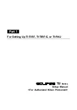
background image


Series


TI-TIRF Illuminator Unit 


TI-TIRF-E Motorized Illuminator Unit 


TI-PAU Photo Activation Illuminator Unit 

 TI-TIRF-PAU 

Illuminator 


LU4-B5 Beamsplitter 50/50 

Setup Manual 

<For Authorized Nikon Personnel> 
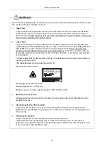


WARNING 


This manual is intended to provide setup instructions for Nikon 
representatives who have attended the lecture on laser safety and have been 
trained in setup operations. Attempts by others to set up the product may 
lead to accidents or equipment failure. NIKON is not responsible for personal 
injury or equipment damage resulting from equipment setup performed by 
unqualified persons. 

Be sure to observe the warnings and cautions described in this manual to 
ensure safety during setup.


*M456EN05*

M456 E

  10.9.NF.5 

Summary of Contents for Eclipse Ti Series

Page 1: ...uctions for Nikon representatives who have attended the lecture on laser safety and have been trained in setup operations Attempts by others to set up the product may lead to accidents or equipment failure NIKON is not responsible for personal injury or equipment damage resulting from equipment setup performed by unqualified persons Be sure to observe the warnings and cautions described in this ma...

Page 2: ......

Page 3: ...subject to change without notice This manual contains confidential information Do not disclose this manual to a third party other than the authorized Nikon personnel Although every effort has been made to ensure the accuracy of this manual errors or inconsistencies may remain If you note any points that are unclear or incorrect please contact a Nikon Service Department Some of the equipment descri...

Page 4: ...tup manual carefully and thoroughly before installing the product Safety instructions in this manual are marked with the following symbols to highlight their importance For your safety always follow the instructions marked with these symbols Symbol Description WARNING Disregarding instructions marked with this symbol may lead to serious injury or death CAUTION Disregarding instructions marked with...

Page 5: ...ely after it is turned off Do not touch the lamp and the lamphouse while the lamp is on and immediately after it is turned off to prevent the risk of burns Make sure that the lamp and the lamphouse are sufficiently cool before the lamp replacement Biohazard This symbol on the upper part of the microscope calls your attention on the following If a specimen is spilled onto the product it may cause t...

Page 6: ...ceding standards in accordance with local laws and regulations The laser safety officer LSO must take charge of this laser product and users should follow the instructions from the LSO FDA Class 3B Laser Product Laser Notice No 50 IEC Class 3B Laser Product LASER RADIATION AVOID EXPOSURE TO BEAM CLASS 3B LASER PRODUCT Wavelength 400 to 700 nm CW Beam divergence 0 01 to 2 91 rad Maximum power or en...

Page 7: ...wing conditions are not satisfied laser light may be irradiated from openings or reflected from reflective objects and unintended exposure of eyes and skin to laser light may result 1 A cap 3D STORM port a TV camera or a video camera is attached to each port 2 An objective or a cap is attached to each socket of the nosepiece 3 The optical fiber for laser light is securely fixed 4 The adapter for t...

Page 8: ... light source to be used and the manuals published by the lamp manufacturer if provided and follow their instructions 1 The mercury lamp or the xenon lamp radiates ultraviolet light that is harmful to the eyes and skin when the lamp is turned on Direct viewing of light from these lamps may result in blindness 2 Gas is sealed under very high pressure inside the lamps The pressure increases when the...

Page 9: ...cal alcohol for disinfecting the microscopy Never hold a flame near these solvents To use solvent read the instructions provided by the manufacturer and handle the solvent correctly and safely Note the following precautions to use a solvent with the product Keep solvent from the heat of the lamp the lamphouse and the power supply device Do not bring solvent near the product or its surroundings whe...

Page 10: ...not pull cables by the sheath instead firmly grasp the plug when connecting or disconnecting a cable 3 Emergency stop In an emergency turn off all power switches and unplug the power cords 4 Do not wet the product Do not wet nor spill a liquid on the product to avoid malfunction over heating or electric shock If a device is subject to contact with water immediately switch off the power switch to t...

Page 11: ...ct in hot or humid conditions may result in condensation or malfunction Make sure that the product is not subject to strong vibrations which may degrade image quality Consult with Nikon representatives about preventive measures you may take when the product is installed To prevent degradation malfunction or failure of the laser and the PC always use power supply that is free from electric noise or...

Page 12: ...nfiguration of This Manual This setup manual is made up of two parts Refer to the part which deals with the product you are setting up Part 1 For Setting Up TI TIRF TI TIRF E or TI PAU Part 2 For Setting Up TI TIRF PAU and LU4 B5 ...

Page 13: ...Part 1 For Setting Up TI TIRF TI TIRF E or TI PAU Series Setup Manual For Authorized Nikon Personnel ...

Page 14: ......

Page 15: ...cope Body with the TI PAU Photo Activation Illuminator Unit 1 26 1 3 4 C LU2 Two laser Unit 1 27 1 3 5 C LU3 Three laser Unit 1 28 1 3 6 C LU3EX Three laser Unit EX 1 29 1 3 7 LU4A Four laser Module A 1 30 1 3 8 LU LR Four laser PS Rack 1 31 1 3 9 TI LUSU Shutter Unit 1 32 1 3 10 TI LU4SU Shutter Unit LU4 1 34 1 3 11 TI TIRF TIRF Illuminator Unit 1 36 1 3 12 TI TIRF E Motorized TIRF Illuminator Un...

Page 16: ...U3EX Three laser Unit EX 1 122 5 3 1 Preparation 1 123 5 3 2 Laser Installation 1 125 5 3 3 Laser Rough Adjustment 1 1 128 5 3 4 Laser Rough Adjustment 2 1 139 5 3 5 Final Adjustment for the Ar Laser Light with the Optical Fiber 1 146 5 3 6 Final Adjustment for the He Ne Laser Light and 405 Laser Light with the Optical Fiber 1 152 5 3 7 Adjusting the AOM Controller When the AOM Unit Used Only 1 15...

Page 17: ...Checking Procedure 1 228 7 2 Check Sheet 1 229 8 Specifications and Performance 1 231 8 1 Overall Configuration 1 231 8 1 1 TIRF Illuminator Unit Motorized TIRF Illuminator Unit Configuration for Normal Microscopy Except N STORM 1 231 8 1 2 Motorized TIRF Illuminator Unit Configuration for N STORM 1 232 8 1 3 Photo Activation Illuminator Unit 1 234 8 1 4 Mountable lasers 1 235 8 1 5 TI LUSU Shutte...

Page 18: ...OPEN AVOID EXPOSURE TO THE BEAM Figure 1 1 1 For details see Section 8 1 Overall Configuration in Chapter 8 Specifications and Performance 1 Power supply devices for the laser devices 2 Laser unit C LU2 C LU3 C LU3EX 3 PC 4 Optical fiber 5 TI LUSU shutter unit 6 AC adapter for the shutter unit 7 TV camera video camera 8 TI FLC epi fl filter turret 9 Power supply device for the diascopic illuminati...

Page 19: ...TTE FROM OBJECTIVE APERT RS 232C LASER UNIT TI LUSU INPUT 1A POWER SAFETY COVER CLOSE BINO CLOSE 12V LASER SHUTTER Exclusive use for TI TIRF system Don t use this unit with other systems Figure 1 1 2 For details see Section 8 1 Overall Configuration in Chapter 8 Specifications and Performance 1 Power supply devices for the laser devices 2 Laser unit C LU2 C LU3 C LU3EX 3 PC 4 Optical fiber 5 TI LU...

Page 20: ... EXPOSURE TO THE BEAM Figure 1 1 3 For details see Section 8 1 Overall Configuration in Chapter 8 Specifications and Performance 1 Power supply devices for the laser devices 2 Laser unit LU4A 3 PC 4 Optical fiber 5 TI LU4SU shutter unit LU4 6 TV camera video camera 7 TI FLC epi fl filter turret 8 Power supply device for the diascopic illumination 9 TIRF illuminator unit 10 HG fiber light source 11...

Page 21: ...3B LASER RADIATION WHEN OPEN AVOID EXPOSURE TO THE BEAM SER RADIATIO OID EXPOSU CLASS 3B LASE AVOID EXPOSURE LASER LIGHT IS EMITTE FROM OBJECTIVE APERT Figure 1 1 4 For details see Section 8 1 Overall Configuration in Chapter 8 Specifications and Performance 1 Power supply devices for the laser devices 2 Laser unit LU4A 3 PC 4 Optical fiber 5 TI LU4SU shutter unit LU4 6 TV camera video camera 7 TI...

Page 22: ...WHEN OPEN AVOID EXPOSURE TO THE BEAM Figure 1 1 5 For details see Section 8 1 Overall Configuration in Chapter 8 Specifications and Performance 1 Power supply devices for the laser devices 2 Laser unit C LU2 C LU3 C LU3EX 3 PC 4 Optical fiber 5 TI LUSU shutter unit 6 AC adapter for the shutter unit 7 TV camera video camera 8 TI FLC E HQ motor epi fl filter turret 9 Power supply device for the dias...

Page 23: ...other systems CAUTION CLASS 3B LASER RADIATION WHEN OPEN AVOID EXPOSURE TO THE BEAM VORSICHT LASERSTRAHLUNG KLASSE 3B WENN ABDECKUNG GEÖFFNET NICHT DEM STRAHL AUSSETZEN CAUTION CLASS 3B LASER RADIATION WHEN OPEN AVOID EXPOSURE TO THE BEAM SER RADIATIO OID EXPOSU CLASS 3B LASE AVOID EXPOSURE LASER LIGHT IS EMITTE FROM OBJECTIVE APERT Figure 1 1 6 For details see Section 8 1 Overall Configuration in...

Page 24: ...ll Configuration in Chapter 8 Specifications and Performance 1 Power supply devices for the laser devices 2 Laser unit LU4A 3 PC 4 Optical fiber 5 TI LU4SU shutter unit LU4 6 TV camera video camera 7 TI FLC E HQ motor epi fl filter turret 8 Power supply device for the diascopic illumination 9 Hub controller A with AC adapter 10 Motorized TIRF illuminator unit 11 HG fiber light source 12 Remote con...

Page 25: ...WHEN OPEN AVOID EXPOSURE TO THE BEAM Figure 1 1 8 For details see Section 8 1 Overall Configuration in Chapter 8 Specifications and Performance 1 Power supply devices for the laser devices 2 Laser unit LU4A 3 PC 4 Optical fiber 5 TI LU4SU shutter unit LU4 6 TV camera video camera 7 TI FLC E HQ motor epi fl filter turret 8 Power supply device for the diascopic illumination 9 Hub controller A with A...

Page 26: ...Optical fiber 5 TI LU4SU shutter unit LU4 6 EM CCD camera 7 TI FLC E HQ motor epi fl filter turret 8 Power supply device for the diascopic illumination 9 Hub controller A with AC adapter 10 Motorized TIRF illuminator unit 11 HG fiber light source 12 Remote control pad 13 Laser safety cover 14 Interlock cable 15 USB cable 16 3D STORM port 17 DSC support columns 2 pieces 18 Ti E fixing plate 19 STOR...

Page 27: ...in Chapter 8 Specifications and Performance 1 Power supply devices for the laser devices 2 Laser unit LU4A 3 PC 4 Optical fiber 5 TI LU4SU shutter unit LU4 6 EM CCD camera 7 TI FLC E HQ motor epi fl filter turret 8 Power supply device for the diascopic illumination 9 Hub controller A with AC adapter 10 Motorized TIRF illuminator unit 11 HG fiber light source 12 Remote control pad 13 Laser safety c...

Page 28: ...LASS 3B LASER RADIATION WHEN OPEN AVOID EXPOSURE TO THE BEAM Figure 1 1 11 For details see Section 8 1 Overall Configuration in Chapter 8 Specifications and Performance 1 Power supply devices for the laser devices 2 Laser unit C LU2 C LU3 C LU3EX 3 PC 4 Optical fiber 5 TI LUSU shutter unit 6 AC adapter for the shutter unit 7 TV camera video camera 8 TI FLC epi fl filter turret 9 Power supply devic...

Page 29: ...AUSSETZEN CAUTION CLASS 3B LASER RADIATION WHEN OPEN AVOID EXPOSURE TO THE BEAM RS 232C LASER UNIT TI LUSU INPUT 1A POWER SAFETY COVER CLOSE BINO CLOSE 12V LASER SHUTTER Exclusive use for TI TIRF system Don t use this unit with other systems Figure 1 1 12 For details see Section 8 1 Overall Configuration in Chapter 8 Specifications and Performance 1 Power supply devices for the laser devices 2 Las...

Page 30: ...OPEN AVOID EXPOSURE TO THE BEAM Figure 1 1 13 For details see Section 8 1 Overall Configuration in Chapter 8 Specifications and Performance 1 Power supply devices for the laser devices 2 Laser unit LU4A 3 PC 4 Optical fiber 5 TI LU4SU shutter unit LU4 6 TV camera video camera 7 TI FLC epi fl filter turret 8 Power supply device for the diascopic illumination 9 Photo activation illuminator unit 10 H...

Page 31: ...POSURE TO THE BEAM VORSICHT LASERSTRAHLUNG KLASSE 3B WENN ABDECKUNG GEÖFFNET NICHT DEM STRAHL AUSSETZEN CAUTION CLASS 3B LASER RADIATION WHEN OPEN AVOID EXPOSURE TO THE BEAM Figure 1 1 14 For details see Section 8 1 Overall Configuration in Chapter 8 Specifications and Performance 1 Power supply devices for the laser devices 2 Laser unit LU4A 3 PC 4 Optical fiber 5 TI LU4SU shutter unit LU4 6 TV c...

Page 32: ...2 1 ND filters ND2 and ND4 1 Installed only when the N STORM kit is mounted Table 1 2 1 Laser mounting position Model name L1 L2 L3 L4 C LU2 two laser unit 405 nm to 514 nm 532 nm to 640 nm C LU3 three laser unit 405 nm to 445 nm 594 nm to 645 nm 488 nm to 514 nm 532 nm to 561 nm 633 nm C LU3EX three laser unit EX 405 nm to 445 nm 594 nm to 645 nm 488 nm to 514 nm 532 nm to 561 nm 633 nm LU4A four...

Page 33: ... 3B LASER RADIATIO N WHEN OPEN AVOID EXPOSU RE TO THE BEAM VORSICH T LASERST RAHLUNG KLASSE 3B WENN ABDECKU NG GEÖFFNE T NICHT DEM STRAHL AUSSETZ EN CAUTION CLASS 3B LASER RADIATIO N WHEN OPEN AVOID EXPOSU RE TO THE BEAM VORSICH T LASERST RAHLUNG KLASSE 3B WENN ABDECKU NG GEÖFFNE T NICHT DEM STRAHL AUSSETZ EN CAUTION CLASS 3B LASER RADIATIO N WHEN OPEN AVOID EXPOSU RE TO THE BEAM VORSICH T LASERST...

Page 34: ...S N D 16 N D 8 N D 2 Coarse Fine ExFine Obj ON O FF 6V30W MAX 12V100 W CAUTION CLASS 3B LASER RADIATIO N WHEN OPEN AVOID EXPOSU RE TO THE BEAM VORSICH T LASERST RAHLUNG KLASSE 3B WENN ABDECKU NG GEÖFFNE T NICHT DEM STRAHL AUSSETZ EN CAUTION CLASS 3B LASER RADIATIO N WHEN OPEN AVOID EXPOSU RE TO THE BEAM VORSICH T LASERST RAHLUNG KLASSE 3B WENN ABDECKU NG GEÖFFN ET NICHT DEM STRAHL AUSSETZ EN CAUTI...

Page 35: ...SE 3B WENN ABDECKU NG GEÖFFNE T NICHT DEM STRAHL AUSSETZE N CAUTION CLASS 3B LASER RADIATION WHEN OPEN AVOID EXPOSUR E TO THE BEAM VORSICHT LASERSTR AHLUNG KLASSE 3B WENN ABDECKU NG GEÖFFNE T NICHT DEM STRAHL AUSSETZE N AVOID EXPOS URE LASER LIGHT IS EMITTE D FROM THIS APERTU RE LASER RADIAT ION AVOID EXPOS URE TO BEAM CLASS 3B LASER PRODU CT AVOID EXPOS URE LASER LIGHT IS EMITTED FROM OBJECT IVE ...

Page 36: ...tivation illuminator unit and Ti U system ON OFF 6V30W MAX 12V100 W N D 2 N D 8 N D 16 LASE R RADIA TION AVOID EXPO SURE TO BEAM CLAS S 3B LASE R PROD UCT AVOID EXPO SURE LASER LIGHT IS EMITTE D FROM OBJEC TIVE APERT URE CAUTION CLASS 3B LASER RADIATIO N WHEN OPEN AVOID EXPOSU RE TO THE BEAM VORSICH T LASERST RAHLUN G KLASSE 3B WENN ABDECK UNG GEÖFFN ET NICHT DEM STRAHL AUSSETZ EN CAUTION CLASS 3B...

Page 37: ...e received including interference that may cause undesired operation Cet appareil numérique de la classe A est confirme à la norme NMB 003 du Canada This Class A digital apparatus complies with Canadian ICES 003 MADE IN JAPAN 5 IEC caution label Class 3B area 6 IEC caution label Class 3B area 7 IEC caution label Class 3B area CAUTION CLASS 3B LASER RADIATION WHEN OPEN AVOID EXPOSURE TO THE BEAM VO...

Page 38: ... label 1 9 IEC aperture label 2 AVOID EXPOSURE LASER LIGHT IS EMITTED FROM OBJECTIVE APERTURE AVOID EXPOSURE LASER LIGHT IS EMITTED FROM THIS APERTURE LA SE R RA DIA TIO N AV OID EX PO SU RE TO BE AM CL AS S 3B LA SE R PR OD UC T AV OID EX PO SU RE LAS ER LIG HT I S EM I T TED FRO M OB JEC TIV E APE RTU RE CAUTION CLASS 3B LASER RADIATION WHEN OPEN AVOID EXPOSURE TO THE BEAM VORSICHT LASERSTRA HLU...

Page 39: ...SER LIGHT IS EMITTED FROM OBJECTIVE APERTURE AVOID EXPOSURE LASER LIGHT IS EMITTED FROM THIS APERTURE LA SE R RA DIA TIO N AV OID EX PO SU RE TO BE AM CL AS S 3B LA SE R PR OD UC T AV OID EX PO SU RE LAS ER LIG HT I S EM I T TED FRO M OBJ ECT I V E APE RTU RE CAUTION CLASS 3B LASER RADIATION WHEN OPEN AVOID EXPOSURE TO THE BEAM VORSICHT LASERSTRA HLUNG KLASSE 3B WENN ABDECKUNG GEÖFFNET NICHT DEM S...

Page 40: ...RE ON OFF 6V30W MAX 12V100W LA SE R RA DIA TIO N AV OID EX PO SU RE TO BE AM CL AS S 3B LA SE R PR OD UC T AV OID EX PO SU RE LAS ER LIG HT I S EM I T TED FRO M OB JEC TIV E APE RTU RE CAUTION CLASS 3B LASER RADIATION WHEN OPEN AVOID EXPOSURE TO THE BEAM VORSICHT LASERSTRA HLUNG KLASSE 3B WENN ABDECKUN G GEÖFFNET NICHT DEM STRAHL AUSSETZEN LA SE R RA DIA TIO N AV OID EX PO SU RE TO BE AM CL AS S 3...

Page 41: ...aser Unit Make sure that the labels are affixed in place 1 IEC warning label laser hazard symbol 6 IEC caution label Class 3B area CAUTION CLASS 3B LASER RADIATION WHEN OPEN AVOID EXPOSURE TO THE BEAM VORSICHT LASERSTRAHLUNG KLASSE 3B WENN ABDECKUNG GEÖFFNET NICHT DEM STRAHL AUSSETZEN Figure 1 3 4 6 1 ...

Page 42: ...laser Unit Make sure that the labels are affixed in place 1 IEC warning label laser hazard symbol 6 IEC caution label Class 3B area CAUTION CLASS 3B LASER RADIATION WHEN OPEN AVOID EXPOSURE TO THE BEAM VORSICHT LASERSTRAHLUNG KLASSE 3B WENN ABDECKUNG GEÖFFNET NICHT DEM STRAHL AUSSETZEN Figure 1 3 5 6 1 ...

Page 43: ...aser Unit EX Make sure that the labels are affixed in place 1 IEC warning label laser hazard symbol 6 IEC caution label Class 3B area CAUTION CLASS 3B LASER RADIATION WHEN OPEN AVOID EXPOSURE TO THE BEAM VORSICHT LASERSTRAHLUNG KLASSE 3B WENN ABDECKUNG GEÖFFNET NICHT DEM STRAHL AUSSETZEN Figure 1 3 6 6 1 ...

Page 44: ...bels and Openings 1 30 1 3 7 LU4A Four laser Module A Make sure that the labels are affixed in place 1 IEC warning label laser hazard symbol 12 IEC caution label Class 4 area Figure 1 3 7 For the laser path inside the laser unit see Section 1 2 1 Laser Unit 12 1 ...

Page 45: ...er 1 System Configurations and Part Names 1 3 Safety Labels and Openings 1 31 1 3 8 LU LR Four laser PS Rack Make sure that the label is affixed in place 11 Caution label Front view Rear view Figure 1 3 8 11 ...

Page 46: ...es with Canadian ICES 003 MADE IN JAPAN Exclusive use for TI TIRF system Don t use this unit with other systems RS 232C LASER UNIT TI LUSU INPUT 1A POWER SAFETY COVER CLOSE BINO CLOSE 12V LASER SHUTTER T h i s d e v i c e c o m p l i e s w i t h P a r t 1 5 o f t h e F C C R u l e s O p e r a t i o n i s s u b j e c t t o t h e f o l l o w i n g t w o c o n d i t i o n s 1 t h i s d e v i c e m a ...

Page 47: ...IN JAPAN Exclusive use for TI PAU system Don t use this unit with other systems RS 232C LASER UNIT TI LUSU INPUT 1A POWER SAFETY COVER CLOSE BINO CLOSE 12V LASER SHUTTER ON OFF T h i s d e v i c e c o m p l i e s w i t h P a r t 1 5 o f t h e F C C R u l e s O p e r a t i o n i s s u b j e c t t o t h e f o l l o w i n g t w o c o n d i t i o n s 1 t h i s d e v i c e m a y n o t c a u s e h a r m...

Page 48: ...de la classe A est confirme à la norme NMB 003 du Canada This Class A digital apparatus complies with Canadian ICES 003 MADE IN JAPAN POWER TI LU4SU EMISSION LASER T h i s d ev i c e c o m p l i e s w i t h Pa r t 1 5 o f t h e F C C Ru l e s O p e ra t i o n i s s ub j e c t t o t h e fol l ow ing t wo c o n d i t i o n s 1 t h i s d ev i c e m ay n o t c au s e h a r m fu l i n t e r fer e n c e...

Page 49: ... la norme NMB 003 du Canada This Class A digital apparatus complies with Canadian ICES 003 MADE IN JAPAN POWER TI LU4SU EMISSION LASER This dev i c e c o m p l i e s w i t h Pa r t 1 5 o f t h e F C C Ru l e s O p e ra t i o n i s s ub j e c t t o t h e fol l ow ing t wo c o n d i t i o n s 1 t h i s d ev i c e m ay n o t c au s e h a r m fu l i n t e r fer e n c e a n d 2 t h i s d ev i c e mu s ...

Page 50: ...HT LASERSTRAHLUNG KLASSE 3B WENN ABDECKUNG GEÖFFNET NICHT DEM STRAHL AUSSETZEN A S ND4 FILTER ND8 N D 4 N D 8 N D 16 N D 8 N D 2 CA UT I O N CL AS S 3B LA SE R RA DI AT I O N W HE N OP EN AV OI D EX PO SU RE TO TH E BE AM VO RS I C HT LA SE RS TR AH LU NG KL AS SE 3B W EN N AB DE CK UN G GE ÖF FN ET NI CH T DE M ST RA HL AU SS ET ZE N CA UT I O N CL AS S 3B LA SE R RA DI AT I O N W HE N OP EN AV O...

Page 51: ...bels are affixed near each of the openings 3 Model name and serial number label 5 IEC caution label Class 3B area 7 IEC caution label Class 3B area CAUTION CLASS 3B LASER RADIATION WHEN OPEN AVOID EXPOSURE TO THE BEAM VORSICHT LASERSTRAHLUNG KLASSE 3B WENN ABDECKUNG GEÖFFNET NICHT DEM STRAHL AUSSETZEN CAUTION CLASS 3B LASER RADIATION WHEN OPEN AVOID EXPOSURE TO THE BEAM VORSICHT LASERSTRAHLUNG KLA...

Page 52: ...e affixed near each of the openings 3 Model name and serial number label 5 IEC caution label Class 3B area 7 IEC caution label Class 3B area CAUTION CLASS 3B LASER RADIATION WHEN OPEN AVOID EXPOSURE TO THE BEAM VORSICHT LASERSTRAHLUNG KLASSE 3B WENN ABDECKUNG GEÖFFNET NICHT DEM STRAHL AUSSETZEN CAUTION CLASS 3B LASER RADIATION WHEN OPEN AVOID EXPOSURE TO THE BEAM VORSICHT LASERSTRAHLUNG KLASSE 3B ...

Page 53: ...LASERSTRAHLUNG KLASSE 3B WENN ABDECKUNG GEÖFFNET NICHT DEM STRAHL AUSSETZEN I N ND 2 I N A S ND4 FILTER ND8 N D 4 N D 8 N D 2 N D 8 N D 16 CAUTION CLASS 3B LASER RADIATION WHEN OPEN AVOID EXPOSURE TO THE BEAM CA UT I O N CL AS S 3B LA SE R RA DI AT I O N W HE N OP EN AV OI D EX PO SU RE TO TH E BE AM VO RS I C HT LA SE RS TR AH LU NG KL AS SE 3B W EN N AB DE CK UN G GE ÖF FN ET NI CH T DE M ST RA ...

Page 54: ...OSURE TO THE BEAM VORSICHT LASERSTRAHLUNG KLASSE 3B WENN ABDECKUNG GEÖFFNET NICHT DEM STRAHL AUSSETZEN CAUTION CLASS 3B LASER RADIATION WHEN OPEN AVOID EXPOSURE TO THE BEAM SER RADIATIO OID EXPOSU CLASS 3B LASE AVOID EXPOSURE LASER LIGHT IS EMITTE FROM OBJECTIVE APERT Figure 1 4 2 TIRF illuminator unit Laser safety cover Optical path selector knob To laser unit To PC TI FLC epi fl filter turret Fi...

Page 55: ...ment 3 Laser position adjustment knob for forward and backward adjustment 4 ND filter sliders 5 Mirror switching lever Push in TIRF 60 and Epi 40 Pull out TIRF 100 6 Focal point adjustment knob 7 Condenser lens locking screw Parts used in the epi fl microscopy operation 8 Field diaphragm centering screws 9 Field diaphragm open close lever 10 Aperture diaphragm centering screws 11 Aperture diaphrag...

Page 56: ... or gotten wet misoperation may occur Laser safety kit LAS ER RAD I A TION AVO I D EXP OSU RE TO BEA M CLA SS 3B LAS ER PRO DUC T AVO I D EXP OSU RE LASE R LIGH T I S EMIT TED FROM OBJE CTIV E APER TURE CAUTION CLASS 3B LASER RADIATION WHEN OPEN AVOID EXPOSURE TO THE BEAM VORSICHT LASERSTRAHLUNG KLASSE 3B WENN ABDECKUNG GEÖFFNET NICHT DEM STRAHL AUSSETZEN AVOID EXPOSURE LASER LIGHT IS EMITTED FROM...

Page 57: ...gure 1 4 9 The shutter unit controls motorized shutters in the laser unit Use this unit in combination with the LU4A laser unit If the safety interlock functions all the shutters are closed and the lamp turns off To unlock the safety interlock solve what caused the safety interlock being locked then cancel the safety interlock from the software Safety cover signal connector AC adapter connector Ey...

Page 58: ...ion left port 20 80 Observation right port 20 80 L Left port 100 Ti U B EYE Observation port 100 R Right port 100 B Bottom port 100 L Left port 100 The Ti U is also available with an optical path splitter prism preinstalled at the auxiliary port The light intensity ratio of visual observation to left port is 20 to 80 In this case set the optical path selector knob as follows EYE Observation port 1...

Page 59: ...ID EXPOSURE LASER LIGHT IS EMITTE FROM OBJECTIVE APERT Figure 1 4 11 When used with four laser module A POWER TI LU4SU EMISSION LASER CAUTION CLASS 3B LASER RADIATION WHEN OPEN AVOID EXPOSURE TO THE BEAM CAUTION CLASS 3B LASER RADIATION WHEN OPEN AVOID EXPOSURE TO THE BEAM Figure 1 4 12 Laser safety cover To laser unit To PC TI LUSU shutter unit Filter cube port cover retaining plate part of laser...

Page 60: ...gm open close lever 8 Aperture diaphragm centering screws 9 Aperture diaphragm open close lever 10 ND filter sliders 11 Excitation filter slider 12 Connector for the HG fiber light source adapter The TI RCP remote control pad or TI ERGC ergo controller allows users to change illumination to TIRF or episcopic as well as adjust the laser right or left TIRF illumination angle adjustment TI RCP remote...

Page 61: ...d or gotten wet misoperation may occur Laser safety kit LAS ER RAD I A TION AVO I D EXP OSU RE TO BEA M CLA SS 3B LAS ER PRO DUC T AVO I D EXP OSU RE LASE R LIGH T I S EMIT TED FROM OBJE CTIV E APER TURE CAUTION CLASS 3B LASER RADIATION WHEN OPEN AVOID EXPOSURE TO THE BEAM VORSICHT LASERSTRAHLUNG KLASSE 3B WENN ABDECKUNG GEÖFFNET NICHT DEM STRAHL AUSSETZEN AVOID EXPOSURE LASER LIGHT IS EMITTED FRO...

Page 62: ... LU4 POWER TI LU4SU EMISSION LASER Figure 1 4 20 The shutter unit controls motorized shutters in the laser unit Use this unit in combination with the LU4A laser unit If the safety interlock functions all the shutters are closed and the lamp turns off To unlock the safety interlock solve what caused the safety interlock being locked then cancel the safety interlock from the software Safety cover si...

Page 63: ...POSURE TO THE BEAM CAUTION CLASS 3B LASER RADIATION WHEN OPEN AVOID EXPOSURE TO THE BEAM Figure 1 4 22 Optical path selector switch Ti E EYE Observation port 100 L100 Left port 100 L80 Left port 80 and observation port 20 R100 Right port 100 Ti E B EYE Observation port 100 L100 Left port 100 L80 Left port 80 and observation port 20 B100 Bottom port 100 Motorized TIRF illuminator unit Filter cube c...

Page 64: ...ield diaphragm open close lever 9 Aperture diaphragm centering screws 10 Aperture diaphragm open close lever 11 ND filter sliders 12 Excitation filter slider 13 Connector for the HG fiber light source adapter The TI RCP remote control pad or TI ERGC ergo controller allows users to change the illumination to TIRF or episcopic as well as adjust the laser right or left TIRF illumination angle adjustm...

Page 65: ...0 EYE DISP LAY MEM ORY PFS ON REC ALL Z RE SET BRI GHT NES S R10 0 L10 0 FOC US Figure 1 4 25 The cover prevents laser light from leaking If the laser safety cover is not attached the motorized shutters of the laser unit do not open Figure 1 4 26 If the safety interlock part is touched or gotten wet misoperation may occur Figure 1 4 27 When using piezo stages To use the piezo stage together the TI...

Page 66: ...lider cover protection plate filter cube port cover retraining plate and safety labels Before using the product check that the part shown in the left figure is attached For the types and positions of safety labels see Section 1 3 2 Ti E Microscope Body TI FLC E motorized epi fl filter turret or TI FLC E HQ motor epi fl filter turret Figure 1 4 29 The epi fl filter turret is used to select an excit...

Page 67: ...croscope and EM CCD camera when performing the N STORM microscopy is equipped with the cylindrical lens that is placed in or out of the optical imaging system to the camera by sliding the handle In normal microscopy and 2D STORM microscopy remove the cylindrical lens out of the optical path and in capturing the 3D STORM image insert it in the optical path If the cylindrical lens is installed durin...

Page 68: ...ASER RADIATION WHEN OPEN AVOID EXPOSURE TO THE BEAM Figure 1 4 33 When used with four laser module A CAUTION CLASS 3B LASER RADIATION WHEN OPEN AVOID EXPOSURE TO THE BEAM Figure 1 4 34 TI FLC epi fl filter turret Specimen cover Photo activation illuminator unit TI LUSU shutter unit Interlock cable Photo activation illuminator unit TI LU4SU shutter unit LU4 TI FLC epi fl filter turret Interlock cab...

Page 69: ...I D EXP OSU RE TO BEA M CLA SS 3B LAS ER PRO DUC T AVO I D EXP OSU RE LASE R LIGH T I S EMIT TED FROM OBJE CTIV E APER TURE CAUTION CLASS 3B LASER RADIATION WHEN OPEN AVOID EXPOSURE TO THE BEAM VORSICHT LASERSTRAHLUNG KLASSE 3B WENN ABDECKUNG GEÖFFNET NICHT DEM STRAHL AUSSETZEN AVOID EXPOSURE LASER LIGHT IS EMITTED FROM THIS APERTURE CAUTION CLASS 3B LASER RADIATION WHEN OPEN AVOID EXPOSURE TO THE...

Page 70: ...M VORSICHT LASERSTRAHLUNG KLASSE 3B WENN ABDECKUNG GEÖFFNET NICHT DEM STRAHL AUSSETZEN Figure 1 4 37 The laser safety kit is composed of the filter slider cover protection plate for nosepiece filter cube port cover retaining plate and safety labels 9 IEC aperture label 2 and 7 IEC caution label Class 3B areas Before using the microscope CHECK that each part of the laser safety kit is correctly att...

Page 71: ...scope body PORT Figure 1 4 41 The laser shutter does not open when the binocular route of the optical path EYE is selected The Ti U is also available with an optical path splitter prism preinstalled at the auxiliary port The light intensity ratio of visual observation to left port is 20 to 80 In this case set the optical path selector knob as follows Safety cover signal connector AC adapter connec...

Page 72: ... lasers for each position of laser units see Section 8 1 4 Mountable Lasers in Chapter 8 Specifications and Performance Three laser unit C LU3 Figure 1 4 43 1 Laser mounting position L1 2 Laser mounting position L2 3 Laser mounting position L3 4 Shutter unit connector 5 ND filter slider 6 Single mode fiber For details of available lasers for each position of laser units see Section 8 1 4 Mountable...

Page 73: ...Laser mounting position L2 3 Laser mounting position L3 4 Shutter unit connector 5 Single mode fiber 6 Brightness control knob 7 Ar wavelength selector optional 8 AOM connector optional For details of available lasers for each position of laser units see Section 8 1 4 Mountable Lasers in Chapter 8 Specifications and Performance 3 6 1 2 5 6 6 7 8 4 ...

Page 74: ...not use in this system 12 Interlock cable connectors 13 LUSU connector 14 USB connector 15 LD connector Do not use in this system 1 Installed only when the N STORM kit is mounted Precautions when handling the laser unit The laser head and the optical fiber are precisely aligned in these units Avoid subjecting the laser head or optical fiber to vibration or shock Contact the distributor if you need...

Page 75: ...ION laser indicator 2 POWER laser indicator 3 EMISSION key switch 4 Power switch 5 INTERLOCK connector 6 Cooling fan 7 Power breaker for 15 A line 8 Power breaker for 5 A line 9 Caution label 10 Name plate for 15 A line ratings 11 Name plate for 5 A line ratings 12 AC inlet for 15 A line 13 AC inlet for 5 A line 5 11 6 7 13 1 2 3 4 9 10 12 8 ...

Page 76: ...VORSICHT LASERSTRAHLUN G KLASSE 3B WENN ABDECKUNG GEÖFFNET NICHT DEM STRAHL AUSSETZEN ON OFF 6V30W MAX 12V100W Figure 1 4 49 9 IEC aperture label 2 AVOID EXPOSURE LASER LIGHT IS EMITTED FROM THIS APERTURE Figure 1 4 50 Filter slider cover The filter slider cover is a component designed for preventing unintended exposure of eyes or skin at the slider port to laser light emitted to the dia pillar il...

Page 77: ...t to avoid accidental jamming of fingers inserted into the gap or the laser radiation from the gap Two types of protection plate are prepared for the nosepiece being used One for the TI N6 TI ND6 and TI ND6 E nosepieces is supplied with Ti E and Ti E B and the other for the TI ND6 PFS nosepiece is supplied with the nosepiece Follow the procedure described in 4 2 3 Attaching the Laser Safety Kit to...

Page 78: ...t and perform focus adjustment and centering Important The dichroic mirror inside the filter cube is used to split the optical path therefore the dichroic mirror with a poor flatness may cause lens effect due to a curved surface reflection resulting in poor image formation Use a dichroic mirror with higher flatness to be used for optical path split Figure 1 4 51 C mount adapter clamp screws two se...

Page 79: ... the TIRF illuminator unit motorized TIRF illuminator unit photo activation illuminator unit is attached to the lower tier When attaching to the lower tier embed the TI TIRF stage up lens into the TIRF illuminator unit motorized TIRF illuminator unit photo activation illuminator unit to correct the condensing position and provide the optimum illumination performance Contact your own Nikon represen...

Page 80: ...I BSUK70 70 mm stage up kit Figure 1 4 53 Positioning pin Stage support block Nosepiece support block Epi fl filter turret support block left Shielding plate Epi fl filter turret support block right Dia illuminator pillar support block Positioning pin Support pillar extension ...

Page 81: ... for the four laser module 100 VAC area 125 VAC 7 A or higher 200 VAC area 250 VAC 6 A or higher one cable for the AOM controller 100 VAC area 125 VAC 7 A or higher 200 VAC area 250 VAC 6 A or higher two cables for the laser PS rack 100 VAC area 125 VAC 7 A or higher 200 VAC area 250 VAC 6 A or higher and 100 VAC area 125 VAC 15 A or higher 200 VAC area 250 VAC 10 A or higher CAUTION Be sure to pr...

Page 82: ...tection goggles Calibrated power meter Figure 2 1 1 Figure 2 1 2 Power measurement attachment Dichroic mirror centering tool Figure 2 1 3 Figure 2 1 4 Coupler centering tool Centering tool for visual observations and mirror for observing centering tool Figure 2 1 5 Figure 2 1 6 Nikon 2 piece M4 screwdriver set with red handles Polarization orientation adjustment tool and polarizer equipped tool Fi...

Page 83: ...F E Mounting the filter cubes Attaching the camera 3 For two laser unit and three laser unit For three laser unit EX For the four laser module A For the four laser PS rack 4 Connection to the Shutter Unit Connection to the fiber light source TI TIRF TI TIRF E or TI PAU Replacing the optical path switch mirror if necessary 5 Laser safety check Check sheet entry Setting Up the PC and Operation Softw...

Page 84: ... microscopy images are observed on a monitor via a camera attached to the microscope camera port TIRF images and laser port images from PAU microscopy cannot be observed through the eyepieces Make sure to set up the PC and operation software for the camera to be used ...

Page 85: ...mination TI FLC E HQ Three exclusive high precision filter cubes are supplied with the TI FLC E HQ as accessories Fiber optic light source Episcopic light source Lamphouse power supply Make sure to read the instruction manuals for the product 26 Stage ring 32 32 is made of glass Stage up kit TI BSUK70 Microscope and accessories Back port unit TI BPU TI BSUK70 70 mm stage up kit is required TI TIRF...

Page 86: ...TV camera Commercially available TV camera An adapter is required for connection to the microscope port Two laser unit C LU2 Three laser unit C LU3 Three laser unit EX C LU3EX Laser Unit Four laser module A LU4A See Chapter 5 Laser Unit for details on which lasers can be mounted Filter slider cover Filter cube port cover retaining plate Safety label Ti laser safety kit Protection plate ...

Page 87: ...age up kit TI BSUK70 Microscope and accessories Back port unit TI BPU TI BSUK70 70 mm stage up kit is required Photo activation illuminator unit TI PAU Switches PA GFP EPI Requires an optical path switch mirror Photo activation illuminator unit Fiber C1 single mode fiber PC Commercially available PC Monitor Commercially available monitor PA GFP image observation TV camera Commercially available TV...

Page 88: ... photo activation illuminator unit Page 1 75 2 Attach the dichroic mirrors photo activation illuminator unit only Page 1 77 3 Attach the field diaphragm unit Page 1 78 4 Attach the epi fl filter turret Page 1 79 5 Assemble the remaining microscope parts Page 1 79 6 Attach the laser safety cover TIRF illuminator unit or motorized TIRF illuminator unit only Page 1 80 7 Attach the light shielding pla...

Page 89: ... Insert the light source into the guide on the back of the microscope main body Figure 4 2 2 2 Secure the light source by tightening the 4 clamp screws using the Allen wrench Figure 4 2 3 3 Attach the support pillar to the light source 1 Use an Allen wrench to loosen the clamp screw securing the support pillar so that the sliding part at the end slides freely 2 Screw the support pillar into the mo...

Page 90: ...on port TI TIRF Figure 4 2 6 6 Remove the anchor on the laser side The laser position adjusting mechanism comes equipped with an anchor for transportation Be sure to remove the anchor before turning the laser position adjustment knobs Attempting to turn either of the knobs without first removing the anchor may cause the mechanism to malfunction 1 For TI PAU The two laser position adjustment knobs ...

Page 91: ...on inside the photo activation illuminator unit Since the attachment does not ship with a mirror attached you must attach one following the procedure below You can also change the light intensity ratio of laser light and episcopic illumination by switching the dichroic mirror and operating the optical path switch lever Ordinarily you should attach a total reflection mirror When using a total refle...

Page 92: ...ing hole on the mirror unit Securely attach the mirror unit to the illuminator to fit the pin on the main body 2 Screw the cap of the mirror replacement opening until it is closed 3 Tighten the optical path switching module screw using the Allen wrench and secure the cover 3 Attach the field diaphragm unit CAUTION CLASS 3B LASER RADIATION WHEN OPEN AVOID EXPOSURE TO THE BEAM VORSICHT LASERSTRA HLU...

Page 93: ...ed after the filter cube port cover is removed Figure 4 2 11 When using the epi fl filter turret in combination with the Ti E or Ti E B the protection plate for nosepiece must be installed between the epi fl filter turret and the nosepiece For installation procedure see Section 4 2 3 Attaching the Laser Safety Kit 5 Assemble the remaining microscope parts Refer to the instruction manual included w...

Page 94: ...AX 12V100W Figure 4 2 12 If you are using the TIRF illuminator unit or the motorized TIRF illuminator unit the motorized shutter will not open unless the laser safety cover is attached on the stage Make sure it is attached in the prescribed position 1 Place the laser safety cover body on the stage and secure it by tightening the 4 screws with the Allen wrench 2 Connect the laser safety cover s cab...

Page 95: ...freely on spaces in which no filter cube is inserted 3 Re attach the filter cube port cover Note Excitation and barrier filters can be removed from the filter cube and replaced with other filters The filters are screwed into the filter cube 4 Attach the filter cube port cover retaining plate Important Three exclusive high precision filter cubes are supplied with the TI FLC E HQ motorized epi fl fi...

Page 96: ... the dia pillar illuminator 100W LA SE R RA DIA TIO N AV OID EX PO SU RE TO BE AM CL AS S 3B LA SE R PR OD UC T AV OID EX PO SU RE LAS ER LIG HT I S EM I T TED FRO M OB JEC TIV E APE RTU RE CAUTION CLASS 3B LASER RADIATION WHEN OPEN AVOID EXPOSURE TO THE BEAM VORSICHT LASERSTRA HLUNG KLASSE 3B WENN ABDECKUNG GEÖFFNET NICHT DEM STRAHL AUSSETZEN AVOID EXPOSURE LASER LIGHT IS EMITTED FROM THIS APERTU...

Page 97: ...LASER PRODUCT AVOID EXPOSURE LASER LIGHT IS EMITTED FROM OBJECTIVE APERTURE Figure 4 2 17 Top surface of stage photo activation illuminator unit Make sure that the following three warning labels at the rear left when viewed from the Binocular eyepiece tube 1 IEC warning label laser hazard symbol 2 IEC explanatory label Class 3B laser product and 8 IEC aperture label 1 is affixed LASER RADIATION AV...

Page 98: ...ing Up the Microscope 4 2 Setup Procedure 1 84 Laser unit Remove the laser safety label if it is attached to the laser unit Figure 4 2 19 About 30 mm About 12 mm Remove the laser safety labels About 20 mm About 12 mm ...

Page 99: ...microscope to the anti vibration table according to the inch holes or centimeter holes 3D STORM port Attach an optical system for N STORM to the microscope 3D STORM port Combination of A1 and 3D STORM port Figure 4 2 21 Detach the plastic cover on the side port of the microscope and install the 3D STORM port When using the port independently install it in the left side port When using the port tog...

Page 100: ...er introduction section in the motorized TIRF illuminator unit You can see a slot to insert the STORM slider Insert the slider into the slot Then attach the cover to prevent the slider from coming off Insert this slider during N STORM microscopy but slide it out of the optical path in other cases Lambda plate slider Insert an optical device for polarization adjustment to perform N STORM microscopy...

Page 101: ...ther for the TI ND6 PFS nosepiece is supplied with the nosepiece Follow the procedure below to attach each protection plate If the Perfect Focus System is not used CAUTION CLASS 3B LASER RADIATION WHEN OPEN AVOID EXPOSURE TO THE BEAM VORSICHT LASERSTRA HLUNG KLASSE 3B WENN ABDECKUNG GEÖFFNET NICHT DEM STRAHL AUSSETZEN AVOID EXPOSURE LASER LIGHT IS EMITTED FROM THIS APERTUR E N AM G ET N Figure 4 2...

Page 102: ...ved in step 1 3 With the cable of the PFS6 nosepiece being routed through the cable port of the protection plate to the Ti E or Ti E B attach the PFS6 nosepiece to the Ti E or Ti E B and secure it using the 4 mm hexagonal screwdriver appended to the Ti E and Ti E B Figure 4 2 28 3 Attach the filter cube port cover retaining plate 3 1 After attaching the filter cube re attach the filter cube port c...

Page 103: ...he top of the epi fl filter turret support blocks Use the 2 mm hexagonal screwdriver supplied with the microscope to secure it by tightening four hexagon socket head button bolts 4 Attach the nosepiece support block on the installation surface of the nosepiece on the microscope Use the 4 mm hexagonal screwdriver supplied with the microscope to secure it by tightening two hexagon socket head bolts ...

Page 104: ... Hexagon socket head button bolt M3 four Epi fl filter turret support block left Hexagon socket head bolt M3 two Hexagon socket head bolt M5 two Shielding plate Hexagon socket head bolt M5 four Dia illuminator pillar support block Nosepiece support block Epi fl filter turret support block right Hexagon socket head bolt M3 two ...

Page 105: ...unit motorized TIRF illuminator unit photo activation illuminator unit to the upper tier attach the support pillar extension supplied with the stage up kit to the support pillar supplied with the illuminator unit Figure 4 2 30 Support pillar extension supplied with the stage up kit Support pillar supplied with the illuminator unit ...

Page 106: ...4 mm to secure it from behind by tightening screws The following figure shows the back port unit being attached to the lower tier To attach the unit to the upper tier attach a unit to be attached to the lower tier first and then attach the one to the upper tier You must have installed the HUB controller when you use a HUB controller Attach the camera at the end Figure 4 2 31 Insert the back port u...

Page 107: ... are turned on Use the lowest output power rating during setup For Ar lasers use standby mode during setup The laser units are heavy Without the lasers installed the two laser unit weighs approximately 13 kg the three laser unit weighs approximately 27 kg and the three laser unit EX weighs approximately 24 kg the four laser module A weighs approximately 43 kg Do not attempt to lift laser units una...

Page 108: ...nd the illuminator unit One two laser unit two three laser units and one four laser module are available Use any laser unit with an optical fiber Use any of the four laser modules suitable for your application Various lasers can be mounted onto the laser unit See Table 5 1 1 Mountable lasers on the next page for mountable lasers L4 L3 L2 L1 POWER LU4A four laser module A Figure 5 1 1 C LU2 two las...

Page 109: ...d 514 nm If the AOM unit option is installed laser beam can be adjusted by the software LU4A four laser module A This unit can mount four lasers To control the laser intensity perform the AOTF on the software A motorized shutter is provided for each laser and can be opened or closed on software or the TI LUSU shutter unit Table 5 1 1 Mountable lasers Mountable position Device C LU2 two laser unit ...

Page 110: ... L2 c L2 c L3 c Manufacturer Coherent 1 Sapphire 488HP series heatsink supplied 488 2 nm 100 200 mW L3 o Manufacturer Melles Griot 1 58GCB020 532nm 20mW L2 g L3 g L3 g Manufacturer Melles Griot 05LGP193 543 5 nm 1 mW L2 L3 L3 L4 Manufacturer Melles Griot 1 85YCA series 85YCA010 85YCA020 85YCA025 561 nm 10 20 25 mW L2 b L3 b L3 b L4 Manufacturer Coherent 1 Sapphire 561 LP 561 nm 150 mW L4 m Only fo...

Page 111: ... 1 2 Adapter list a MXA22068 C LAR LD laser adapter b MXA22069 C LAR532 561 laser adapter c MXA22070 C LAR488 laser adapter d MXA22071 C LAR405 laser adapter e MXA22043 C1 LAR408 laser adapter R f MXA22044 C1 LAS408 laser adapter S g MXA22098 C LAR 532 laser adapter h MXA22111 647 CR laser adapter i MXA22115 405 C N STORM laser adapter for N STORM microscopy k MXA22116 457 M N STORM laser adapter ...

Page 112: ... unit connector This connector is provided to connect the cable for the TI LUSU shutter unit 6 AOM connector This connector is to connect the AOM controller 7 Power switch This is the main power switch of the LU4A four laser module A When this switch is pressed power is supplied to the primary source only Power supply to the secondary source is subject to the state of the remote switch 9 8 AC inle...

Page 113: ...onnect a pin jack connector supplied with the TI LU4SU shutter unit 13 LUSU connector This is a cable to connect the TI LU4SU shutter unit 14 USB connector This connector is for a USB cable to connect a PC 15 LD connector This connector is for future expansion Do not use in this system Otherwise a malfunction occurs Precautions when handling the laser unit The laser head and the optical fiber are ...

Page 114: ... switch is pressed power is supplied to the secondary source in conjunction with the power supply to the PC The power switch 1 must always be ON When this switch is off power is supplied to the secondary source when the power switch 1 is pressed independently of the power supply to the PC 3 AC inlet 4 C1 SYNC connector Do not use in this system This connector is used to input sync signal 5 PC conn...

Page 115: ... are both set on In the normal usage condition the power switch 4 and the 15A breaker 7 and the 5A breaker 8 are set on Front view Rear view Figure 5 1 5 1 EMISSION laser indicator The LED turns on when lasing occurs 2 POWER laser indicator The LED turns on when the system is energized The LED color changes depending on the system status Orange Only the four laser PS rack control system is energiz...

Page 116: ...aser PS rack When lasers are energized the fan starts 7 Power breaker for 15 A line The breaker protects over current of the LU LR four laser PS rack controller and the Ar laser power supply Normally it is turned on 8 Power breaker for 5 A line The breaker protects over current of the lasers other than Ar laser Normally it is turned on 9 Caution label 10 Name plate for 15 A line ratings 11 Name pl...

Page 117: ...mitting He Ne laser and 405 nm laser light through the optical fiber 6 Attaching the sheet metal covers 5 2 1 Preparation 1 Checking accessories Confirm that the following accessories have been provided Cable 1 Hexagonal head screws 3 Harness bands 6 Harness band retainers 4 Label 1 Black rings of sponge 2 2 Removing sheet metal covers Remove the screws and detach the sheet metal covers Figure 5 2...

Page 118: ... slot tightening screw 1 location to allow insertion of the laser head 2 Insert the front edge of the laser head into the two sleeves To do this push down the plunger projecting from the bottom of the sleeve To prevent leakage of scattered laser light press the edge of the laser head against the black ring attached to the plate just enough to compress the ring slightly When inserting the laser hea...

Page 119: ...C LU3 Three laser Unit 1 105 NOTE Leave the lasers turned on for approximately 10 minutes before adjusting Making adjustments immediately after turning on the lasers may result in shifts from adjusted levels Two laser unit Three laser unit Figure 5 2 2 ...

Page 120: ...ted through the optical fiber for the excitation light 1 Setting up the dichroic mirror centering tool Remove the dichroic mirrors and mount the dichroic mirror centering tool see Figure 5 2 5 Install the lasers so that their incident points are on the tool After the dichroic mirror of the He Ne2 laser has been removed Figure 5 2 5 Pinhole for mounting the dichroic mirror centering tool Dichroic m...

Page 121: ...l Figure 5 2 6 Figure 5 2 7 Adjustment of the He Ne laser Figure 5 2 8 Do not change the height of the dichroic mirror centering tool after the adjustment of the argon laser Mount the centering tool onto one of the positions of dichroic mirrors for He Ne lasers as shown in Figure 5 2 9 Adjust the He Ne laser beam settings respectively 1 Open the shutter for the He Ne laser There is a red rubber ca...

Page 122: ...r the three laser unit the dichroic mirror for the He Ne laser located farthest from that for the argon laser has a total reflection surface while the middle dichroic mirror has a green reflection surface For the two laser unit the dichroic mirror for the He Ne laser located farthest from that for the argon laser has a total reflection surface He Ne2 Dichroic mirror centering tool Shutter Adjust o...

Page 123: ...nt slightly loosen setscrews b1 insert a screwdriver or thin stick into b2 to permit tilting then rotate the entire mirror 2 When the dichroic mirror is properly angled tighten hexagonal socket head bolts a1 and setscrews b1 to secure the mirror in place Simultaneous tightening of the two screws minimizes positional deviation 3 Adjust the accuracy of the dichroic mirror angle within 0 2 mm from ce...

Page 124: ...n of the target tool varies by installation location When selecting a location make sure that the laser beam can reach the target tool Figure 5 2 12 7 Centering the argon laser beam Align the argon laser beam with the pinhole of the target tool that has been adjusted with the He Ne2 laser Adjust the dichroic mirror for the argon laser so that the argon laser beam aligns with the pinhole of the tar...

Page 125: ...n At this time the direction of polarization of the argon laser is as shown in Figure 5 2 13 3 Place a light scattering target such as paper at the end of the fiber mount and then rotate the He Ne laser to determine the position at which the laser beam is the darkest At this time remove the two ND filters from the He Ne laser This will make it easier to locate the darkest position At this time the...

Page 126: ... intensity of each laser emitting from the coupler with a calibrated laser intensity power meter This completes the rough setup of the lasers He Ne2 Ar He Ne1 Rotate polarizer so that the argon laser becomes darker Direction of polarization of laser L1 R1 R1 L1 Target such as paper Direction of polarization of polarizer Polarizer equipped tool Push the tool until its edge surface touches the dichr...

Page 127: ...r centering tool pinhole in the laser incident direction place a paper on the emission side and adjust the H and V laser incidence side adjustment screws to find the point giving maximum brightness Figure 5 2 16 3 Set the coupler centering tool pinhole in the direction of laser emission and adjust the H and V fiber side adjustment screws to find the point giving maximum brightness 4 Repeat steps 2...

Page 128: ...aser light through the fiber WARNING Never look directly at the fiber tip Always monitor laser emissions by aiming the tip down onto a sheet of paper Figure 5 2 18 1 Carefully align the end of the fiber the end without the tag with the key slot in the coupling and insert as far as it will go Tighten the fiber connector Gradually tighten stopping when light is first emitted from the tip of the fibe...

Page 129: ... Stop just before the point at which light is no longer emitted Now adjust the two fiber side adjustment screws to find the point giving a maximum light intensity Repeat this procedure to ensure a maximum intensity checking to confirm that the fiber connector is tightened 5 If no light is emitted even after repeating these steps repeat the procedure from step1 in Section 5 2 4 Final Adjustment for...

Page 130: ...excessive force and so that both ends are laid out straight Figure 5 2 23 3 Open the Ar laser shutter Insert a tool into the coupling and rotate while monitoring the laser light image on the target to find the point giving the minimum brightness If the three screws on the coupling are too tight loosen them slightly before rotating 4 Place the power meter in front of the polarizer to measure the la...

Page 131: ...Chapter 5 Laser Unit 5 2 C LU2 Two laser Unit and C LU3 Three laser Unit 1 117 Figure 5 2 25 7 Tighten the three clamping screws on the coupling ...

Page 132: ...nt giving a maximum brightness If brightness does not increase turn the laser incidence side adjustment screw 30 to 60 degrees in the direction opposite to 1 Turn the fiber side adjustment screw in the same direction to find the point giving a maximum brightness 3 Repeat the adjustment in step 2 to find the point in the horizontal axis giving a maximum brightness 4 Turn the laser incidence side V ...

Page 133: ...example 1 Rotate the front setscrew R1 close to the laser emitting end 30 to 60 degrees in either direction 2 Rotate the rear setscrew R2 on the same side as the setscrew rotated in step 1 located on the back of the laser in the same direction as in step 1 Adjust the laser body position at which the power meter indicates a greater light intensity 3 If light intensity does not increase rotate the s...

Page 134: ... laser to the holder 1 While pressing the sleeve against the sleeve mounting section lightly tighten the slot tightening screw During this process light intensity may decrease slightly Work carefully while monitoring the light intensity at the end of the optical fiber cable on the power meter 2 Tighten the front and rear sleeve retaining screws of each laser Figure 5 2 30 4 Laser intensity measure...

Page 135: ...Chapter 5 Laser Unit 5 2 C LU2 Two laser Unit and C LU3 Three laser Unit 1 121 5 2 6 Attaching the Sheet Metal Covers Install the sheet metal covers This completes the laser adjustment ...

Page 136: ...iven below 1 Preparation 2 Laser Installation 3 Laser Rough Adjustment 1 4 Laser Rough Adjustment 2 5 Final Adjustment for the Ar Laser Light with the Optical Fiber 6 Final Adjustment for the He Ne Laser Light and 405 Laser Light with the Optical Fiber 7 Adjusting the AOM Controller When the AOM Unit Used Only 8 Attaching the Sheet Metal Cover ...

Page 137: ...ssories have been provided Cable 2 Hexagonal head screws 7 Harness bands 6 Harness band retainers 4 Label 1 Black rings of sponge 2 2 Knob position adjustment Figure 5 3 2 Turn the light control knob white line to the MAX position on the stepped scale 3 Removing the sheet metal cover Figure 5 3 3 Remove the six screws and the sheet metal cover ...

Page 138: ...ree locations on the laser mounting position opening holding them to avoid dropping them Figure 5 3 5 2 Attach the black sponge rings provided centering them on the opening 5 Removing the fiber coupling Figure 5 3 6 Remove the three external screws and remove the fiber coupling Handle the coupling carefully to prevent contamination of the space inside ...

Page 139: ...ne Ar white Front three holes 488 multi line Ar Rear three holes 488 single line Ar Figure 5 3 9 3 Place the Ar laser at the specified position in the laser unit Be sure to press the laser emitter end against the black ring just enough to compress the ring to prevent leakage of scattered laser light Temporarily secure the Ar laser to the laser unit using the screws 4 Check that the laser head shut...

Page 140: ...slightly Make sure that the label on the He Ne laser is facing upward when installed Figure 5 3 12 3 405 for cylindrical type Use the focus adjustment tool provided with the laser to adjust the laser to give a minimum beam diameter at 1 5 m to 1 7 m distance from the emitter This must be performed to increase transmission efficiency across the fiber connection and to ensure that the light controll...

Page 141: ...p 1 3 Installing the 408 laser rectangular type 1 Detach the two cylindrical laser holders 2 Use the four screws provided to attach the C1 LAR408 laser adapter R 3 Use the three screws provided to attach the 408 laser rectangular type 4 Laser warm up 1 Turn on the lasers 2 Allow the lasers to warm up for 10 minutes NOTE Leave the lasers turned on for approximately 10 minutes before adjusting Makin...

Page 142: ... initial beam shift unit position Figure 5 3 16 Figure 5 3 17 Check that the horizontal setscrew tool openings on the sides of the two beam shift units are perpendicular to the light beam and that the cylindrical glass section is not significantly tilted They are set to these positions before shipping Light control unit Beam shift unit Glass section ...

Page 143: ...for the EX Figure 5 3 18 1 Remove the screw then remove the three dichroic mirror adjustment spring units Take care to keep the springs from flying off Figure 5 3 19 2 Remove the two screws total 6 on each unit then remove the three dichroic mirror adjustment units Dichroic mirror adjustment unit Spring unit ...

Page 144: ...hutter set to OPEN position Open the Ar laser optical path shutter on the laser unit The shutter can be kept open by inserting an Allen key here Figure 5 3 22 3 Adjust the rotation direction by inserting a tool into the Ar mirror adjustment hole to vertically align the laser beam and dichroic mirror centering tool opening for the EX Figure 5 3 23 4 Move the entire Ar laser unit to horizontally ali...

Page 145: ...proximately 0 2 mm Centering can be easily checked by holding a sheet of white paper behind the tool opening 6 On the continuous control range turn the light control knob to MAX Confirm that the optical path is completely clear After checking return the knob to MAX in the step control range to adjust the laser See 5 3 1 2 7 Tighten the Ar mirror clamp screw and the four mounting plate screws to cl...

Page 146: ...he EX If this cannot be accomplished by moving just the rear mount the front mount may also be moved 5 On the continuous control range turn the light control knob to MAX Confirm that the optical path is completely clear After checking return the knob to MAX in the step control range to adjust the laser See step 2 in 5 3 1 6 Tighten the two sleeve retaining screws below the center leaving the sleev...

Page 147: ... attach the two AOM units using three screws provided Standard positions for attaching the AOM units are those of the Ar laser unit and the G HeNe laser unit Figure 5 3 28 4 Detach the metal plates of the laser unit and attach the AOM cable connectors with panels Figure 5 3 29 5 Connect the AOM cables to the AOM units routing AOM1 to the Ar laser unit and AOM2 to the Green HeNe laser unit 6 Wire t...

Page 148: ...controller power switch is turned off then remove the screws and the AOM controller cover CAUTION To avoid electric shock never touch the power supply during the adjustment work Figure 5 3 31 Figure 5 3 32 2 Using the tip of a screwdriver remove the silver caps on the AOM driver s PWR volume PWRADJ and BIAS volume BIASADJ 3 Insert the tip of a small screwdriver into the PWR and BIAS volumes and sl...

Page 149: ... adjusting screw with the clamp screw completely loosened The transmission ratio of after AOM to pre AOM should be approximately 95 Figure 5 3 34 3 Detach the laser unit front sheet metal cover 4 Turn off the AOM controller REMOTE switch If the REMOTE switch is in the ON position the AOM controller will be turned on automatically when the PC is turned on If the REMOTE switch is in the OFF position...

Page 150: ...the rotation direction clamp screw Adjust the AOM unit rotation direction so that the 1st order light on the left when facing the laser emitter becomes the brightest Place a power meter about 50 cm from the AOM unit so that it is struck only by the 1st order light Before measuring the 1st order light check the position of the 0th order light with the AOM controller turned off The brightness may in...

Page 151: ...imum brightness For R HeNe lasers reduce to approximately 80 of the maximum brightness PWR adjustment should be finalized where the volume is turned in the clockwise direction To make fine adjustments briefly rotate the volume counter clockwise then slowly turn it back in the clockwise direction This adjustment is required to prevent too much power from being applied to the AOM elements Stop at th...

Page 152: ...and G HeNe lasers reduce to approximately 98 of the maximum brightness For R HeNe lasers reduce to approximately 80 of the maximum brightness PWR adjustment should be finalized where the volume is turned in the clockwise direction To make fine adjustments lightly rotate the volume counter clockwise then slowly turn it back in the clockwise direction This adjustment is required to prevent too much ...

Page 153: ...wo screws on each unit The following color mirrors are attached for each laser L1 405 633 Violet L2 488 Blue L3 543 Total reflection Figure 5 3 39 2 Attach the spring units while pressing them against the side of the dichroic mirror adjustment unit 3 Rotate the dichroic mirror adjustment unit by hand to check that it rotates smoothly If the lower face of the dichroic mirror adjustment unit does no...

Page 154: ... horizontal axis of the laser light with the tool opening position If the AOM is attached first turn off the AOM controller and check the zero order light position Always check that the first order strong light is aligned with the hole in the tool Check that the first order light is used for subsequent adjustments Check that the first order light is used for subsequent adjustments Figure 5 3 43 4 ...

Page 155: ...ght with the tool opening position Figure 5 3 45 6 Carefully tighten the horizontal clamp screws 7 If the beam becomes misaligned from the center after tightening fine adjust the vertical setscrew to align the beam with the tool opening 8 Carefully tighten the vertical clamp screw This completes the adjustment of the Ar dichroic mirror adjustment unit ...

Page 156: ... 47 1 As a target prepare a card on which crosshairs are drawn Place the target at least 50 cm from the fiber attachment unit aim the Ar laser and clamp it at the position at which the beam strikes the center of the target 2 Using the procedure in Section 2 Adjusting the Ar dichroic mirror adjustment unit angle adjust the dichroic mirror adjustment units vertically and horizontally so that the bea...

Page 157: ...move the polarizer knob to provide minimum light transmission Figure 5 3 49 4 Open the shutters for and emit the other two lasers 5 Rotate the laser heads for these two lasers to find the position that gives the darkest results Do not alter the polarizer orientation from the position determined for the Ar laser Figure 5 3 50 Figure 5 3 51 6 Tighten the slot tightening screws 1 each on the two othe...

Page 158: ...units and adjusting the beam shift unit Figure 5 3 52 1 Adjust the angle of the dichroic mirror adjustment unit and align the He Ne laser beam position with the target positioned at a distance of 50 cm Since the cross section of the 405 cylindrical laser beam is upright elliptical estimate a center point and use this for alignment ...

Page 159: ...and turning the horizontal axis setscrew Adjust vertically by moving the vertical axis setscrew up or down with the clamp screw loosened 3 Repeat steps 1 and 2 to make the light from the three lasers coincide with the Ar laser beam position on the mirror reflecting surface and the target position at a distance of 50 cm Take enough time to perform this step thoroughly Getting the laser beams to coi...

Page 160: ...inhole in the laser incident direction place a card on the emission side and adjust the H and V laser incidence side adjustment screws to find the point giving maximum brightness Figure 5 3 58 3 Set the coupler centering tool pinhole in the direction of laser emission and adjust the H and V fiber side adjustment screws to find the point giving maximum brightness 4 Repeat steps 2 and 3 two or three...

Page 161: ...fiber WARNING Never look directly at the fiber tip Always monitor laser emissions by aiming the tip down onto a sheet of paper Figure 5 3 60 1 Carefully align the end of the fiber the end without the tag with the key slot in the coupling and insert as far as it will go Tighten the fiber connector Gradually tighten stopping when light is first emitted from the tip of the fiber Figure 5 3 61 2 If no...

Page 162: ...op just before the point at which the light emission is extinguished Now adjust the two fiber side adjustment screws to find the point giving a maximum light intensity Repeat this procedure to ensure a maximum intensity with the fiber connector tightened 5 If no light is emitted even after repeating these steps repeat the procedure from step1 in Section 5 3 5 Final Adjustment for the Ar Laser Ligh...

Page 163: ...ut straight Figure 5 3 65 3 Open the Ar laser shutter Insert a tool into the coupling and rotate while monitoring the laser light image on the target to find the point giving the minimum brightness If the three screws on the coupling are too tight loosen them slightly before rotating 4 Place the power meter in front of the polarizer to measure the laser power Figure 5 3 66 5 Rotate the polarizer e...

Page 164: ...de H adjustment screw 30 to 60 degrees in one direction 2 Turn the fiber side H adjustment screw in the same direction as 1 to find the point giving a maximum brightness If brightness does not increase turn the laser incidence side adjustment screw 30 to 60 degrees in the direction opposite to 1 Turn the fiber side adjustment screw in the same direction to find the point giving a maximum brightnes...

Page 165: ...ler and then tighten the rotation clamp screw 3 Record the Ar laser brightness Note the power meter wavelength setting 4 Open the other laser shutters and check that laser light is emitted If no light is emitted from the other lasers repeat the procedure of P 1 132 Adjusting the He Ne laser and 405 cylindrical laser ...

Page 166: ...deviations tighten the two horizontal axis clamp screws to the point at which the dichroic mirror is able to rotate before adjusting horizontal rotation Figure 5 3 72 Figure 5 3 73 3 Adjust the beam shift unit to find the point giving a maximum brightness Adjust horizontally either by rotating the beam shift unit by hand or by inserting an Allen key in the tool hole Adjust vertically by moving the...

Page 167: ... found carefully tighten the two horizontal axis clamp screws alternately on the dichroic mirror adjustment unit If the brightness decreases after tightening readjust the vertical axis 6 Carefully tighten the vertical axis clamp screw Excessive tightening is not necessary if large tightening deviations occur 7 Record the brightness for each laser 8 Close all the laser shutters When the AOM unit wi...

Page 168: ... Only 1 Adjusting the AOM controller bias Figure 5 3 78 For the adjustment work the Ti Tool of the Ti Setup Tool Software is required 2 Attaching the AOM controller cover 1 Attach the cover to the AOM controller 2 Turn on the REMOTE switch on the rear of the AOM controller This completes the AOM controller adjustment ...

Page 169: ... unit mount Figure 5 3 80 2 Secure the cables and fibers with harness bands 3 Attach the sheet metal cover using the six screws Figure 5 3 81 4 Align the knob with the control range indicator for the light control knob Figure 5 3 82 5 Affix the label provided corresponding to the laser wavelength used This completes the laser adjustment Harness bands ...

Page 170: ...he Ar Laser Light with the Optical Fiber 5 4 6 Final Adjustment for Other Laser Light with the Optical Fiber 5 4 7 Removing the AOTF Driver Remote Controller 5 4 8 Attaching the Sheet Metal Cover Figure 5 4 1 1 L1 See the table below 2 L2 See the table below 3 L3 See the table below 4 L4 See the table below Table 5 4 1 L1 L2 L3 L4 LU4A Four laser Module A LU4 Four laser Module 638 nm laser red 647...

Page 171: ...for the TIRF system use the following connection cables supplied with the TI LU4SU shutter unit LU4 USB cable Cable for the laser safety cover In addition an A1 TII cable is required for the connection to the interlock connector of the microscope Ti 2 Detaching the fixing blocks Figure 5 4 3 1 Unscrew the screws on both side plates of the four laser module A There are 12 screws to be unscrewed Six...

Page 172: ...ep 3 Insert it into two fixing blocks Fix them on the basement inside the body near the right side plate Fix the other two hexagonal bolts on the basement inside the body near the left side plate Figure 5 4 6 Right side basement Figure 5 4 7 Left side basement Figure 5 4 8 5 Slide four covers to close the holes of the hexagonal bolts of the fixing blocks and fix the covers Anchoring tool 4 locatio...

Page 173: ...g the provided black rings Figure 5 4 9 Figure 5 4 10 1 Remove the bolts and nuts at four locations of the laser inlets Be careful not to drop the bolts and nuts Hold the bolts and nuts with fingers to prevent them from falling Figure 5 4 11 2 Affix the black rings sponges to the openings The center of the ring must be aligned with the center of the opening 4 locations Black ring ...

Page 174: ...1 160 5 Removing the fiber coupling Figure 5 4 12 Loosen three knurled screws on the outer side of the optical fiber coupling device and remove the optical fiber coupling device Handle the coupling carefully to prevent contamination of the space inside ...

Page 175: ... white body For 488 nm multiple lines Ar laser Three near side holes For 488 nm single line Ar laser Three far side holes Figure 5 4 13 Figure 5 4 14 Figure 5 4 15 3 Mount the Ar laser to the L3 position on the four laser module A The laser emission port must contact the black ring to prevent scattered light of laser from leaking Press the laser emission port against the black ring The black ring ...

Page 176: ... black ring The black ring becomes flattened Fix the laser body temporarily with four hexagonal bolts of step 1 Connectors on the four laser module A rear panel Figure 5 4 17 3 for LU4A Do not connect the modulation cable If connected the device does not operate correctly for LU4 Do not use in this system Connect the modulation cable of the 405 nm laser to the 405 LD connector And connect the modu...

Page 177: ...ion orientation of the laser light is vertical at the incident port of the AOTF the polarization orientation of the laser light is horizontal at the emission port of the AOTF Figure 5 4 19 1 Align the protrusion of the polarizer equipped tool to the mark Figure 5 4 20 2 Mount the polarizer equipped tool to the place See the figure at right The curved side of the polarizer equipped tool faces the f...

Page 178: ...the HeNe laser faces upward when installed Figure 5 4 22 5 Put a target such as a piece of paper in the optical path away from the polarizer equipped tool 6 Manually open the L4 laser shutter to emit the laser light At this time insert an Allen wrench into the shutter to keep the shutter open Figure 5 4 23 7 Rotate the green HeNe laser body to adjust the laser light on the target The rotation of t...

Page 179: ... Attach the 561 nm laser adapter provided with the four laser module A onto the 561 nm laser And then attach a black ring to the laser emission port 2 Mount the 561 nm laser body onto the L4 position Fix the laser body with four bolts provided with the four laser module A Figure 5 4 25 3 Detach the screw near the emission port of the 561 nm laser adapter temporarily Figure 5 4 26 4 Attach the 561 ...

Page 180: ...l with the supplied four screws so that the laser is pressed against the black ring Open the shutter incorporated in the end of the laser body before installing the laser The left knob in the figure Figure 5 4 30 4 Install the laser adapter part small installed in step 3 to the laser adapter table with ND filter attached with two screws 5 Set the ND filter installed in the laser adapter to the OUT...

Page 181: ...ove the G HeNe laser adapter with the hexagonal bolts 1 Attach a black ring to the L4 laser inlet of the LU4A body Photo is omitted Figure 5 4 31 2 Install the 561C N STORM laser adapter MXA22117 to L4 of the LU4A Figure 5 4 32 3 Install the laser to the 561C N STORM laser adapter with the four screws supplied with the laser adapter 4 Set the ND filter installed in the laser adapter to the OUT sta...

Page 182: ...e 647 nm laser adapter to L1 of the LU4A Tilt the laser itself 45 degrees to match the laser output polarization Figure 5 4 35 Figure 5 4 36 3 Install the laser to the laser adapter with the screws supplied with the laser adapter so that the laser is pressed against the black ring Open the shutter incorporated in the end of the laser body before installing the laser This is the end of the laser in...

Page 183: ...e rear of the control box 3 Turn on the key switch on the front of the control box 4 Wait for about one minute 5 Slowly and fully turn the knob on the front of the control box clockwise At this time the front LED indicator shows about 100 Terminating method 1 Slowly and fully turn the knob on the front of the control box counterclockwise 2 Turn off the key switch on the front of the control box 3 ...

Page 184: ...to warm up for 20 minutes or longer When the REMOTE switch is turned off the four laser module A can be turned on or off independently When the REMOTE switch is turned on the power control of the four laser module A is linked with the controller After the adjustment of the four laser module A turn on the REMOTE switch Precautions when warming up the laser unit Leave the lasers turned on for approx...

Page 185: ...r of the AOTF driver at the lower part of the laser unit AOTF driver remote controller Connect the AOTF remote controller cable to the USB port of the AOTF driver When connected the remote controller screen displays external mode To change the screen on the controller to internal mode press any numeric key on the controller Then press the numeric key assigned to the required laser wavelength see t...

Page 186: ... the LU4A four laser module A the coupled laser light does not pass through the AOTF before the laser coupling mirror part The AOTF is located beyond the laser coupling mirror part where the four laser lights are coupled 1 Select the line three L3 with the AOTF remote controller to use the 488 nm Ar laser 2 Unscrew the two hexagonal bolts at the laser coupling mirror part and detach the laser coup...

Page 187: ...n into the hole again Attach the centering tool to the collimation pin Rotate the centering tool so that the laser light enters the hole of the centering tool at a right angle Figure 5 4 45 4 Put a target such as a piece of paper in the optical path away from the centering tool Figure 5 4 46 5 Open the shutter of the Ar laser OPEN position And then manually open the L3 laser shutter Centering tool...

Page 188: ... see Figure 5 4 48 2 Attach another centering tool to the laser module at position B shown in the figure below Adjust the beam shift part with respect to the centering tool at position A and move the laser body with respect to the centering tool at position B so that the Ar laser light roughly enters the hole L of each centering tool 3 Tighten the clamp screws of both the Ar laser body fixing part...

Page 189: ...cal direction Aim the laser light at the hole of the centering tool attached in step 3 by moving the screwdriver Figure 5 4 53 Figure 5 4 54 9 Attach another centering tool onto the collimation pin to the left of the AOTF unit viewed from the front of the four laser module A Rotate the centering tool so that the laser light enters the hole of the centering tool at a right angle The centering tool ...

Page 190: ...he setscrew for the vertical direction of the L3 beam shift part Aim the laser light at the hole of the centering tool of step 9 by rotating the setscrew for the vertical direction 14 Repeat steps 6 8 11 and 13 The laser light must pass through the holes of the centering tools Figure 5 4 56 Figure 5 4 57 15 After the completion of the adjustment tighten two clamp screws of the Ar laser mirror adju...

Page 191: ...e the shutter of the optical path for the Ar laser light If the 0th order light is not shielded the position of the shield plate must be adjusted Loosen the clamp screw of the shield plate and then adjust the position so that the shield plate stops the 0th order light 17 Remove the centering tool attached in step 9 1st order light 0th order light Light shielding plate ...

Page 192: ...etach the spring 3 Loosen the clamp screw of the L4 dichroic mirror adjustment part body And then detach the dichroic mirror adjustment part body Precautions At the detachment of the dichroic mirror adjustment part the collimation pin may come with the dichroic mirror adjustment part body Be careful to prevent the pin from getting lost Figure 5 4 61 To complete the adjustment follow the procedures...

Page 193: ...that the laser light enters the hole L Figure 5 4 65 7 Reattach the dichroic mirror adjustment part and attach the centering tool to position B Adjust the dichroic mirror adjustment part in both horizontal and vertical directions so that the laser light enters the hole S located at a distance of 1 mm left to the hole L with respect to the AOTF unit viewed from the front of the four laser module A ...

Page 194: ... system In this section the green HeNe laser and the 561 nm solid state laser are described as examples Figure 5 4 68 4 Attach the centering tool to the collimation pin of the L4 dichroic mirror adjustment part Rotate the centering tool so that the laser light enters the hole of the centering tool at a right angle Figure 5 4 69 5 Put a target such as a piece of paper in the optical path away from ...

Page 195: ...er And then remove the centering tool attached in step 4 Figure 5 4 71 12 Restore the dichroic mirror adjustment part to its original position See step 3 And then fix it with a clamp screw temporarily Figure 5 4 72 13 Attach the spring of the dichroic mirror adjustment part 14 Manually open the L4 laser shutter Figure 5 4 73 15 Aim the laser light at the hole of the centering tool attached in step...

Page 196: ...mirror adjustment part 18 Close the L4 laser shutter Figure 5 4 76 19 To adjust the 405 nm laser or the 638 nm laser select the laser wavelength on the AOTF remote controller And then take the same steps for the green HeNe laser or the 561 nm solid state laser Rotate the centering tool 90 degrees that was attached in step 3 in 3 Adjusting the Ar laser position The laser light from the 405 nm laser...

Page 197: ...Figure 5 4 78 Set the power to 18 dB on the AOTF remote controller Subject the sensor of the power meter to the laser light from the AOTF Refer to the AOTF data sheet provided with the laser unit and adjust the frequency by pressing arrow keys and so that the laser power value of the power meter becomes the maximum Keep pressing the arrow key to consecutively or incrementally increase or decrease ...

Page 198: ...ht The transmittance of the 543 or 561 nm laser is approximately 90 In case the frequency adjustment has failed a vertical stripe pattern may periodically appear in a captured image at the wavelengths of 543 nm and 561 nm in particular In that case carefully readjust the frequency 4 Subject the sensor of the power meter to the laser light Change the POWER value by pressing the arrow key or button ...

Page 199: ... STR key after each adjustment to store the settings The settings will not take effect unless the STR key is pressed Figure 5 4 82 6 Close the L3 laser shutter This is the end of the adjustment for the 457 nm laser 7 Repeat steps 1 to 4 for other lasers 477 nm Ar laser 488 nm Ar laser 514 nm Ar laser green HeNe laser and 561 nm solid state laser and 405 nm 440 nm laser and 638 nm laser for LU4A Fo...

Page 200: ...tering tool so that the laser light enters the hole of the centering tool at a right angle 3 Manually open the L3 laser shutter The laser shutter at the incident side of the mirror part must be opened manually too 4 Select the line three L3 with the AOTF remote controller to use the 488 nm Ar laser Figure 5 4 85 5 Insert a screwdriver into the adjustment hole for the horizontal direction adjustmen...

Page 201: ...the laser coupling mirror part And pry it to adjust the laser light position in the vertical direction Aim the laser light at the hole of the centering tool attached in step 2 by moving the screwdriver Figure 5 4 87 8 Tighten two hexagonal bolts on the laser coupling mirror part and two clamp screws of step 6 after adjustments 9 Close the L3 laser shutter and the laser shutter at the incident side...

Page 202: ... emitted together 3 Manually open the L3 laser shutter and L4 laser shutter Figure 5 4 89 4 Observe the two spots on the target One spot is the light of the Ar laser The other spot is the light of the green HeNe laser or the 561 nm solid state laser Adjust the L4 dichroic mirror adjustment part so that the two spots converge Do not touch any part of the Ar laser optical path For details about the ...

Page 203: ...Figure 5 4 92 Figure 5 4 93 3 Put a target such as a piece of paper away from the laser outlet Manually open the L3 laser shutter and the L4 laser shutter 4 Rotate the adjustment screws H and V on the laser incident side to maximize the laser intensity 5 Pull out the coupler centering tool once And then insert the coupler centering tool into the optical fiber coupling device so that its pinhole si...

Page 204: ...ze the laser intensity 2 Attaching the fiber coupling Figure 5 4 95 Figure 5 4 96 1 Close all laser shutters 2 Attach the optical fiber coupling device The tool hole must face upward and the key groove must be on the right viewed from the front side of the fiber coupling device Tighten three screws to fix it Adjustment screw on the H fiber side Adjustment screw on the V fiber side Tool hole Key gr...

Page 205: ...he laser light will be defocused with this operation A laser light is emitted more easily if defocused If it is not effective repeat loosening the connector and pulling the optical fiber a couple of times Figure 5 4 99 3 When even a small amount of laser light is observed adjust two screws H and V at the optical fiber side of the optical fiber coupling device to maximize the laser intensity 4 Tigh...

Page 206: ...fiber coupling device Figure 5 4 100 1 Attach the tip of the optical fiber onto the power meter tool Figure 5 4 101 2 Rotate the whole L3 beam shift part by hands and adjust the angle to get the maximum intensity of the Ar laser light 3 Rotate the setscrew for the vertical adjustment on the L3 beam shift part and adjust to get the maximum intensity of the Ar laser light Figure 5 4 102 4 Rotate the...

Page 207: ...for the horizontal direction and the vertical direction to fix the L3 beam shift part Figure 5 4 104 2 Tighten the center knurled screw of the optical fiber coupling device And then gradually tighten two other knurled screws to fix the optical fiber coupling device Rotate by hand Vertical clamp screw nearer to the axis A Axis A Horizontal clamp screw Knurled screws ...

Page 208: ...nt to reach the maximum laser light transmissions through the optical fiber In this section the green HeNe laser and the 561 nm solid state laser are described as examples 1 Attach the tip of the optical fiber onto the power meter tool 2 Manually open the L4 laser shutter Figure 5 4 105 3 Rotate the whole L4 beam shift part by hands and adjust the angle to get the maximum intensity of the laser li...

Page 209: ...beam shift part and the optical fiber coupling device Figure 5 4 108 1 Tighten the clamp screws for the horizontal direction and the vertical direction to fix the L1 beam shift part L2 beam shift part and L4 beam shift part Figure 5 4 109 2 Tighten the clamp screws for the horizontal direction and the vertical direction to fix the L1 dichroic mirror adjustment part L2 dichroic mirror adjustment pa...

Page 210: ...remote controller once or twice to display external mode on the screen 2 Remove the AOTF driver remote controller Laser control by PC is now available Precautions Laser control by PC is not available when the AOTF driver remote controller screen does not display external mode Make sure that the screen displays external mode before starting the laser control This is the end of the laser adjustments...

Page 211: ... fibers with cable bands provided with the laser unit Figure 5 4 112 3 Install the sheet metal covers Figure 5 4 113 4 Attach each side panel and fix it with six screws each The Nikon marking is indicated on the back part Figure 5 4 114 5 Affix provided stickers to indicate laser wavelengths This is the end of the setup procedure of the four laser module A Nikon marking ...

Page 212: ... This rack houses power supplies for lasers in the laser unit and turns on multiple lasers or emits all lasers at a time The rack can be mounted on top of the laser unit The following power sources manufactured by Melles Griot can be mounted in the rack Table 5 5 1 Mountable power sources Violet Laser head 56 ICS425 Power supply 56 IMA 023 405 to 410 nm 38 mW Laser head 56 ICS426 Power supply 56 I...

Page 213: ...uded 1 LU LR four laser PS rack Figure 5 5 1 2 Clamp for laser power supplies Figure 5 5 2 Figure 5 5 3 Figure 5 5 4 1 For Ar laser 2 For HeNe laser 3 For laser diodes and DPSS laser Figure 5 5 5 4 For previous laser diode till March 2007 3 Interlock jumper connector Figure 5 5 6 x 2 x 1 x 4 Option ...

Page 214: ... 5 Laser Unit 5 5 Setting Up the LU LR Four laser PS Rack 1 200 4 Keys for the EMISSION switch Figure 5 5 7 5 Ferrite core Figure 5 5 8 Figure 5 5 9 1 For Ar laser cable 2 For Ar laser remote controller cable ...

Page 215: ...edure Violet Laser head 56RCS S2780 Power supply 56 IMA023 2 3 2 3 1 Laser head 56RCS S2781 Power supply 56 IMA021 2 3 2 3 1 Blue Laser head IMA101040ALS Power supply 300 series 1 1 3 5 3 2 Laser head IMA101065ALS Power supply 300 series 1 1 3 5 3 2 Laser head 85BCD010 020 030 CDRH supported Power supply 85BCD series 4 5 3 6 7 9 3 3 Green Laser head 05LGP 193 Power supply 05LPL951 065 100V 05LPL91...

Page 216: ...f laser power supplies 1 Ar HeNe Laser diode x 2 Figure 5 5 10 2 Ar DPSS Laser diode x 2 Figure 5 5 11 1 Ar laser 3 HeNe laser 2 Laser diodes Control box of LU LR four laser PS rack Front Rear 1 Ar laser Control box of LU LR four laser PS rack Front Rear 4 DPSS laser controller 5 DPSS laser power supply 2 Laser diodes ...

Page 217: ... Laser diode x 2 Figure 5 5 13 4 DPSS laser controller 3 HeNe laser 2 Laser diodes Control box of LU LR four laser PS rack Front Rear 5 DPSS laser power supply 4 DPSS laser controller 4 DPSS laser controller 2 Laser diodes Control box of LU LR four laser PS rack Front Rear 5 DPSS laser power supply 5 DPSS laser power supply ...

Page 218: ...RC cable for the Ar laser IMA REMOTE CONT Front Rear 2 Laser diode power cable 56ICS 405nm 56ICS 440nm 3 Ar laser power cable IMA Ar Laser 4 HeNe laser power cable HeNe 543 nm 6 IT cables for the DPSS laser 85BCD YCA INTERLOCK 7 RC cables for the DPSS laser 85BCD YCA RS232C 8 DPSS laser power cable 85YCA 561nm 9 DPSS laser power cable 85BCD 488nm ...

Page 219: ...es make sure that they can be identified 2 4 Connect the specified cables such as power cables or interfaces to the laser power supplies and bundle the cables 3 Bundle disused cables and secure it Refer to the figure 5 5 17 on the next page 4 Attach the removed panels to their original positions 5 Connect the cables drew from the four laser PS rack to each laser Attach the provided ferrite core to...

Page 220: ... Rack 1 206 Figure 5 5 15 Figure 5 5 16 Figure 5 5 17 AC inlet 5A type INTERLOCK connector Ferrite core for Ar laser AC inlet 15A type Port for cables Ar laser remote controller Ferrite core for the Ar laser remote controller Bundle disused cables and secure it ...

Page 221: ...e power supplies in the positions 2 with the provided clamps 3 3 Connect the power cable 1 56ICS 638nm or 2 56ICS 405nm 56ICS 440nm to each of the laser diode power supplies 4 Pull the cables routed from the laser diode power supplies out of the rack through the cable port on the rear side If any of the cables are the same series mark them for identification Figure 5 5 18 Laser diode power supplie...

Page 222: ...r supply in the positions 1 with the provided clamps 1 3 Connect the power cable 3 IMA Ar Laser and the RC cable for the Ar laser 5 IMA REMOTE CONT to the Ar laser power supply 4 Connect the cable to be connected to the Ar laser head to the Ar laser power supply through the cable port on the rear side Figure 5 5 19 Figure 5 5 20 Ar laser power supply RC cable for the Ar laser IMA REMOTE CONT Clamp...

Page 223: ...k 1 209 5 Connect the cable to be connected to the Ar laser remote controller to the LU LR four laser PS rack control box located in the rack through the cable port on the rear side Figure 5 5 21 LU LR four laser PS rack Remote controller cable To the Ar laser head ...

Page 224: ...the DPSS laser controller The specifications of the two interlock cables are same with each other 7 Connect the INTERLOCK port of the DPSS laser controller and the control box of the LU LR four laser PS rack with the provided RS232C cable 7 85BCD YCA RS232C The cable 7 can be connected to either of the two connectors whose specifications are same with each other 8 Connect the cable to be connected...

Page 225: ...Chapter 5 Laser Unit 5 5 Setting Up the LU LR Four laser PS Rack 1 211 Figure 5 5 24 LU LR four laser PS rack RC cable for the DPSS laser 85BCD YCA RS232C ...

Page 226: ...3 Connect the power cable 4 HeNe 543nm to the HeNe laser power supply 4 Connect the cable to be connected to the HeNe laser head to the HeNe laser power supply through the cable port on the rear side Figure 5 5 25 Figure 5 5 26 CAUTION Mount the HeNe laser power supplies that meet the local power requirements Misuse of the power supplies result in damage Power cable HeNe 543nm HeNe laser power sup...

Page 227: ...are closed The motorized shutter closes when its cable is not connected or the like 4 Note that you can use each of the lasers by pressing the shutter switch Photo activation illuminator unit 1 Connect each of the connectors as shown in the figure 2 Connect the cables for the AC adapter the laser unit and the interlock to the TI LUSU shutter unit 3 The TI LUSU shutter unit can open the laser unit ...

Page 228: ...l be disabled If the laser safety cover is removed during the laser light emission in such a case the motorized shutters in the laser unit will not close To secure safety from laser light be sure to set up the switch correctly Affixing a label When the DIP switch settings are complete attach the TI TIRF special label or the TI PAU special label to the given position in the Section 1 3 9 TI LUSU Sh...

Page 229: ...nit Hang the nylon clamp supplied with the TI LU4SU shutter unit from the loop of the cable for the laser unit then secure it with the spacer in between the screw holes Select the screw hole appropriate for installation on each side then remove the cap from the of all four screw hole to secure them 2 For using the unit in combination with the TI PAU unit connect the pin jack supplied with the TI L...

Page 230: ... the Microscope 6 1 Setting and Connecting the TI LUSU Shutter Unit 1 216 POWER TI LU4SU EMISSION LASER Figure 6 1 3 Cap Nylon clamp Cable of the laser unit Connecting to the LU4A TI LU4SU Cap Fixing bolts Spacer Nylon clamp Cable of the laser unit ...

Page 231: ...ctions and settings in the factory default conditions Table 6 1 2 Bit Function Description Factory default B1 B2 Mutually exclusive shutter independent control mode Mutually exclusive control mode B1 B2 OFF OFF EXCLUSIVE Shutter independent control mode B1 B2 ON ON NON EX When the shutter independent control mode is selected an operation to open close a laser shutter does not effect other shutters...

Page 232: ...Switch Locations Detach the four screws on the bottom of the shutter unit to open the bottom plate with the circuit board The DIP switches are mounted on the lower left part of the circuit board viewed from the operation switch side 1 ON OFF EXCLUSIVE AUTO TIRF PAU S4 S6 2 3 4 NON EX 2 LASER DIP switches S4 and S6 Figure 6 1 4 ...

Page 233: ... an open time period has been specified the shutter will close when the specified period elapses Note that no shutter will open if the optical path for the binocular route is open or the safety cover is open 1 1 3 Shutter number 6 Error code The safety cover open close condition is detected only for the TIRF motorized TIRF illuminator system cTSC oTSC nTSC 6 The command closes all shutters cTTS 2 ...

Page 234: ...1 3 Shutter number 2 0000 1000 Time setting 6 Error code rTES aTES 3 nTES 6 The command reads the open close conditions of the eyepiece tube optical path and the safety cover 3 1 means that either of the binocular route or the safety cover is open 0 means both are closed 6 Error code The safety cover open close condition is detected only for the TIRF motorized TIRF illuminator system rTSW aTSW 4 n...

Page 235: ...pen 3rd shutter open 7 1st shutter open 2nd shutter open 3rd shutter open 6 Error code cTIO 3 oTIO nTIO 6 The command opens the specified shutter 3 1 3 Shutter number 6 Error code cTIC 4 oTIC nTIC 6 The command closes the specified shutter This command is enabled only when the shutter independent control mode 3 1 3 Shutter number 6 Error code 2 r command Data request command Table 6 1 6 r command ...

Page 236: ...ch has a straight tip rather than C1 single mode fiber note that you cannot connect using this method with the photo activation illuminator unit 1 Remove the FC connector Below that remove all the screws for the round plate attached to the stage 2 In place of the round plate use the same screws to secure the straight fiber adapter into place See Figure 6 2 1 for the up down positioning 3 Re attach...

Page 237: ...n inserting the cable be sure to align it with the FC connector s notch and then fully screw in the knurled section After attaching the fiber tighten the clamp screw to secure the round ring metal cover IN IN ND8 IN ND2 ND16 CAUTION CLASS 3B LASER RADIATION WHEN OPEN AVOID EXPOSURE TO THE BEAM VORSICHT LASERSTRAHLUNG KLASSE 3B WENN ABDECKUNG GEÖFFNET NICHT DEM STRAHL AUSSETZEN Figure 6 2 2 The fig...

Page 238: ...s laser emission from the mirror replacement opening turn off the laser power before replacing mirrors Figure 6 3 1 1 Remove the retaining screw for the cap of the mirror replacement opening Figure 6 3 2 2 Remove the cap of the mirror replacement opening threaded cap Figure 6 3 3 3 Pull out the mirror switch lever and then pull out the mirror unit while holding the tab of the mirror unit magnetic ...

Page 239: ...tout of the mirror frame There is a positioning hole on the mirror unit Securely attach the mirror unit to the illumination attachment to fit the pin on the main body CAUTION For using the laser beam for passing through the mirror if the mirror is not set in a collimated angle interference fringes may appear in the PA GFP illumination Carefully set the mirror in a collimated angle except when usin...

Page 240: ... as the filter cube for normal fluorescent microscopy Figure 6 4 1 4 Remove the STORM slider from the optical path and adjust the illumination light position through the normal N STORM microscopy 5 Return the STORM slider to the optical path and check the N STORM state again 6 Operate the 405 nm 457 nm and 561 nm laser adapters and insert an ND filter into each laser Then adjust the laser with the...

Page 241: ...to the microscopy method as shown in the following table Table 6 4 1 Laser unit Inverted microscope body Microscopy method Laser adapter ND filter STORM slider Lambda plate slider 3D STORM port cylindrical lens Confocal microscopy OUT Not used Not used Not used Epifluorescent microscopy OUT Not used Not used OUT TIRF microscopy OUT OUT OUT OUT 2D STORM IN IN IN OUT 3D STORM IN IN IN IN IN OUT The ...

Page 242: ...confirm that calculated values satisfy the standard values to check laser intensities If a calculated laser intensity exceeds the standard value contact the department in charge and do not ship the laser product 1 Maximize each laser intensity 2 Remove all of movable ND filters from the optical path and adjust the argon laser to its maximum power 2 Labels Confirm the following labels put on the pr...

Page 243: ...Motorized TIRF Illuminator Unit TI PAU Photo Activation Illuminator Unit Shutter unit model name Laser unit model name 1 Setup and user Table 7 2 2 Setup date Setup location Person performing setup User Name Address Contact 2 Product configuration Table 7 2 3 No Product 1 Microscope Main unit Ti E Ti E B Ti U Ti U B 2 Shutter unit T LUSU TI LU4SU 3 Laser Unit C LU2 C LU3 C LU3EX LU4A 4 Laser Laser...

Page 244: ...etached in TI TIRF TIRF Illuminator Unit TI TIRF E Motorized TIRF Illuminator Unit Y N 10 Does the motorized shutter on the laser unit close when the optical path in the microscope main unit is switched to the eyepiece Y N 11 Is the dia illuminator 100W attached Y N 12 Is the protection plate attached between the epi fl filter turret and the nosepiece or between the epi fl filter turret and the PF...

Page 245: ...mphouse power supply Make sure to read the instruction manuals for the products 26 Stage ring concentric ring 32 Model 32 is made of glass Stage up kit TI BSUK70 Microscope and accessories Back port unit TI BPU TI BSUK70 70 mm stage up kit is required TI TIRF TIRF TI TIRF E Two illumination modes are available TIRF 100 and TIRF 60 Epi fl 40 Optical fiber C1 single mode fiber A straight fiber can b...

Page 246: ... adapter EA1050E 120 Epi fl filter turret TI FLC E TI FLC E HQ Use the N STORM filter cube Microscope and accessories Epi illumination lamp and power supply device Make sure to read the instruction manuals for the products TIRF TI TIRF E TIRF illuminator Optical fiber C1 single mode fiber 3D STORM port Allows the cylindrical lens to be inserted or removed For microscopy other than 3D STORM microsc...

Page 247: ... item Monitor Commercially available TIRF image observation devices TV camera video camera Commercially available specified item An adapter is required to connect to the microscope port Laser unit Four laser module A LU4A See Section 8 1 4 Mountable lasers for mountable lasers Laser rack Four laser PS rack LU LR For the four laser module A ...

Page 248: ... accessories Back port unit TI BPU TI BSUK70 70 mm stage up kit is required Photo Activation Illuminator Unit TI PAU Illumination for PA GFP or Epi An optical path selector mirror is required Photo Activation Illuminator Unit Optical fiber C1 single mode fiber PC Commercially available Monitor Commercially available PA GFP image observation devices TV camera video camera Commercially available An ...

Page 249: ...ower supply 300 series 457 to 514 nm 40 65 mW C LU2 L1 C LU3 L2 C LU3EX L2 LU4A L3 Manufacturer Spectra Physics Head 163 series 163 C02 Power supply 263C series 457 to 514 nm 40 mW C LU2 L1 C LU3 L2 C LU3EX L2 LU4A L3 Manufacturer Spectra Physics Head 163 series 163 C12 Power supply 263C series 488 nm 25 mW C LU2 L1 C LU3 L2 C LU3EX L2 LU4A L3 Air cooled argon laser Manufacturer Spectra Physics He...

Page 250: ...P Power supply 1207 3 100V 1207 1 115V 1207 2 230V 594 nm 2 mW C LU2 L2 C LU3 L1 C LU3EX L1 Manufacturer JDS UNIPHASE Head 1125P Power supply 1202 3 100V 1202 1 115V 1202 2 230V 633 nm 5 mW C LU2 L2 C LU3 L1 L3 2 C LU3EX L1 L3 2 HeNe laser red Manufacturer Melles Griot Head 56 ICS 272 Power supply 56 IMA 015 018 019 635 nm 3 mW C LU2 L2 1 C LU3 L1 1 C LU3EX L1 1 Manufacturer Melles Griot Head 56 I...

Page 251: ...anufacturer Melles Griot Head IMA101 series IMA 101065 ALS Power supply 300 series 457 to 514 nm 65 mW LU4A L3 1 Solid state laser yellow Manufacturer Coherent Head Sapphire 561 LP Power supply Sapphire series supplied 561 nm 150 mW LU4A L4 1 Manufacturer Coherent Head CUBE series CUBE640 Power supply CUBE series 640 2 5 nm 100 mW LU4A L1 1 Diode laser red Manufacturer Crystalaser Head DL647 100 P...

Page 252: ...proved CE satisfied and PSE approved product 8 1 7 Power Cord for the AC Adapter of the TI LUSU Shutter Unit Be sure to use one of the following power cords Table 8 1 8 When used in 100 120 V region outside Japan UL listed detachable power cord set 3 conductor grounding 3 conductor grounding Type SVT No 18 AWG 3 m long maximum rated at 125 VAC minimum When used in 220 240 V region Detachable power...

Page 253: ...Electric shock protection class Class I Indoor use only Storage conditions Table 8 2 2 Temperature 20 to 60 C Relative humidity 90 RH maximum with no condensation 8 2 2 N STORM Operating conditions Table 8 2 3 Temperature 20 to 25 C 0 5 C Relative humidity 60 RH maximum with no condensation Altitude 2 000 m maximum Pollution degree Degree 2 Installation category Category II Electric shock protecti...

Page 254: ... device pursuant to Part 15 of the FCC Rules These limits are designed to provide reasonable protection against harmful interference when the equipment is operated in a commercial environment This equipment generates uses and can radiate radio frequency energy and if not installed and used in accordance with the instruction manual may cause harmful interference to radio communications Operation of...

Page 255: ... FCC Rules These limits are designed to provide reasonable protection against harmful interference when the equipment is operated in a commercial environment This equipment generates uses and can radiate radio frequency energy and if not installed and used in accordance with the instruction manual may cause harmful interference to radio communications Operation of this equipment in a residential a...

Page 256: ......

Page 257: ...Part 2 For Setting Up TI TIRF PAU and LU4 B5 Series Setup Manual For Authorized Nikon Personnel ...

Page 258: ......

Page 259: ...rocedure 2 29 4 2 1 Assembling Each Part and Attaching Them to the Microscope 2 29 4 2 2 Attaching the Laser Safety Kit 2 37 4 2 3 Attaching the Stage Up Kit 2 39 4 2 4 Attaching the Back Port Unit 2 42 5 Laser Unit 2 44 5 1 Overview of the Laser Units 2 45 5 1 1 LU4A Four laser Module A with LU4 B5 Beamsplitter 50 50 installed 2 45 5 1 2 LU LR Four laser PS Rack 2 49 5 2 Installation of the LU4 B...

Page 260: ...Contents 2 2 8 2 Environmental Conditions 2 70 8 3 Safety Standards Compliance 2 71 ...

Page 261: ...igure 1 1 1 For details see Section 8 1 Overall Configuration in Chapter 8 Specifications and Performance 1 Power supply devices for the laser devices 2 LU4A four laser module A with LU4 B5 Beamsplitter 50 50 installed 3 PC 4 Optical fiber for TIRF 5 Optical fiber for PAU 6 TI LU4SU shutter unit LU4 7 TV camera video camera 8 TI FLC E HQ motor epi fl filter turret 9 Power supply device for the dia...

Page 262: ...ur laser module A with LU4 B5 Beamsplitter 50 50 installed 3 PC 4 Optical fiber for TIRF 5 Optical fiber for PAU 6 TI LU4SU shutter unit LU4 7 TV camera video camera 8 TI FLC E HQ motor epi fl filter turret 9 Power supply device for the diascopic illumination 10 Hub controller A on the microscope back with AC adapter 11 TIRF PAU illuminator 12 HG fiber light source 13 Remote control pad 14 Laser s...

Page 263: ...nting position L3 See the table below 4 Laser mounting position L4 See the table below 5 Motorized shutters 6 Laser coupling mirror 7 Laser outlet single mode optical fiber 8 AOTF brightness adjustment part Table 1 2 1 Laser mounting position Model name L1 L2 L3 L4 LU4A four laser module A 630 nm to 650 nm 400 nm to 445 nm 455 nm to 515 nm 540 nm to 595 nm LU4A four laser module A with LU4 B5 Beam...

Page 264: ...STRAH L AUSSE TZEN LA SE R RA DI AT IO N AV OI D EX PO SU RE TO BE AM CL AS S 3B LA SE R PR OD UC T AV OI D EX PO SU RE LA SE R LIG HT IS EM ITT ED FR OM OB JE CT IVE AP ER TU RE Figure 1 2 3 The TV camera can be installed in a side port right or left port or the bottom port only for Ti E B To change the optical path use the optical path selector switch on the microscope Note that the laser shutte...

Page 265: ... appareil numérique de la classe A est confirme à la norme NMB 003 du Canada This Class A digital apparatus complies with Canadian ICES 003 MADE IN JAPAN 5 IEC caution label Class 3B area CAUTION CLASS 3B LASER RADIATION WHEN OPEN AVOID EXPOSURE TO THE BEAM VORSICHT LASERSTRAHLUNG KLASSE 3B WENN ABDECKUNG GEÖFFNET NICHT DEM STRAHL AUSSETZEN 6 IEC caution label Class 3B area CAUTION CLASS 3B LASER ...

Page 266: ...ECTIVE APERTURE 8 IEC aperture label 2 AVOID EXPOSURE LASER LIGHT IS EMITTED FROM THIS APERTURE LA SE R RA DIA TIO N AV OID EX PO SU RE TO BE AM CL AS S 3B LA SE R PR OD UC T AV OID EX PO SU RE LAS ER LIG HT I S EM I T TED FRO M OB JEC TIV E APE RTU RE CAUTION CLASS 3B LASER RADIATION WHEN OPEN AVOID EXPOSURE TO THE BEAM VORSICHT LASERSTRA HLUNG KLASSE 3B WENN ABDECKUNG GEÖFFNET NICHT DEM STRAHL A...

Page 267: ...S EMITTED FROM OBJECTIVE APERTURE 8 IEC aperture label 2 AVOID EXPOSURE LASER LIGHT IS EMITTED FROM THIS APERTURE LAS ER RAD IATI ON AVO ID EXP OSU RE TO BEA M CLA SS 3B LAS ER PRO DUC T AVO ID EXP OSU RE LASE R LIGH T IS EMIT TED FRO M OBJE CTIV E APE RTU RE CAUTION CLASS 3B LASER RADIATION WHEN OPEN AVOID EXPOSURE TO THE BEAM VORSICHT LASERSTRA HLUNG KLASSE 3B WENN ABDECKUNG GEÖFFNET NICHT DEM S...

Page 268: ...RSICHT LASERSTRAHLUNG KLASSE 3B WENN ABDECKUNG GEÖFFNET NICHT DEM STRAHL AUSSETZEN This device complies with Part 15 of the FCC Rules Operation is subject to the following two conditions 60001 100 240V 50 60Hz 2A 1A This Class A digital apparatus complies with Canadian ICES 003 Cet appareil numerique de la classe A est conforme a la norme NMB 003 du Canada LU4A NIKON CORPORATION JAPAN 1 this devic...

Page 269: ...mes 1 3 Safety Labels 2 11 1 3 4 LU LR Four laser PS Rack The following safety label is affixed to the product Before using the product check that the label is affixed at the correct position 10 Caution label Front view Rear view Figure 1 3 5 10 ...

Page 270: ...undesired operation Cet appareil numérique de la classe A est confirme à la norme NMB 003 du Canada This Class A digital apparatus complies with Canadian ICES 003 MADE IN JAPAN 9 TIRF PAU special label PAU TIRF 6 9 1 2 0 1 This device complies with Part 15 of the FCC Rules Operation is subject to the following two conditions 1 this device may not cause harmful interference and 2 this device must a...

Page 271: ...WENN ABDECKUNG GEÖFFNET NICHT DEM STRAHL AUSSETZEN CA UT ION CL AS S 3B LA SE R RA DIA TIO N WH EN OP EN AV OID EX PO SU RE TO TH E BE AM VO RS ICH T LA SE RS TR AH LU NG KL AS SE 3B WE NN AB DE CK UN G GE ÖF FN ET NIC HT DE M ST RA HL AU SS ET ZE N CA UT ION CL AS S 3B LA SE R RA DIA TIO N WH EN OP EN AV OID EX PO SU RE TO TH E BE AM VO RS ICH T LA SE RS TR AH LU NG KL AS SE 3B WE NN AB DE CK UN ...

Page 272: ... cube cover retaining plate part of laser safety kit Filter slider cover part of laser safety kit TI FLC E or TI FLC E HQ motorized epi fl filter turret with Protection plate part of laser safety kit TI RCP remote control pad Optical path selector switch front panel TI TIRF PAU TIRF PAU illuminator To laser unit Laser safety cover To PC TI LU4SU shutter unit LU4 Filter cube cover retaining plate p...

Page 273: ...arts used in the PAU illumination operation 6 Optical fiber 7 Laser focus adjustment knob 8 Laser focus adjustment knob clamp screw 9 Laser position adjustment knob for right and left adjustment 10 Laser position adjustment knob for forward and backward adjustment 11 Excitation filter slider Parts used in the epi fl microscopy operation 12 Aperture diaphragm centering screws 13 Aperture diaphragm ...

Page 274: ...TIVE APERT URE CAUTION CLASS 3B LASER RADIATION WHEN OPEN AVOID EXPOSURE TO THE BEAM VORSICHT LASERSTRAHLUNG KLASSE 3B WENN ABDECKUNG GEÖFFNET NICHT DEM STRAHL AUSSETZEN AVOID EXPOSURE LASER LIGHT IS EMITTED FROM THIS APERTURE CAUTION CLASS 3B LASER RADIATION WHEN OPEN AVOID EXPOSURE TO THE BEAM VORSICHT LASERSTRAHLUNG KLASSE 3B WENN ABDECKUNG GEÖFFNET NICHT DEM STRAHL AUSSETZEN CAUTION CLASS 3B L...

Page 275: ...ver retaining plate and safety labels 6 IEC caution label Class 3B areas and 8 IEC aperture label Before using the microscope CHECK that each part of the laser safety kit is correctly attached See the figure below Filter slider cover The filter slider cover is a component designed for preventing unintended exposure of eyes or skin at the slider port to laser light emitted to the dia pillar illumin...

Page 276: ...ith the nosepiece Follow the procedure described in 4 2 2 Attaching the Laser Safety Kit to attach the protection plate in place TI FLC E motorized epi fl filter turret or TI FLC E HQ motor epi fl filter turret Figure 1 4 9 The epi fl filter turret is used to select an excitation method by rotating the turret to change filter cubes including a dichroic mirror Alternatively use the TI FLC epi fl fi...

Page 277: ...r knob Ti U Ti U B PORT Figure 1 4 12 The laser shutter does not open when the binocular route of the optical path EYE is selected Ti U EYE Observation port 100 R Right port 100 AUX Auxiliary port Visual observation left port 20 80 Visual observation right port 20 80 L Left port 100 Ti U B EYE Observation port 100 R Right port 100 B Bottom port 100 L Left port 100 The Ti U is also available with a...

Page 278: ...iber 6 Power switch 7 AC inlet 8 Remote switch 9 CONTROLLER connector Do not use in this system 10 AOTF PC connector Do not use in this system 11 Interlock cable connectors 12 LUSU connector 13 USB connector 14 LD connector Do not use in this system For details of available lasers for each position of laser units see Table 8 1 2 Mountable lasers in Section 8 1 Overall Configuration in Chapter 8 Sp...

Page 279: ...ION laser indicator 2 POWER laser indicator 3 EMISSION key switch 4 Power switch 5 INTERLOCK connector 6 Cooling fan 7 Power breaker for 15 A line 8 Power breaker for 5 A line 9 Caution label 10 Name plate for 15 A line ratings 11 Name plate for 5 A line ratings 12 AC inlet for 15 A line 13 AC inlet for 5 A line 5 11 6 7 13 1 2 3 4 9 10 12 8 ...

Page 280: ...it together with the TIRF PAU illuminator unit and it can only be attached to the lower tier Important The dichroic mirror inside the filter cube is used to split the optical path therefore the dichroic mirror with a poor flatness may cause lens effect due to a curved surface reflection resulting in poor image formation Use a dichroic mirror with higher flatness to be used for optical path split F...

Page 281: ...hed to the lower tier Important The condensing position of the TIRF PAU illuminator unit will be misaligned when it is attached to the lower tier When attaching to the lower tier embed the TI TIRF stage up lens into the illuminator unit to correct the condensing position and provide the optimum illumination performance Contact your own Nikon representative for details on the stage up lens The foll...

Page 282: ...I BSUK70 70 mm stage up kit Figure 1 4 19 Positioning pin Stage support block Nosepiece support block Epi fl filter turret support block left Shielding plate Epi fl filter turret support block right Dia illuminator pillar support block Positioning pin Support pillar extension ...

Page 283: ...2 25 Preparations 2 2 1 Check Items and Tools For items and tools required refer to 2 1 Check Items and Tools in Chapter 2 of Part 1 ...

Page 284: ... unit Attaching the laser safety cover Mounting the filter cubes Attaching the camera 3 For the four laser module A 4 Connection to the Shutter Unit Connection to the fiber light source TI TIRF PAU Replacing the optical path switch mirror if necessary 5 Laser safety check Check sheet entry Setting Up the PC and Operation Software Chapter 3 Confirmation and Check Sheet Chapter 7 Setting Up the Micr...

Page 285: ... microscopy images are observed on a monitor via a camera attached to the microscope camera port TIRF images and laser port images from PAU microscopy cannot be observed through the eyepieces Make sure to set up the PC and operation software for the camera to be used ...

Page 286: ...ncentric ring 26 32 Model 32 is made of glass Stage up kit TI BSUK70 Back port unit TI BPU TI BSUK70 70 mm stage up kit and the TI BP EX back port extension kit are required Microscope and accessories Back port extension kit TI BP EX TI BSUK70 70 mm stage up kit is required TIRF PAU TI TIRF PAU No optical path selector mirror is included TIRF PAU illuminator Optical fiber C1 single mode fiber PC C...

Page 287: ...nstallation Page 2 30 2 Attach the dichroic mirrors photo activation illuminator unit only Page 2 31 3 Attach the field diaphragm unit Page 2 32 4 Attach the epi fl filter turret Page 2 32 5 Assemble the remaining microscope parts Page 2 33 6 Attach the laser safety cover TIRF illuminator unit only Page 2 33 7 Attach the light shielding plate Page 2 33 8 Attach the filter cubes Page 2 34 9 Attach ...

Page 288: ...al adjustments for the parts used in TIRF microscopy operation and PAU illumination operation This is the end of the TIRF PAU illuminator installation LAS ER RAD IATI ON AVO ID EXP OSU RE TO BEA M CLA SS 3B LAS ER PRO DUC T AVO ID EXP OSU RE LASE R LIGH T IS EMIT TED FRO M OBJE CTIV E APE RTU RE CAUTION CLASS 3B LASER RADIATION WHEN OPEN AVOID EXPOSURE TO THE BEAM VORSICHT LASERSTRA HLUNG KLASSE 3...

Page 289: ...eplacing mirrors Figure 4 2 2 1 Remove the retaining screw for the cap of the mirror replacement opening using the Allen wrench and then remove the cap by turning it counterclockwise 2 Remove the mirror unit from inside the illuminator and insert the dichroic mirror 1 When removing the mirror unit pull out the mirror switch lever and then pull out the mirror unit while holding the tab of the mirro...

Page 290: ... the epi fl filter turret to the microscope main body Insert the epi fl filter turret along the attachment groove from the right side of the microscope and secure with screws on the left and right Use an Allen wrench Note that the screws should be tightened after the filter cube port cover is removed Figure 4 2 5 When using the epi fl filter turret in combination with the Ti E or Ti E B the protec...

Page 291: ...TRAHLUNG KLASSE 3B WENN ABDECKUNG GEÖFFNET NICHT DEM STRAHL AUSSETZEN ON OFF 6V30W MAX 12V100W Figure 4 2 6 If you are using the TIRF illuminator unit the motorized shutter will not open unless the laser safety cover is attached on the stage Make sure it is attached in the prescribed position 1 Place the laser safety cover body on the stage and secure it by tightening the 4 screws with the Allen w...

Page 292: ...reely on spaces in which no filter cube is inserted 3 Re attach the filter cube port cover Note Excitation and barrier filters can be removed from the filter cube and replaced with other filters The filters are screwed into the filter cube 4 Attach the filter cube port cover retaining plate Important Three exclusive high precision filter cubes are supplied with the TI FLC E HQ motorized epi fl fil...

Page 293: ...the dia pillar illuminator 100W LA SE R RA DIA TIO N AV OID EX PO SU RE TO BE AM CL AS S 3B LA SE R PR OD UC T AV OID EX PO SU RE LAS ER LIG HT I S EM I T TED FRO M OB JEC TIV E APE RTU RE CAUTION CLASS 3B LASER RADIATION WHEN OPEN AVOID EXPOSURE TO THE BEAM VORSICHT LASERSTRA HLUNG KLASSE 3B WENN ABDECKUNG GEÖFFNET NICHT DEM STRAHL AUSSETZEN AVOID EXPOSURE LASER LIGHT IS EMITTED FROM THIS APERTUR...

Page 294: ...ID EXPOSURE LASER LIGHT IS EMITTED FROM OBJECTIVE APERTURE Figure 4 2 11 Top surface of stage photo activation illuminator unit Make sure that the following three warning labels at the rear left when viewed from the Binocular eyepiece tube 1 IEC warning label laser hazard symbol 2 IEC explanatory label Class 3B laser product and 8 IEC aperture label 1 is affixed LASER RADIATION AVOID EXPOSURE TO B...

Page 295: ... the epi fl filter turret and the nosepiece Notes on attaching the nosepiece When the epi fl filter turret is used The protection plate for nosepiece is a component designed for shielding the gap between the nosepiece and the epi fl filter turret to avoid accidental jamming of fingers inserted into the gap or the laser radiation from the gap Two types of protection plate are prepared for the nosep...

Page 296: ... of the epi fl filter turret TI FLC TI FLC E or TI FLC E HQ using the 2 mm hexagonal screwdriver appended to the Ti E and Ti E B 2 Attach the protection plate for PFS6 nosepiece appended to the PFS6 nosepiece to the top portion of the epi fl filter turret and secure the plate using the four M3 hexagon socket head bolts removed in step 1 3 With the cable of the PFS6 nosepiece being routed through t...

Page 297: ...3 Attach a shielding plate on the top of the epi fl filter turret support blocks Use the 2 mm hexagonal screwdriver supplied with the microscope to secure it by tightening four hexagon socket head button bolts 4 Attach the nosepiece support block on the installation surface of the nosepiece on the microscope Use the 4 mm hexagonal screwdriver supplied with the microscope to secure it by tightening...

Page 298: ... Hexagon socket head button bolt M3 four Epi fl filter turret support block left Hexagon socket head bolt M3 two Hexagon socket head bolt M5 two Shielding plate Hexagon socket head bolt M5 four Dia illuminator pillar support block Nosepiece support block Epi fl filter turret support block right Hexagon socket head bolt M3 two ...

Page 299: ...To attach the TIRF PAU illuminator unit to the upper tier attach the support pillar extension supplied with the stage up kit to the support pillar supplied with the illuminator unit Figure 4 2 19 Support pillar extension supplied with the stage up kit Support pillar supplied with the illuminator unit ...

Page 300: ...ached to the lower tier To attach the unit to the upper tier attach a unit to be attached to the lower tier first and then attach the one to the upper tier You must have installed the HUB controller when you use a HUB controller Attach the camera at the end Figure 4 2 20 It can be attached only to the lower tier when combined with the TIRF PAU illuminator unit A separate back port extension kit is...

Page 301: ...t Use the M4 12 hexagon socket head bolts four supplied with the extension kit to secure the extension tube on the back port unit at the camera connection side 3 Attach the back port unit at the microscope connection side Use the M4 10 hexagon socket head bolts four that were removed in Step 1 to secure the back port unit at the microscope connection side on the extension tube Figure 4 2 21 Hexago...

Page 302: ...e tools or optical components such as mirrors in the light path while lasers are turned on Use the lowest output power rating during setup For Ar lasers use standby mode during setup The laser units are heavy Without the lasers installed the four laser module A weighs approximately 43 kg Do not attempt to lift laser units unassisted The laser manual must be provided to the user CAUTION The four la...

Page 303: ... software Each one of the four orange LEDs on the front of the unit lights up to indicate that the motorized shutter for the corresponding laser is ready to be opened for laser emission When the motorized shutter is closed the corresponding LED does not light up L4 L3 L2 L1 POWER Figure 5 1 1 Figure 5 1 2 1 Power switch This is the main power switch of this unit When this switch is pressed power i...

Page 304: ...connect the shutter unit LU4 8 USB connector This connector is for a USB cable to connect a PC 9 LD connector This connector is for future expansion Do not use in this system Otherwise a malfunction occurs Precautions when handling the laser unit The laser head and the optical fiber are precisely aligned in these units Avoid subjecting the laser head or optical fiber to vibration or shock Contact ...

Page 305: ...rer Spectra Physics 163 series 163 C02 457 to 514 nm 40 mW L3 Manufacturer Spectra Physics 163 series 163 C12 488 nm 25 mW L3 Manufacturer Spectra Physics 161C 030 488 nm 10 mW L3 Manufacturer Melles Griot 85BCD series 85BCD010 85BCD020 85BCD030 488 0 5 nm 10 20 30 mW L3 a Manufacturer Coherent Sapphire 488 LP series 488 2 nm 10 20 25 30 50 75 mW L3 a Manufacturer Coherent Sapphire 488HP series he...

Page 306: ...Chapter 5 Laser Unit 5 1 Overview of the Laser Units 2 48 Table 5 1 2 Adapter list a MXA22070 C LAR488 laser adapter b Special adapter c Special adapter ...

Page 307: ...are both set on In the normal usage condition the power switch 4 and the 15A breaker 7 and the 5A breaker 8 are set on Figure 5 1 3 1 EMISSION laser indicator The LED turns on when lasing occurs 2 POWER laser indicator The LED turns on when the system is energized The LED color changes depending on the system status Orange Only the Four laser PS rack control system is energized No laser is turned ...

Page 308: ...er PS rack When lasers are energized the fan starts 7 Power breaker for 15 A line The breaker protects over current of the LU LR Four laser PS rack controller and the Ar laser power supply Normally it is turned on 8 Power breaker for 5 A line The breaker protects over current of the lasers other than Ar laser Normally it is turned on 9 Caution label 10 Name plate for 15 A line ratings 11 Name plat...

Page 309: ...aser Module A in Chapter 5 of Part 1 5 2 1 Preparation 1 Checking accessories Figure 5 2 1 Confirm that the following accessories have been provided 1 Mirror unit x1 2 Additional shutter unit x1 3 Fiber coupling device for additional fiber x1 4 Fiber cover block x1 5 Fiber block x1 6 M3 hexagonal bolts x2 7 M4 hexagonal bolts x4 8 Cable clamp x1 9 Light shield x1 10 Fiber cover plate x1 Nameplate ...

Page 310: ...side 3 Attach the mirror unit Secure the supplied mirror unit with two fixing screws Figure 5 2 5 4 Replace the reference fiber block Remove the reference fiber block to attach the supplied fiber block then secure the four laser module A with 50 50 indicated 5 Attach the fiber coupling device for the additional fiber Figure 5 2 6 6 Connect the cables Cut off the harness band Connect the shutter ca...

Page 311: ...ree lasers use the beam shift part and dichroic mirror adjustment part of each laser Note that with respect to the three lasers other than the reference 488 nm laser the laser incidence efficiency in terms of the brightness at the fiber end is about 40 based on the brightness in front of the coupler 5 Adjusting the additional optical fiber Figure 5 2 9 Manually open the shutter with a tool Adjust ...

Page 312: ...taching the fiber cover Figure 5 2 10 1 Attach the fiber cover Attach the light shield to the fiber Figure 5 2 11 2 Attach the fiber cover plate Figure 5 2 12 3 Attach the fiber cover block This is the end of the attachment of the fiber cover block Light shield Fiber cover plate Fiber cover block ...

Page 313: ...digital apparatus complies with Canadian ICES 003 Cet appareil numerique de la classe A est conforme a la norme NMB 003 du Canada LU4A NIKON CORPORATION JAPAN 1 this device may not cause harmful interference and 2 this device must accept any interference received including interference that may cause undesired operation L 4 5 B U 3 1 0 0 1 JAPAN Figure 5 2 13 Affix the supplied name plate on the r...

Page 314: ...cable of the laser unit to the TI LU4SU shutter unit LU4 Hang the nylon clamp supplied with the TI US4SU shutter unit LU4 from the loop of the cable for the laser unit then secure it with the spacer in between the screw holes Select the screw hole appropriate for installation on each side then remove the cap from all of the four screw holes to secure them Indicator lamp Option switch Laser shutter...

Page 315: ...he Microscope 6 1 Setting and Connecting the TI LU4SU Shutter Unit LU4 2 57 POWER TI LU4SU EMISSION LASER Figure 6 1 2 Cap Nylon clamp Cable of the laser unit Connecting to the LU4A TI LU4SU Cap Fixing bolts Spacer Nylon clamp Cable of the laser unit ...

Page 316: ...Setting and Connecting the TI LU4SU Shutter Unit LU4 2 58 Affixing the switch label If the LU4 B5 beamsplitter 50 50 is attached to the four laser module A affix the TIRF PAU special label supplied with the TI LU4SU shutter unit LU4 Figure 6 1 3 TIRF PAU special label ...

Page 317: ...er adapter when using a straight fiber which has a straight tip rather than C1 single mode fiber 1 Remove the FC connector Below that remove all the screws for the round plate attached to the stage 2 In place of the round plate use the same screws to secure the straight fiber adapter into place See Figure 6 2 1 for the up down positioning 3 Re attach the FC connector Figure 6 2 1 Straight fiber ad...

Page 318: ...illumination operation Part used in TIRF illumination operation Figure 6 2 2 Fiber clamp for the part used in TIRF illumination operation 1 Secure the fiber support plate of the round ring metal cover over the part used in TIRF illumination operation 2 Gently bend the fiber then pinch it over the fiber support plate with the clamp Bend the fiber then adjust the height to approx 110 mm from the top...

Page 319: ... light perform the following WARNING To prevent hazardous laser emission from the mirror replacement opening turn off the laser power before replacing mirrors Figure 6 3 1 1 Remove the retaining screw for the cap of the mirror replacement opening Figure 6 3 2 2 Remove the cap of the mirror replacement opening threaded cap Figure 6 3 3 3 Pull out the mirror switch lever and then pull out the mirror...

Page 320: ...tout of the mirror frame There is a positioning hole on the mirror unit Securely attach the mirror unit to the illumination attachment to fit the pin on the main body CAUTION To using the laser beam for passing through the mirror if the mirror is not set in a collimated angle interference fringes may appear in the PA GFP illumination Carefully set the mirror in a collimated angle except when using...

Page 321: ...4LA2 AOTF PC Do not use Power control 4LA3 CONTROLLER Do not use Shutter control 4LA4 CONF Do not use Refer to the respective instruction manual Interlock signal 4LA5 MIC Microscope Interlock switch 4LA6 TIRF Laser safety cover Supplied with the TI LU4SU 4LA7 LUSU TI LU4SU Shutter Unit LU4 Supplied with the TI LU4SU 4LA8 PC TIRF PAU PC USB cable L1 For future expansion L2 For future expansion L3 F...

Page 322: ... P 2 47 Follow the process below and confirm that calculated values satisfy the standard values to check laser intensities If a calculated laser intensity exceeds the standard value contact the department in charge and do not ship the laser product 1 Maximize each laser intensity 2 Remove all of movable ND filters from the optical path and adjust the argon laser to its maximum power 2 Labels Confi...

Page 323: ...2 1 Serial number TI TIRF PAU Illuminator Shutter unit model name Laser unit model name 1 Setup and user Table 7 2 2 Setup date Setup location Person performing setup User Name Address Contact 2 Product configuration Table 7 2 3 No Product 1 Microscope Main unit Ti E Ti E B Ti U Ti U B 2 Shutter unit TI LU4SU 3 Laser Unit LU4A 4 Laser Laser name L1 ND L2 ND L3 ND L4 ND 5 Laser PS rack Y N 6 Optica...

Page 324: ...laser safety cover is detached in TI TIRF PAU Illuminator Y N 10 Does the motorized shutter on the laser unit close when the optical path in the microscope main unit is switched to the eyepiece Y N 11 Is the dia illuminator 100W attached Y N 12 Is the protection plate attached between the epi fl filter turret and the nosepiece or between the epi fl filter turret and the PFS nosepiece Y N 13 Micros...

Page 325: ...ucts Stage ring concentric ring 26 32 Model 32 is made of glass Stage up kit TI BSUK70 Back port unit TI BPU TI BSUK70 70 mm stage up kit and the TI BP EX back port extension kit are required Microscope and accessories Back port extension kit TI BP EX TI BSUK70 70 mm stage up kit is required TIRF PAU TI TIRF PAU No optical path selector mirror is included TIRF PAU illuminator Optical fiber C1 sing...

Page 326: ...514 nm 40 65 mW L3 Manufacturer Spectra Physics Head 163 series 163 C02 Power supply 263C series 457 to 514 nm 40 mW L3 Manufacturer Spectra Physics Head 163 series 163 C12 Power supply 263C series 488 nm 25 mW L3 Air cooled argon laser Manufacturer Spectra Physics Head 161C 030 Power supply 263 C04 488 nm 10 mW L3 Manufacturer Melles Griot Head 85BCD series 85BCD010 85BCD020 85BCD030 Power supply...

Page 327: ...ations Mountable unit and position Manufacturer Melles Griot Head 56 ICS series 56 ICS S 2669 Power supply 56 IMA series 56IMA022 638 nm 10 mW L1 Diode laser red Manufacturer Coherent Head CUBE series CUBE640 Power supply CUBE series 640 2 5 nm 40 mW L1 1 1 A laser adapter is required for attachment ...

Page 328: ...e 8 2 1 Temperature 5 to 35 C Relative humidity 60 RH maximum with no condensation Altitude 2 000 m maximum Pollution degree Degree 2 Installation category Category II Electric shock protection class Class I Indoor use only Storage conditions Table 8 2 2 Temperature 20 to 60 C Relative humidity 90 RH maximum with no condensation ...

Page 329: ...Part 15 of the FCC Rules These limits are designed to provide reasonable protection against harmful interference when the equipment is operated in a commercial environment This equipment generates uses and can radiate radio frequency energy and if not installed and used in accordance with the instruction manual may cause harmful interference to radio communications Operation of this equipment in a...

Reviews: