background image

作成承認印

配布許可印

JAA79471-R.3678.A

Copyrigh c 2005 by Nikon Corporation.

All Rights Reserved.

無断転載を禁ず

!!

Printed in Japan Dec 2005

AF-S VR DX Zoom Nikkor 

    18-200/3.5-5.6G ED

JAA79451

JAA79471

(MADE IN THAILAND)

(MADE IN JAPAN)

REPAIR MANUAL

INC

Summary of Contents for AF-S VR DX Zoom Nikkor 18-200/3.5-5.6G ED

Page 1: ...A79471 R 3678 A Copyrigh c 2005 by Nikon Corporation All Rights Reserved 無断転載を禁ず Printed in Japan Dec 2005 AF S VR DX Zoom Nikkor 18 200 3 5 5 6G ED JAA79451 JAA79471 MADE IN THAILAND MADE IN JAPAN REPAIR MANUAL INC ...

Page 2: ...Zoom control Manually via separate zoom ring Focusing Nikon Internal Focusing IF system utilizing an internal Silent Wave Motor manually via separate focus ring Vibration reduction Lens shift method using voice coil motors VCMs Shooting distance scale Graduated in meters and feet from 0 5m 3 ft to infinity Closest focus distance 0 5m 1 6 ft at all zoom settings No of diaphragm blades 7 pcs rounded...

Page 3: ...semble NOR repair the products of the above case Caution When disassembling make sure to memorize the processing state of wires screws to be fixed and their types etc Because prototypes are used for Disassembly Re assembly Adjustment they may differ from the actual products in forms etc Because pictures are processed by a special method they may differ from the actual ones in texture Lead free sol...

Page 4: ...3678 A D2 AF S VRDX18 200 3 5 5 6G Retaining ring 42 1st lens group B0006 1 Disassembly 1st lens group 1st lens group cover ring 60 Cover ring 62 60 Filter ring 62 128 6 Filter ring 100 G1 2 cemented lens 133 INC ...

Page 5: ...er Remove the 2nd lens group and the washer 80 by using the wrench J11317 J11317 Washer 80A K 2nd lens group New Tool Groove 3 Hole 2 Enter the three convex portions of J11318 into the three grooves of J11318 while two pins into the two holes of the lens Caution If the positions of pins do not match turn the focus ring little by little then align the pins with the holes J11318 Convex portion 3 2nd...

Page 6: ...JAA79471 R 3678 A D4 AF S VRDX18 200 3 5 5 6G Rear cover ring Rear cover ring 118 3 Bayonet mount 115 3 114 79 117 2 Bayonet mount INC ...

Page 7: ...JAA79471 R 3678 A D5 AF S VRDX18 200 3 5 5 6G B1001 connector unit Change SW unit Rear cover Change SW unit Rear cover Rear cover While holding the rear cover by hand remove the change SW unit INC ...

Page 8: ...from each connector Remove the gyro FPC from the body Gyro FPC Remove the two wires from the SWM unit Orange White Remove the main PCB unit by taking out the screw 123 of lug plate Lug plate 123 Connector SWM FPC Connector Contacts unit Encoder FPC VR FPC GMR sensor FPC Remove the FPC of the contacts unit from the connector INC ...

Page 9: ...e screw 112 to remove the distance brush 122 157 Focus key Distance brush Focus key Rotate the MF ring and set the distance scale to 1 m Revision Distance brush 112 Position where the distance brush must be removed MF ring Distance scale Reference line 1 Revision Changed page 2 March 17 2006 INC ...

Page 10: ...JAA79471 R 3678 A D8 AF S VRDX18 200 3 5 5 6G Rubber ring 154 2 SWM unit A part Be careful NOT to touch A part directly by hand MF ring SWM unit MF ring Rubber ring INC ...

Page 11: ...moval of Zoom index ring unit from Lens body Remove the polyester tape Polyester tape Take out two screws 123 123 2 Remove the zoom index unit from the lens body Zoom index ring unit Rotate the gear unit and set to close side Lens body Gear unit INC ...

Page 12: ...ing GMR sensor FPC unit Rotate so that the edge of side of the distance scale sticker is aligned with the index of the zoom index ring and remove the gear unit Take out two screws 112 and remove the block 155 Caution When the GMR sensor FPC unit is removed do NOT bend the area of doted lines Distance scale sticker Gear unit Gear unit Zoom index ring Zoom ring Zoom control key 144 Index Edge Zoom i...

Page 13: ...h Take out three screws 110 and remove the reinforcing ring unit and cover ring unit Take out two screws 109 and remove the zoom brush Zoom brush Cover ring unit 110 3 Cover ring unit Reinforcing ring unit 107 110 In some cases the adjustment washer 107 is put in INC ...

Page 14: ...cessary to perform lens alignment work after assembly Remove the 4th lens G cover ring 70 Take out three screws 124 and remove the 4th lens group and washer 13 70 4th lens group 139A H 124 3 Take out three screws 67 and remove the 2nd lens group straight ring unit 4th lens group 2nd lens group straight ring unit 2nd lens G straight ring unit 67 3 68 3 99 At service facilities where the alignment w...

Page 15: ...678 A D13 AF S VRDX18 200 3 5 5 6G 81 3 84 3 4th lens G sliding ring VR FPC unit Remove the VR FPC Take out three screws 81 and remove the 4th lens G sliding ring 4th lens group sliding ring Removal VR FPC unit INC ...

Page 16: ...ade 7 63 Blade actuating plate VR FPC unit VR unit VR unit 148 3 147 3 68 3 Fixed tube Take out three screws 68 Removal of VR unit Aperture blade unit Remove the VR unit Changed page 1 March 17 2006 Addition Caution The smaller diameter side of the stepped rollers 148 X 3 comes to VR unit INC ...

Page 17: ...5 5 6G 102 82 103 A F 103 A H 102 82 84A D 83 150 102 3 82 149 99 94 A D 82 Encoder FPC 3rd 4th lens G cam ring 111 Remove each roller Remove 3rd 4th lens G cam ring 3rd 4th lens group cam ring Changed page 1 October 20 2006 146 Revision INC ...

Page 18: ...rall surface of the inside Distance encoder Fixed tube To cam groove Encoder FPC 149 150 146 3 83 111 102 103 82 Adhesive Lockend BR 82 84 A D A F 102 103 A H 82 99 94 A D 82 Fixed tube Grease MZ 800S Apply to the sliding surface with Fixed tube 3rd 4th lens G cam ring 111 150 149 146 3 Cutout Concave portion Grease I 40 3rd 4th lens group cam ring Reference position for attachment Revision Adhesi...

Page 19: ...3 68 3 Assemble the VR unit into the fixed tube Fig 1 Grease MZ 800S Installation of VR unit into Fixed tube Insert the three nuts 68 at the position shown in Fig 1 Aperture blade unit Retaining plate Blade mounting plate Blade 7 Blade actuating plate VR FPC unit VR unit Fixed tube Changed page Addition 1 March 17 2006 Caution The smaller diameter side of the stepped rollers 148 X 3 comes to VR un...

Page 20: ...it 81 3 84 3 4th lens G sliding ring Screw holes for 4th lens G 3 Pull out the VR FPC from the hole Assemble the 4th lens group sliding ring into the fixed tube Fix them with three screws 81 Adhesive Lockend R Installation of VR FPC unit VR FPC Caution Attach the FPC without any slacks VR FPC 4th lens group sliding ring INC ...

Page 21: ...e brush is positioned as shown in Fig 1 67 3 Adhesive Lockend B Aligned position of Zoom brush Fig 1 109 2 106 Zoom brush Convex portion Assemble the fixed tube into the 2nd lens group straight ring unit and fix them with three screws 67 Fixed tube Adhesive Screwlock 2nd lens group straight ring unit 2nd lens G straight ring unit Zoom brush INC ...

Page 22: ... See NG put the washer 107 and tighten the screw again Caution In case of NG the screw slot touches and scrapes against the inner groove of the cover ring unit The may cause a dirt or malfunction ref Fig 1 110 3 Assemble the reinforcing ring unit and the cover ring unit and fix them with three screws 110 Adhesive Lockend B 107 110 NG GOOD 45 90 45 Fig 1 Cover ring unit Cover ring unit Reinforcing ...

Page 23: ...with the index of the zoom index ring and assemble the gear unit Then turn the gear unit clockwise and align the mark with the index Fig1 Align the cutout of the zoom index ring with the convex portion of the zoom ring and assemble them Fig2 Fix the zoom control key with the screw 144 Attach the name plate and window 76 Zoom ring Zoom control key 144 Adhesive Screwlock Grease MZ 800S Adhesive Lock...

Page 24: ...and assemble them Tighten the two screws 123 123 2 Attach the polyester tape Adhesive Screwlock Polyester tape Set the zoom ring to the wide position while the distance index to close side Distance index Clearance approx 1 mm Vertical groove Pin A Lens body Position for at taching tape GMR sensor FPC unit GMR sensor FPC unit Caution When the GMR sensor FPC unit is mounted do NOT bend the area of d...

Page 25: ...her 139 in the 4th lens group sliding frame MF ring Apply to the overall sliding surface MF ring Assemble the MF ring into the zoom ring Grease MZ 800S Fit the two cutouts and three screw holes of the 4th lens group in the 4th lens group sliding frame then fix them with three screws 124 Moved to page A16 1 Changed page 1 October 20 2006 INC ...

Page 26: ...et the MF ring to close side while the zoom ring to wide side Rotate 25 See Pic 1 by hand so that the groove of 25 is set at the position of Pic 2 Put the focus key and the plate spring 157 in the groove of 25 and fix them with the screw 122 Attach the screw 122 by positioning 157 outwards Adhesive Screwlock Focus key screw hole Pic 2 MF ring Zoom ring Pic 1 25 25 SWM unit INC ...

Page 27: ... the MF ring into the lens body Then connect the assembled lens to each measuring machines as follows GND PCB Back PCB Front To back side Caution The connector of the back of the PCB is not used Inspection and adjustment of output waveform of MR encoder Attachment diagram Oscilloscope 2ch Oscilloscope 1ch Rated voltage power supply Rated voltage power supply Rated voltage power supply Set value 5 ...

Page 28: ...river bit Otherwise the magnetic data may be damaged MF ring 123 2 MR head GMR sensor FPC unit Oscilloscope setting V Div ch1 50 mV V Div ch2 50 mV Coupling AC Time Div 5 m Sec Trigger Mode NORMAL Trigger Coupling AC In case large waveform noise as shown in Fig 1 is detected use the FILTER function How to set FILTER function e g DL1540 manufactured by YOKOGAWA 1 Press the FILTER button 2 Select Sm...

Page 29: ...screws 218 may be loosened so check for it If this is not the case the MR head may malfunction so replace the GMR sensor FPC unit and make a readjustment As shown in Fig 2 if the amplitude partially drops between the infinity and the close distance the magnetic data of the tape may be damaged So replace the main fixed tube unit and make a readjustment Replacing only the magnetic surface is impossi...

Page 30: ... of Check if the ditance brush comes to the reference position or not ref Fig 1 If not loose the screw 112 and adjust the position The screw 112 cannot be seen so rotate the MF ring and set the distance scale to 3 m After the adjustment fix the screw 112 with the screwlock MF ring Position for Distance brush and set the distance scale to 1 m Revision Distance brush Revision Revision Revision Revis...

Page 31: ...ess of the top lid nor insert the FPC at an angle No slackness No insertion at an angle Insert each FPC in the main PCB Connector SWM FPC Encoder FPC VR FPC GMR sensor FPC Apply to 4places Adhesive C 8008B Attach the gyro FPC September 21 2007 1 Revision Changed page INC ...

Page 32: ... rear cover and the lens body with each other and assemble them Lens body Rear cover Convex portion Cutout Insert the FPC of the change SW unit in the connector Fig 1 Assemble the switch unit into the rear cover Fig 1 Contacts unit Connector Contacts unit Rear cover Change SW unit Change SW unit B1001 connector unit Rear cover INC ...

Page 33: ...ture unit Grease I 40 Put the washer 79 on the body Insert the lever part of the bayonet mount in the cutout of the body and mount the bayonet mount Fig 1 Fix the bayonet mount with three screws 115 114 115 3 114 79 Body Bayonet mount Bayonet mount Fig 1 Cutout Addition Changed page 1 March 17 2006 INC ...

Page 34: ...ns on the measurement stand Measure the clearance between the R2 surface of G12 and the mounted surface of the 4th lens group i e A of the left with the digital micrometer Calculate the following in millimeter 3 A B Size of washer 139 Fit the two cutouts and three screw holes of the washer 139 in the 4th lens group sliding frame Fit the two cutouts and three screw holes of the 4th lens group in th...

Page 35: ...ele at the position where the 2nd and 3rd lens are pushed in Mount the tool J18004 1 and check the aperture diameter Standard Full aperture In case the result is out of standard loosen the two adjustable screws 121 of the aperture lever and make an adjustment by moving 23 After the adjustment fix the two screws 121 with Screwlock Rear cover ring 118 3 117 2 J18004 1 23 Rear cover ring 121 2 Adhesi...

Page 36: ...s group and washer 80 by using the wrench J11317 New tool J11317 Washer 80A K 2nd lens group Index Index J11318 Groove 3 Hole 2 Convex portion 3 2nd lens G retaining tool J11318 Pin 2 2nd lens group Enter the three convex portions of J11318 into the three grooves of J11318 while two pins into the two holes of the lens Caution If the positions of pins do not match turn the focus ring little by litt...

Page 37: ...RDX18 200 3 5 5 6G 60 62 128 6 100 133 Filter ring 1st lens group cover ring 60 Cover ring 62 Filter ring Retaining ring 42 1st lens group B0006 1st lens group G1 2 cemented lens Changed page 2 March 17 2006 Revision Revision INC ...

Page 38: ... washers 1 Align mark of the focus ring with the index 2 Fix the aperture lever so that the aperture becomes wide open 3 Read the value of Wide or Tele side 4 Remove the bayonet mount 5 Adjust the washer 79 by increasing decreasing by the difference from the standard value If the difference is plus increase the thickness of it while it is minus decrease the thickness of it ref Page A16 Adjustment ...

Page 39: ...terface cannot be used As long as the above requirements are met either desktop or notebook PC is available Preparation for inspection adjustment of main PCB In case of replacing the main PCB SWM unit or MR encoder unit be sure to make the necessary adjustments as follows 1 Adjustments Adjust the MR duty Adjust the driving frequency and motor control including Focus preset adjustment 2 Equipment a...

Page 40: ...ration When the RS232C terminal of the personal computer is a 9 pin type connect it by using the 25 pin 9 pin conversion connector RJ does not supply this connector Use products on the market Personal computer This system does not depend on the CPU type of personal computer AF I communication adapter J15307 To RS232C terminal AF I communication box J15306 1 Oscilloscope Power supply 6V INC ...

Page 41: ...values in EEPROM appears Select the appropriate item Following the instruction on the screen rotate the MF ring slowly by hand in the direction from the infinity to the close distance position Make sure that the waveform on the oscilloscope has duty 50 and stop the MF ring at the close distance end Setting of oscilloscope V Div CH1 5V V Div CH2 5V Coupling DC Time Div 5 m Sec Trigger Mode NORMAL T...

Page 42: ...nit fix tube unit or MR head unit may be defective Fig 1 Adjustment of Driving frequency and Motor control In case of replacing the main PCB SWM unit and MR encoder unit be sure to make adjustments The method of connection of the rated voltage power supply and measuring tools is the same as ADJUSTMENT OF MR DUTY Make sure that the electric current and voltage of the rated voltage power supply are ...

Page 43: ...nical operations does not take place in the focus ring driving unit the servo time tends to be long if it is heavy in the cam ring rotation of the MR encoder while the servo time tends to be short if it is light in its rotation of the MR encoder 4 Switches and lenses Check the ON OFF operations of switches and the operating condition of the distance encoder After inspections 1 When the MR encoder ...

Page 44: ...for reading and writing EEPROM DATA The items 4 7 are used for inspections Selection items After selecting items screens appear such as the lens selection the focal length selection the voltage setting the inspection mode start The screens depend on the items Follow the instructions of the personal computer Initial driving Drive scanning several times and stop at infinity end INC ...

Page 45: ... MR encoder operations Caution If the MF ring is rotated while the lens scanning is driven the pulse shows an abnormal value Do NOT touch the MF ring during operations When the inspection ends the result of the next page appears EXECUTING Change page 1 March 17 2006 Revision INC ...

Page 46: ...JAA79471 R 3678 A A28 AF S VRDX18 200 3 5 5 6G The difference in pulse before and after the inspection must be within the standard Standard Total pulses 4576 70 PULSE S INC ...

Page 47: ...t a figure between 0 1000 for the delay time msec millisecond which prevents stopping the lens Fig 2 3 Inspection of lens servo stop accuracy Note The value of ADUST DELAY TIME is set by the adjustment software So if the lens does not stop during the inspection of LENS DRIVING STOP ACCURACY any value can be input without problem However the larger the value of ADJUST DELAY TIME gets the longer the...

Page 48: ...underrun pulses must be within the standards after the lens back and forth driving 1 motion 1 1TIME S in 1 of the display Standard RATIO 1 is 40 or less for Df1 Df6 of the screen Occurrence ratio of W 21 60 T 5 12 pulses RATIO 2 is 20 or less for Df1 Df6 of the screen Occurrence ratio of W 45 60 T 9 12 pulses Occurrence of W 61 T 13 or more pulses is zero for Df1 Df6 and of the screen Only one occ...

Page 49: ...spectively Each lens servo drive time must be within the standard Caution If the MF ring is rotated during inspections the waveform shows an abnormal value Do NOT touch the MF ring during inspections Oscilloscope setting V Div 5V Coupling DC Time Div 20 m Sec Trigger Mode SGL S Trigger Coupling DC Trigger Source CH1 The waveforms of E and H terminals have the forms for going up for start and going...

Page 50: ...tus of Focus mode change SW Status of Vibration reduction SW Status of Vibration reduction mode change SW Position of the zoom encoder Value changes by turning the zoom ring Signals of the distance encoder Value changes by turning the MF ring 5 Inspection of switches and lens conditions INC ...

Page 51: ...or MR encoder operations lens servo stop accuracy lens servo time switches lens condition VR adjustment Main PCB unit SWM unit GMR sensor FPC unit Zoom index ring unit 2nd lens group straight ring unit Encoder FPC VR unit Gyro FPC Necessary adjustment when replacing parts Parts to be Parts to be replaced Adjustments Change page 1 March 17 2006 Revision INC ...

Page 52: ... down the holder moving lever slowly so that the holder touches the stage Then tighten four screws to fix it Holder moving lever Move down slowly Screw 4 Stage Create the center positioning tool ref Page A48 49 for how to create it Create cardboards in which Lens alignment chart and Viewers are fit ref Page A50 51 for how to create them As for AF S VR18 200 3 5 5 6G the below equipment left for ce...

Page 53: ...N of LINE A Fiber optic cable Cross line chart Pinhole chart Power cable for CCD camera AC power for CCD camera Connect each cable to the appropriate equipment with the same number e g Connect up to Slide rail for Lens alignment equipment The chart is embeddied in cardboards Chart shooting equipment for 3rd lens group alignment INC ...

Page 54: ...tioning tool Fixing lever Lens alignment equipment for periphery 12 o clock position Unlock the holder moving lever and move the holder down slowly by the lever Holder moving lever Unlock Move down slowly Micrometer for X axis Micrometer for Y axis Adjust the holder s position by rotating the micrometers for X axis or Y axis so that the holder does not touch the protection ring of the center posit...

Page 55: ...e focus ring from infinity end so that the calibration of the cross lines can be seen clearly Unlock the holder moving lever and move the holder down slowly by the lever Caution Move the holder down so that a load is not put on the lens body especially the three rollers that support the 4th lens group Y axis X axis Zoom fixing base Zoom ring Caution Almost at WIDE end the edge of the lens touches ...

Page 56: ...les of the rear lens chamber and tighten the screws Note Because the screws cannot be seen when inserting the alignment screwdrivers put them straight down in the screw holes so that the screws can be easily found Move the holder moving lever up slowly to lock the holder and remove the lens from the equipment for periphery Remove the three alignment screwdrivers from the rear lens G holder Caution...

Page 57: ...Set the shutter speed to M1 60 and the focus mode to S On the shooting menu set Image Quality mode to RAW WB to Preset and ISO to 200 Set up the camera D100 on a tripod on the slide rail Set the indication pointer of the tripod to 30 cm Set the alignment chart J19128 as shown below Alignment chart J19128 Rail tool Focal plane mark of camera Front Back INC ...

Page 58: ...rough the viewfinder adjust the height and tilt to make the chart fill the entire finder field frame Adjust the tilt of the slide rail to make the three chart lines position in the center of the viewfinder when the tripod is slid all the way to the front and back Front Back Connect the PC and camera via USB cable Camera setting Mass Storage Start the adjustment software LWM exe Lens Select window ...

Page 59: ... the camera D100 to M Slide the tripod to the front by 15 0 1 cm Click the measurement button of the adjustment software When the shutter of the camera is released slide the tripod to the back by 5 0 1 cm and make a remeasurement Again slide the tripod to the back by 5 0 1 cm and make a remeasurement Repeat this operation four more times totalling in seven measurements The total sliding distance i...

Page 60: ...e brightness of the viewers and or parallelism of the chart and camera etc So correct the above and make a remeasurement Note 2 When the below warning is given recheck that the Quality mode of the camera is set to RAW Note 3 When the below warning is given recheck that the zoom ring of the lens is set to TELE end INC ...

Page 61: ...tion screen of the software Click it three times and if END is displayed on the Information the lens optical alignment is completed If END is NOT displayed Adjust peripheral alignment by J19125 With below value go to the next 4 rear lens group alignment to readjust Confirmation screen Information display INC ...

Page 62: ...lens group Also adjust so that the cross lines remain unmoving when the knobs of the micrometer X and Y axes are rotated and the holder is moved up and down Zoom ring Cross lines Note In case the cross lines are tilted adjust them by turning the chart which is screwed in the rear tube of the equipment Focus ring LIGHT CONT knob Adjust the cross lines by rotating the LIGHT CONT knob of MEGALIGHT 10...

Page 63: ...n the knobs of X1 and Y1 until X and Y lines are displayed on the monitor Move these X and Y lines so that they coincide with the cross lines of the CCD camera Then press LINE LOCK button to fix these X and Y lines LINE GENERATOR X1 knob Y1 knob LINE ON OFF button LINE LOCK button Y line X line INC ...

Page 64: ...e case of X directions 1 Y directions 1 Caution When the knobs of the micrometer X and Y axes are rotated and the cross lines are unable to move do not forcedly rotate them Pic 1 After completing the above shifting of the cross lines tighten three screws of the rear lens G chamber with the alignment screwdriver Caution The intersection point of the cross lines is misaligned when the holder is move...

Page 65: ...c 1 Note After fixing the three screws of the rear lens G chamber if a shift length is different from the results of the chart shooting repeat the procedure from to until they become equal Turn each power of the monitor LINE GENERATOR and MEGALIGHT 100 to OFF Remove the lens from the equipment for periphery Then go back to 3 Chart shooting of the rear lens group alignment and repeat the procedure ...

Page 66: ...n 2 1 The following is used Rear cover ring JAA78451 Part no 1K631 423 X 1 pc Bayonet mount JAA78071 Part no 1K404 157 X 1 pc Mount rotation stopper screw JAA78071 Part no 1K120 012 X 1 pc 3 1 Put the bayonet mount as shown in Fig 1 Put with the groove in which the lock pin of camera body enters just upward 3 2 Mount the reversed rear cover ring on the position of Fig 1 and attach them as shown in...

Page 67: ...sition as shown in Fig 3 1 Fig 3 Fig 3 1 3 4 Fix the following three locations of the rear cover ring with the instant glue Fig 4 3 6 Attach the mount rotation stopper screw at the appropriate position 3 5 Turn the bayonet mount over Reinforce the following three locations with the adhesive to attach the bayonet mount and rear cover ring firmly INC ...

Page 68: ...1st flattened cardboard box size 2 33 check the positions for embedding the light viewers and cut out the shape at 5 locations shaded parts size 154 x 245 mm as shown below ref Fig 2 Note Cutting the shape slightly smaller than the actual size of viewers makes it easier to fit the positions of viewers tightly 3 2 Put the 2nd flattened cardboard box size 2 33 and the above cut out 1st cardboard tog...

Page 69: ...ttened cardboard boxe and the1st cut out cardboard together as one as shown below Fig 4 As for the 2nd flattened cardboard box cut out the shape in the same way as Fig 2 Allcardboards are cut out as below Cut out by matching the size of the 1st cutting Fig 5 Light viewers are embedded Fig 6 Setting board is blackened with the chart being attached Fix them by taping at 4 sides To prevent viewers fa...

Page 70: ...puter Mount the lens on the equipment Set the focus ring to the infinity position and the zoom ring to TELE side Please refer to the next page for the procedure to mount the lens WARNING This equipment uses the laser beam Do not look into the laser beam directory Notes The distance from the laser beam outgoing port to the radiation face should be about 5m apart Do not intercept the optical path of...

Page 71: ...dure to mount the lens 1 Attach the lens to the equipment and move the lens retainer stand in the direction of the arrow 2 Move the lens retainer stand to the position shown in Figure below and fix it by tightening the clamp Lens retainer stand Clamp INC ...

Page 72: ... If the below mesage appears set the zoom ring again by referring to the pre page Procedure to mount the lens and click the OK button The focus ring is automatically set Notes Do not change the lens settings zoom ring until the adjustment is finished and it goes back to the Lens Selection window If the setting position changes in the middle of the adjustment the correct adjustment value cannot be ...

Page 73: ...5 6G Move the cursor to a box in front of the VR Mode Switch Inspection and click to mark the check marking Move the cursor to the Execute button and click it VIBRATION REDUCTION MODE SW INSPECTION VR Mode Switch Inspection window is shown INC ...

Page 74: ...sition of VR mode switch is indicated By turning the VR mode switch the current position is shown in the real time When finishing the VR mode switch move the cursor to the Exit button and click it to evacuate from the inspection window VR mode switch INC ...

Page 75: ...et the VR mode switch of the lens to ON Full or Release and then move the cursor to the OK button and click it VCM Polarity Adjustment Controlled automatically Detect the polarity of the VCM Voice Coil Motor and write it in EEPROM as the compensation value In between times the message to confirm the lens position of angle 0 or 90degrees appears So set the lens to the position and click the OK butt...

Page 76: ...e message to confirm the lens position of angle 0 or 90degrees appears So set the lens to the position and click the OK button When OK is shown on the window move the cursor to the Next button and click it When the message that says rewriting the checksum is finished is shown click the OK button Then set the VR mode to OFF according to the message and click the OK button to evacuate from the adjus...

Page 77: ...ark the check marking Move the cursor to the Execute button and click it The message like a picture on the left is shown Set it to the Telephoto settings Loosen the nut of the laser switch of the VR lens adjustment equipment J15380 and rotate the screw in an arrow direction to give the laser Laser beam pointer Laser switch Nut Top view INC ...

Page 78: ...length of the vibration width a of the laser beam Notes The phenomenon that the laser spot light shakes up and down right and left occurs during measuring the vibration width This is the motion of the VR unit control and is not defective Move the cursor to the Next button in the message box on the screen and click it Vibration reduction function starts to perform and the vibration width of the las...

Page 79: ...tment button wait for a few seconds until a vibration motion is stabilized Buttons for Gyro Gain Adjustment Buttons for Angle Difference Adjustment Gyro Gain Adjustment Adjust the vibration width by the button for Gyro Gain Adjustment so that the length of the vibration width becomes be less than 1 5 of the measured laser vibration width a Standard Less than 1 5 of the vibration width a Notes The ...

Page 80: ...tion width Whole vibration width becomes be 8 2 5 2 5 13 mm How to obtain the minimum value of the vibration width Measure the vibration width while changing the adjustment value that is set every 0 02Step as shown below The peak section of the minimum vibration width can be obtained by the actual measured value Take the center of the peak section as the adjustment value 0 90 15 5 mm 0 92 14 5 mm ...

Page 81: ... adjustment at 90 position After the adjustment click the Rewrite button to write the adjustment value in EEPROM in the lens Then click the EXIT button to evacuate from the adjustment mode Notes If clicking EXIT button after not clicking the Rewrite button the adjustment value is not stored and the adjustment is not influenced Click the Quit button at the Adjustment Items window to go back to the ...

Page 82: ...oise of control Cause Defect of checksum Broken wire of the VCM Both sides Defect of the mode switch Others Countermeasure Perform the checksum with the equipment and then go to the Check 1 Confirm the breakage of the VCM and go to the Check 1 Perform the switch inspection with the equipment Go to Check 2 Cause Breakage of the VCM One side Adjustment value is abnormal Others Countermeasure Confirm...

Page 83: ...n width How much does the vibration width reduce against those of when the VR mode is OFF and ON at the VR Gyro Adjustment Cause Adjustment value is not correct Others Countermeasure Perform the lens position adjustment and the VR gyro adjustment The electric parts other than VR might be defective The parts other than VR might be defective More than 1 5 Less than 1 5 INC ...

Page 84: ...s lens chamber is replaced or when each lens part is disassembled Be sure to make this adjustment after completing inspecting and adjusting the main PCB 1 Preparation Test chart Self made tool ref Procedure for how to create it Tripod D100 Personal computer USB cable UC E4 Adjustment software LWM exe used for the lens optical alignment 2 Procedure for how to create Test chart Photocopy the next pa...

Page 85: ...JAA79471 R 3678 A A67 AF S VRDX18 200 3 5 5 6G Target chart Resolution chart INC ...

Page 86: ...WB to Preset and ISO to 200 Set up the camera D100 in which the lens to be inspected is fit on the tripod Set the focal length to 200 mm and the distance between the test chart and camera CCD face to 8 m 2 cm 8 m 2 cm Test chart As shown below set the center of the focus area on the chart within viewfinder Target chart Within viewfinder Resolution chart Connect the PC and camera via USB cable Came...

Page 87: ...JAA79471 R 3678 A A69 AF S VRDX18 200 3 5 5 6G Confirm that AF S VR 18 200 3 5 5 6G is selected on Lens select screen Click OK Click the Defocus rectify button INC ...

Page 88: ...eck which chart is in focus of the 5 resolution charts Caution Because this lens has a deep focal depth even if the aperture is fully open when looking for the center of focus compare two distant charts between which there are two or more charts 56μ m 56μ m 28μ m 28μ m 0μ m Input the value of the focused position into the entry field e g The below is the case when 56μm of the front focus side is i...

Page 89: ...e distance between the test chart and camera CCD face to 72 2 cm Perform the operations from to of the previous page Check that the values of all the focal lengths are displayed within the dotted red circle Then click on Rewriting When A compensation value is written in is displayed click OK INC ...

Page 90: ...turned off once the value that was written in EEPROM is not reflected When the adjustment software restarts perform the operations from to again Check that 0μm of the AF position is in focus It is also possible after Wide side shooting of to take the Tele side shooting of If 0μm is not in focus repeat the operations from to If it is not still in focus even after repetition the written value in EEP...

Page 91: ...JAA79471 R 3678 A E1 AF S VRDX 18 200 3 5 5 6G Orange White Black 実体配線図 WIRING Subject surface Mount surface Lens body Y axis coil X axis coil Lock coil INC ...

Page 92: ...JAA79471 R 3678 A F1 AF S VRDX18 200 3 5 5 6G 外観図 Sketch Drawings INC ...

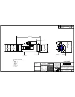
Page 93: ...JAA79471 R 3678 A F2 AF S VRDX 18 200 3 5 5 6G 組立図 Structure of the Lens INC ...

Page 94: ...JAA79471 R 3678 A F3 AF S VRDX 18 200 3 5 5 6G INC ...

Page 95: ...JAA79471 R 3678 A F4 AF S VRDX 18 200 3 5 5 6G INC ...

Page 96: ...OCUS TESTER J18398 AF S VR 18 200 点検 調整ソフト ADJ FD FOR AF S VR18 200 IBM 3 5 J18004 1 J18004用基準ゲージ STANDARD GAUGE FOR J18004 J15306 1 AF I通信ボックス AF I LENS COMMUNICATION BOX CE J15307 AF I通信アダプター COMMUNICATION ADAPTER FOR AF I 自作工具 自作工具 SELF MADE TOOL J11317 2群回螺器 WRENCH FOR 2G AF SVR18 200 J11318 2群押さえ工具 RETAINING TOOL FOR 2G AF SVR18 200 J18399 VR 調整ソフト AF S 18 200VR VR ADJ FD FOR AF S 18 200VR 工具...

Page 97: ... センター用調芯装置 LENS ALIGNMENT EGNIP FOR CENTER J19127P 18 200 用ホルダー ATTACHMENT FOR HOLDER 18 200 J19128 調芯装置用チャート LENS ALIGNMENT CHART J19128A ライトビューワー J19128 用 LIGHT VIEWER J19128 J19129 調芯装置用スライドレール LENZ ALIGNMENT EQUIP SLIDE RAIL 工具設定なし RJNo is not available オシロスコープ OSCILLOSCOP I 40 AFレンズ用グリ ス I 40 GREASE FOR AF LENS EDB0011 ネシ ロック 赤 1401C SCREW LOCK 1401C C 8008B セメダイン 黒 CEMEDAIN 8008 BLACK MZ 800...

Page 98: ...repair parts If there is a defective main PCB after replacements repairs use the defective one Make a self made tool according to the following procedure Making of Self made Tool Main PCB Use this range Connector Remove the mounted parts elements condenser transistor IC etc from the both faces of the PCB within the range of the dotted lines See the left Do not remove the connector The parts elemen...

Reviews: