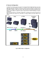
background image


System Configuration Guide 


SV8100 (

R3


Nov

 2009 


NECIC-AP-010 

                                                                                                                      Issue 

3.02 

Summary of Contents for Univerge SV8100

Page 1: ...System Configuration Guide SV8100 R3 Nov 2009 NECIC AP 010 Issue 3 02...

Page 2: ...rsion H Yamashita T Tagawa 2 0 2009 2 5 Add 9 5 inch GW to US AU H Yamashita H Yamashita 3 0 2009 10 16 Add 9 5 inch B E to US H Yamashita H Yamashita 3 01 2009 11 10 Update CD LTA capacity H Yamashit...

Page 3: ...U 24 7 2 Stand Mounting the 19 KSU 25 7 3 Wall Mounting the 19 KSU 26 7 4 Rack Mounting the 19 KSU 27 8 CHS2U GW xx CHS2U B xx CHS2U E 9 5 inch KSU 28 8 1 Wall mounting the 9 5 inch KSU 29 8 2 Stand m...

Page 4: ...vides 104 u law 111 A law timeslots 80 digital terminals and can be expanded using three additional 19 KSU for a maximum of 416 u law 444 A law timeslots 368 digital terminals Through IP connection an...

Page 5: ...via TCP IP SP310 Softphone Fig 1 Simplified View of SV8100 System Connectivity 5...

Page 6: ...IP NIC port Gigabit Ethernet is mountable without additional slots in the KSU The O M NIC port is linked with LAN WAN for inter work with PCPro SMDR OAI server and the VoIP NIC port is linked with LAN...

Page 7: ...s RJ 45 or RJ 61 are located on the front panel of each KSU and Board It increases efficiency of the cabling work Also PCPro provides enhanced user interface Quick Setup tool provides easy setup syste...

Page 8: ...kage EU CHS2U B EU CD CP00 EU CD LTA PZ 2BRIA PZ VM21 AKS InMail EU SV8100 Entry Package AU CHS2U GW AU CD CP00 AU CD LTA SV8100 32 IP Package CHS2U US CD CP00 US PZ 32IPLA SV8100 64 IP Package CHS2U...

Page 9: ...TA CCIS Trunk Interface CD 4DIOPA 4 DID OPX Trunk Interface for US CD 4DIOPB 4 DID OPX Trunk Interface for AU EU OT CH HK LASC CD 4ODTA 4 E M Tie line Trunk Interface for US Trunk Interface Boards CD...

Page 10: ...2U BATT CA INT Battery Cable of Built in Battery Set CHS LARGE BATT BOX Long term Battery Box CHS BATT CA EXT A Batter Cable when installing batteries w o using LARGE BATT BOX External Internal Batter...

Page 11: ...on CPU CNF Conference Bridge Board COT Central Office Trunk COTDB Central Office Trunk Daughter Board on COT CPU Central Processing Unit DID Direct Inward Dialing DIOP DID OPX Board DLC Digital Multi...

Page 12: ...N Adapter analog PVA Packet Voice Application RTB In Skin Router Board SERIAL Serial Port on CPU SLT Single Line Telephone SMDR Station Message Detail Recording TDSW Time Division Switch on CPU USB Un...

Page 13: ...Fig 3 SV8100 System Block Diagram 13...

Page 14: ...SU Number of x1 CPU 2Slots x 1 6 Slots x 2 12 Slots x 3 18 Slots x 4 24 Slots System Maximum PCM 48 104 208 312 416 416 Number of Timeslots U law Data 1 7 7 14 21 28 28 Number of Timeslots A law 64 11...

Page 15: ...o a maximum of 512 ports The 19 KSU consists of a controlling KSU KSU with CPU board and the ability to expand the system using expansion boards depending on system configuration Also new small compac...

Page 16: ...4 Network ed KSUs Number of Slot s for Interface Package 2 Slots w CPU 5 Slots w CPU 6 Slots w o CPU 23 Slots 240 slots Comments CD CP00 xx 1 1 0 1 16 Virtual slot in NetLink is limited to maximum of...

Page 17: ...nal PZ 4COTx or PZ 2BRIA can be installed CD LTB 1 2 Single Line 2 2 2 8 23 An optional PZ 4COTx or PZ 2BRIA can be installed CD 4LCA 4 Single Line Telephone Interface 2 5 6 23 32 Extensions 256 8 x 3...

Page 18: ...200 8 x 25 CD 4DIOPA 4DIOPB 4 DID OPX 2 5 6 23 50 Trunk 200 4 x 50 CD 4ODTA 4ODTB 4 E M 2 5 6 23 50 Trunk 200 4 x 50 CD 2BRIA 2 Basic Rate Interface 2 5 6 23 PZ 2BRIA 2 Basic Rate Interface Daughter...

Page 19: ...t shows each main board and associated daughter board combinations The daughter boards that can be mounted on specific boards are indicated by a checkmark For example the CD LTA can have a PZ 2BRIA or...

Page 20: ...1 PZ 64IPLA 2 PZ 128IPLA 2 Table 5 2 Maximum Number of Package Installed Maximum Number of Package Installed Board Power Factor 9 5 inch Gateway 9 5 Base Exp 19 inch with CD CP00 19 inch without CD C...

Page 21: ...Phase 2 Line PE Type Grounding Requirements No 14 AWG copper wire Feeding Voltage Dterm OPX DID 48V SLT 25mA 28V Output Power Base chassis 130W 4 chassis total 520W Base chassis 136W 4 chassis total 5...

Page 22: ...mum RMS Current Watts Used Idle Watts Used Maximum US 2 19A AU 1 15A Basic Chassis CD CP00 xx Chassis EU OT 1 15A 96W 130W US 4 38A AU 2 3A Basic Chassis Expansion Chassis EU OT 2 3A 192W 260W US 6 57...

Page 23: ...etc In skin Application boards In skin UMS In Skin Router etc It also houses BUS Interface board Power Supply Unit PSU and Cooling FAN When the CD CP00 xx board is installed in the first 19 KSU it is...

Page 24: ...BASE UNIT and the CHS2U JOINT BRACKET KIT Fig7 1 CHS2U Floor Mounting Table 7 1 Hardware for Floor Mounting Installation Description B CODE Feature CHS BASE UNIT BE106406 Floor mount set for all chas...

Page 25: ...pto total 3 KSUs can be stand mounted Fig7 2 1 Stand Mounting of Controlling KSU 2U width Fig7 2 2 Stand Mounting of Controlling KSU and Expansion KSU 6U width Table 7 2 Hardware for Stand Mounting In...

Page 26: ...per system KSU including boards cords power supply etc The KSU is secured to the wall with a wall mount bracket NEC recommends only one KSU per wall mount Fig 7 3 Table 7 3 Hardware for Wall Mounting...

Page 27: ...an be racked mounted by stacking them horizontally The 19 KSU requires two rack mount brackets per KSU for mounting Fig 7 4 1 CHS2U Rack Mount Brackets 2 pcs KIT Fig7 4 2 Fig7 4 3 Table 7 4 Hardware f...

Page 28: ...on the wall or a stand mount Fig 8 A CHS2U GW xx CHS2U B xx Front Rear View In the CHS2U GW xx and CHS2U B xx the CD CP00 xx must be installed in the first slot slot 1 When the CD CP00 xx blade is ins...

Page 29: ...he wall can support the weight of the KSU 25 lbs per system KSU including boards cords power supply etc The KSU is secured to the wall with a supplied wall mount bracket Fig 8 1 1 Wall Mounting for 9...

Page 30: ...SU can be stand mounted using the bracket supplied for wall mount This bracket is not for use with a combined Base CHS2U B xx and Expansion CHS2U E chassis A combined Base and Expansion chassis should...

Page 31: ...and Expansion CHS2U E chassis the IP3 RACK MOUNT BAR SET is required Base and Expansion chassis must be installed vertically for proper air circulation 1 Attach the metal rack mount brackets to each...

Page 32: ...ews at each point Fig 8 3 2 Attach CHS2U B xx and CHS2U E Chassis to Rack Table 8 3 Hardware for 9 5 inch B E Rack Mounting Installation Description B CODE Feature IP3D RACK MOUNT BAR SET BE107556 Rac...

Page 33: ...me Terminal Type of battery CHSGW SMALL BATT BOX Internal Battery 9 5 inch KSU BE107691 Cable with Battery GS YUASA NP0 8 12 or Furukawa Battery FML1208 12V 0 8A JST VHR 2N CHS2U BATT MTG KIT CHS2U BA...

Page 34: ...urce using two batteries can be installed using the CHS2U BATT MTG KIT mounting kit and CHS2U BATT CABLE INT internal cabling CHS2U BATT MTG KIT Backup time 10 Minutes 24 Terminals Fig 9 1 1 Installin...

Page 35: ...optional CHSGW SMALL BATT BOX can be installed to provide external battery power to the 9 5 inch KSU during power failure This CHSGW SMALL BATT BOX can power the system approximately 10 minutes Fig 9...

Page 36: ...is available Fig 9 3 1 External Battery Connectivity Table 9 3 External Battery Configuration Configuration Battery Capacity Number of Batteries Number of CHS LARGE BATT BOX 2U x 1 21AH 3sets of 2 x 1...

Page 37: ...Fig 9 3 2 Inside View of External Battery Box 37...

Page 38: ...PZ 128IPLA a detailed traffic calculation is necessary The following table shows the VoIPDB channels required in each VoIP connection Table 10 VoIPDB Channels Required in Each VoIP Connection Legacy I...

Page 39: ...2MB 16 VM VRS 16 Port VM VRS AKS UM 2G EU 2G 16 UMS EU UMS AKS UM 8G EU UK English Italian German 8G 16 UMS 5 Seat Client AKS VRS OT UK English Chinese Mandarin 256M 16 VRS 16 Port VRS In Mail AKS VRS...

Page 40: ...OFF LK SYS UPGRADE LIC ON ON ON ON OAI Activation SOAI Activation Integration Activation ON OFF LK SYS SOAI LIC or AU LKS SYS INTEGR LIC R2 R2 5 ACD Activation ON OFF LK SYS INACD LIC ON ON ACD P eve...

Page 41: ...PMS ON OFF LKS UMS HOTEL PMS LIC R2 UMS Hospitality Language 1 10 LKS UMS HOTEL LANGUAGE LIC R2 UMS Amis Plus Net NETWORKING ON OFF LKS UMS AMIS PLUS LIC AU LKS UMS NETWOR KING LIC R2 UMS TTS Language...

Page 42: ...PMS LIC F F F F Basic Package ON OFF LKS SYS IP Recorder Basic Pkg LIC F Basic Supervisor Capacity 1 256 LKS SYS IP Recorder Basic Pkg LIC F IP Recorder Basic Port Capacity 1 256 LKS IP Recorder Basic...

Page 43: ...ink supported both as primly and secondary Table 13 MEMDB Limitation Basic System PZ ME50 License 256 License unlimited Megaco Migration w Migration board Cygnus Link More than 8 ports InMail 5 CD LTA...

Page 44: ...circuit is independent from these resources Note 4 When 0 Common is selected at 10 09 and if 14 02 10 Caller ID is set to Yes These DSP resources are allocated to trunk side to monitor Caller ID For e...

Reviews: