NEC Display Solutions of America, Inc.
OL-V463 Installation Guide
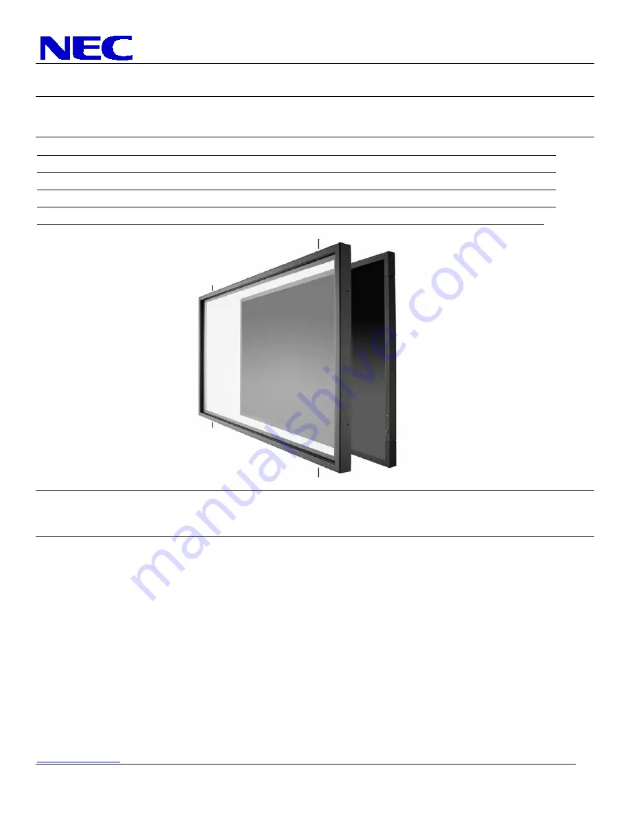
10 Point Touch Overlay for the V463
Rev 1.0
www.necdisplay.com
OL-V463
1
1.0
Contents
Guide Purpose
Page 1
Notes
and
Warnings
Page 1
Equipment
Page 2
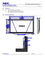
Dimensional
Drawings Page 2
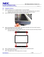
Integration
Procedures
Page 3-4
2.0
Purpose
2.1
This procedure describes the steps to install the OL-V463 IR Touch Overlay onto the V463 display
3.0
Notes and Warnings
3.1
The overlay contains tempered glass. Use caution when handling.
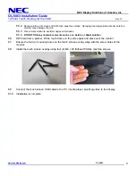
3.2
The overlay has an integrated USB cable located in the bottom right corner. Ensure the cable is not
pinched, crushed, or damaged during installation.
3.3
Installation requires two persons at all times to ensure the touch screen frame does not bend or torque.
3.4
Once the touch screen is installed, do not lift the monitor by grasping or holding the touch screen
overlay.
3.5
Contact NEC Display Solutions support if you have any questions or require additional installation
guidance support.
500 Park Boulevard, Suite 1100
Itasca, IL 60143
Phone: (800) 632-4662


