background image

ISSUED: 04-11-06  SHEET #: 055-9458-2  05-09-06

Visit the NEC Web Site at  www.necsam.com

1 of 9

For customer care call 1-800-729-0307 or 708-865-8870.

 Read instruction sheet before you start installation and assembly.

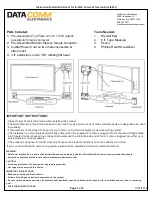
Maximum Load Capacity: 50 lb (22.7 kg)

IMPORTANT! Be sure not to touch the projector while tightening the set screw on the
ball and socket mount. This may cause the image to be unaligned when you let go.

Applications:

Flush Mount .................................................................................................................................................. page 7

Extension Column ........................................................................................................................................ page 8

Installations:

To Wood Joist Finished Ceilings,
Exposed Wood Joists, or Wood Beam Ceilings ........................................................................................ page 5

To Concrete Ceilings .................................................................................................................................... page 6

IMPORTANT!  Turn to the appropriate page for your ceiling installation.

• Make sure that the supporting surface will safely support the combined load of the equipment and all attached hardware and

components.

WARNING

Model:  NP01UCM

Installation and Assembly - Universal Ceiling Mount

Summary of Contents for NP01UCM

Page 1: ...w on the ball and socket mount This may cause the image to be unaligned when you let go Applications FlushMount page 7 ExtensionColumn page 8 Installations To Wood Joist Finished Ceilings Exposed Wood...

Page 2: ...NEC MT860 NEC LT84 NEC MT1060 NEC LT150 NEC MT1060R NEC LT150z NEC MT1065 NEC LT75 NEC Multisync LT245 NEC LT75z NEC NP1000 NEC LT85 NEC NP2000 NEC LT154 NEC V37 NEC LT155 NEC LT380 NEC LT156 NEC VT4...

Page 3: ...x head wood screw 2 5S1 015 C04 G ceiling plate 1 580 4042 H 25 ID x 56 OD x 26 spacer 2 590 2071 I extension column connector with cord management 1 580 4025 J 10 32 x 3 8 socket pin screw 2 520 2084...

Page 4: ...sample illustrated below Attach adapter plate L to projector using one screw M N O or P for each channel as shown below Tighten all screws while keeping the center of gravity Be sure that adapter plat...

Page 5: ...etween ceiling plate G and ceiling Installation To Wood Joist Finished Ceilings Exposed Wood Joists or Wood Beam Ceilings WOOD JOIST CEILING F F G H H Tighten wood screws F so that wall plate G is fir...

Page 6: ...l If mounting to concrete ceiling covered with plaster drywall is unavoidable plaster drywall must be counterbored as shown below WARNING F G CONCRETECEILING concrete anchor Drill hole and insert anch...

Page 7: ...nd secure ball and socket mount A with a M5 x 10 mm socket pin screw C using security allen wrench B as shown in detail 1 Note Slotted set screw K is used to jam against the threads of the ball and so...

Page 8: ...using security allen wrench B See detail 5 Screw ball and socket mount A to extension column connector I Align slot in ball and socket mount A to one of the bottom holes in extension column connector...

Page 9: ...mount A into the adapter plate connection and twisting until the adapter plate will no longer turn about 75 The spring loaded captive screw should line up with a corresponding hole on the adapter pla...

Reviews: