background image

CBZ-001279-048-01 


大切に保管してください 

Keep this manual carefully along with the product


この度は、本製品をお買い上げいただきまして誠にありがとうございます。 

Congratulations for your purchase of this Graphics Card Installation kit. 


本製品を取り扱う前に本書の内容をよく読み、指示に従ってください。また、本製品を取り付ける前に、 
取り付ける本体に添付の「ユーザーズガイド」に記載されている注意事項も参照してください。 また、増
設にあたっては、最寄りの保守サービスセンターに依頼することをお勧めします。 

The User's Guide is intended to allow you to install and use the Graphics Card Installation Kit. 
N8116-48 correctly and safely. Read this manual thoroughly before handling the Kit. 
In addition, refer to this guide whenever you want to know how to use the Kit or some malfunction occurs. 
Always keep this guide at hand so that you can see it when necessary. 
For the server in which the Kit is installed, refer to the User

s Guide of the server. 

Read 

Notes on Use

 carefully before handling the Kit. 


警告 

WARNING


安全上のご注意を無視する取り扱いを行うと、装置の故障、人体事故、火災・周囲の機器の損傷を 
引き起こす原因となることがあります。 

Indicates the presence of a hazard that may result in death or serious personal injury. 

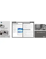
オプションの取り付け、取り外し時は電源プラグをコンセントから抜 

電源プラグを抜く 

き、外部装置と接続しているケーブルを外してください。 

Unplug the power 

故障や感電する恐れがあります。 

cord! 

When  you  install  the  option  or  delete  it,  unplug  the  power  cord  and 

感電注意 

extract the cable that has connected to another one. 
Otherwise, an electric shock or fire may be caused. 

Precaution against 
electric shock 


分解禁止 


Prohibition of 

本書に記載されている場合を除き、絶対に分解したり、修理・改造を 

disassembly 

行ったりしないでください。装置が正常に動作しなくなるばかりで 

発火注意 

なく、感電や火災の危険があります。 

Indicates that 

Do not  disassemble,  repair,  or  modify  the  server.  Otherwise,  an 

improper use may 

electric shock or fire may be caused. 

cause fire. 


感電注意 


Precaution against 


electric shock 


N8116-48

グラフィックスボード搭載キット 

 取り扱いの手引き 

N8116-48 Graphics Card Installation Kit 

 User

s Guide


CBZ-001279-048-01

Summary of Contents for N8116-48

Page 1: ...de of the server Read Notes on Use carefully before handling the Kit 警告 WARNING 安全上のご注意を無視する取り扱いを行うと 装置の故障 人体事故 火災 周囲の機器の損傷を 引き起こす原因となることがあります Indicates the presence of a hazard that may result in death or serious personal injury オプションの取り付け 取り外し時は電源プラグをコンセントから抜 電源プラグを抜く き 外部装置と接続しているケーブルを外してください Unplug the power 故障や感電する恐れがあります cord When you install the option or delete it unplug the power cord and...

Page 2: ...n article 取り付け 6 Installing N8116 48 in Server 1 準備確認事項 6 Preparation point to be checked 2 増設手順 K80 M60 6 Extension procedure of K80 M60 3 増設手順 K40 13 Extension procedure of K40 4 SDR アップデート手順 19 Operating Procedure of SDR Update 5 BIOS 設定手順 K80 M60 21 Operating Procedure of BIOS Setup K80 M60 ...

Page 3: ... 型 HDD ケージは最大 1 台 3 5 型 HDD4 台 まで搭載可能 PXE Boot FC Boot はサポートしておりません K40 搭載時の制限 温度条件は動作時 5 35 N8181 139 電源ユニット 2x1000W の電源ユニット搭載モデル N8181 131 非冗長ファン搭載モデル Composition restriction of K80 M60 Temperature conditions are 5 to 35 N8100 2479F Express 5800 T120g Model N8181 131F Fixed FAN Kit Model N8154 77F 2 5 inch Hot Plug Drive Cage Kit is up to 2set N8154 78F 3 5 inch Hot Plug Drive Cage Kit is up to ...

Page 4: ... Duct Module SCREW SET A 1 リテーナー ダクトモジュール取り付け用 ネジ 3 個 For Retainer Duct Module Three screws M3 For NVIDIA K40 K80 M60 7 グラフィックス ボード固定用ネジ For Graphics Card SCREW SET B 1 ブラケット PCI ブラケット取り付け用 ネジ 5 個 For Bracket PCI Bracket Five screws 6 32UNC For NVIDIA K40 K80 M60 8 SDR UPDATE TOOL Graphics Card Installation Kit 1 SDR アップデート用 CD ROM SDR Update CD ROM For NVIDIA K40 K80 M60 9 取り扱いの手引き User s Guide 1...

Page 5: ...着により静電気を除去 してください また リストストラップを使用する場合は 接地された箇所に接続して使用して ください This internal optional device consists of static sensitive electronic components To avoid failures caused by static electricity when installing or uninstalling the internal optional device wear an anti static wrist strap on your wrist and provide earthing before carrying out the work And also connect a wrist strap to earth ground when you...

Page 6: ...kit is installed on PCI slot 2 3 Please confirm that PCI slot 2 3 are empty If other PCI card is installed on PCI slot 2 3 please move from PCI slot 2 3 2 増設手順 K80 M60 Extension procedure of K80 M60 2 1 ダクトモジュールに DC ケーブル B を取り付けます Attach DC CABLE B to DUCT MODULE and routing into Cable Clamp 2 2 ダクトモジュールのネジ止め用の蓋を開け ネジ止め部分を確認し リテーナー取付用ネジ 3 個にてダクトモジュールをグラフィックスボード K80 M60 に取り付けます リテーナー取付用ネジ 3 か所 Atta...

Page 7: ... 01 7 2 3 サイドカバーを取り外します Remove Side Cover of Chassis 2 4 CPU ダクトを取り外します Remove CPU Duct 2 5 装置本体の 3 個のフロント FAN を取り外します ネジ 6 か所 Remove Front FAN x 3 pcs with 2 screws at 3 portions フロント FAN Front FAN CPU ダクト CPU Duct ...

Page 8: ...CBZ 001279 048 01 8 2 6 電源 FAN ケージを取り外します ネジ 1 か所 Remove PSU FAN Cage with 1 screw 2 7 電源ケージを取り外します ネジ 7 か所 Remove PSU Cage with 7 screws 電源ケージ PSU Cage 電源 FAN ケージ PSU FAN Cage ...

Page 9: ... and Mother Board side Change this cable to DC Cable A DC ケーブル A 接続情報 DC cable A connection 電源ボード PSU BP マザーボード Mother Board エキスパンダカード Expander Card グラフィックスボード Power Graphics Card for K40 K80 M60 グラフィックスボード Power Graphics Card for K80 M60 電源ボード PSU BP マザーボード Mother Board エキスパンダカード Expander Card グラフィックスボード Power Graphics Card for K40 K80 M60 ...

Page 10: ...9 電源ケージを取り付けます ネジ 7 か所 Install PSU Cage with 7 screws 2 10 電源 FAN ケージを取り付けます ネジ 1 か所 Install PSU FAN Cage with 1 screw 2 11 DC ケーブル B とグラフィックスボード K80 M60 を接続します Connect DC CABLE B to Graphics Card K80 M60 DC ケーブル B DC CABLE B ...

Page 11: ...CABLE B 2 13 フロント FAN を取り付けます ネジ 6 か所 Put Front FAN x 3 pcs by 2 screws at 3 portions 2 14 本体底面内側のマイラーをはがし グラフィックスボード K80 M60 を PCI 2 に搭載します Put Graphics Card K80 M60 to PCIe slot 2 And remove Mylar on chassis bottom inside first マイラー Mylar DC ケーブル B DC CABLE B DC ケーブル A DC CABLE A ...

Page 12: ...ュールとブラケットを固定します グラフィックスボード固定用ネジ 5 か所 Put BRACKET align with Chassis bottom guiding hole and screw in 1 screw B with Bracket but not fasten Then fix Graphics Card with 2 screw B on PCI Bracket and then fasten 2 screw B on Chassis bottom Finally fasten screw B on BRACKET 2 16 CPU ダクトを取り付けます Put CPU Duct 2 17 サイドカバーを取り付けます Attach side cover ブラケット BRACKET ...

Page 13: ...ード K40 カードに取り付けます リテーナー取付用ネジ 3 か所 Attach RETAINER to Graphics Card K40 with SCREW SET A 3 screws 3 2 サイドカバーを取り外します Remove Side Cover of Chassis 3 3 CPU ダクトを取り外します Remove CPU Duct CPU ダクト CPU Duct グラフィックスボード K40 Graphics Card K40 リテーナー RETAINER リテーナー ダクト取付用ネジ For Retainer Duct Module SCREW SET A ...

Page 14: ... を取り外します ネジ 6 か所 Remove Front FAN x 3 pcs with 2 screws at 3 portions 3 5 電源 FAN ケージを取り外します ネジ 1 か所 Remove PSU FAN Cage with 1 screw 3 6 電源ケージを取り外します ネジ 7 か所 Remove PSU Cage with 7 screws 電源ケージ PSU Cage 電源 FAN ケージ PSU FAN Cage フロント FAN Front FAN ...

Page 15: ...d and Mother Board side Change this cable to DC Cable A DC ケーブル A 接続情報 DC cable A connection 電源ボード PSU BP マザーボード Mother Board エキスパンダカード Expander Card 電源ボード PSU BP マザーボード Mother Board エキスパンダカード Expander Card グラフィックスボード Power Graphics Card for K40 K80 M60 グラフィックスボード Power Graphics Card for K80 M60 グラフィックスボード Power Graphics Card for K40 K80 M60 ...

Page 16: ...ます ネジ 7 か所 Install PSU Cage with 7 screws 3 9 電源 FAN ケージを取り付けます ネジ 1 か所 Install PSU FAN Cage with 1 screw 3 10 DC ケーブル A とグラフィックスボード K40 を接続します Connect DC CABLE A to Graphics Card K40 DC ケーブル A DC CABLE A グラフィックスボード K40 Graphics Card K40 ...

Page 17: ... first 3 13 ブラケットを本体底面のガイドに従い 本体底面よりグラフィックスボード固定用ネジ 2 個を使用し 固定します PCI ブラケット部分もグラフィックスボード固定用ネジ 2 個を使用し固定します 最後にグラフィックスボード固定用ネジ 1 個を使用しリテーナーとブラケットを固定します グラフィックスボード固定用ネジ 5 か所 Put BRACKET align with Chassis bottom guiding hole and screw in 1 screw B with Bracket but not fasten Then fix Graphics Card with 2 screw B on PCI Bracket and then fasten 2 screw B on Chassis bottom Finally fasten screw B on BRA...

Page 18: ...CBZ 001279 048 01 18 3 14 CPU ダクトを取り付けます Put CPU Duct 3 15 サイドカバーを取り付けます Attach side cover ...

Page 19: ...e server If Press F1 to resume will be displayed please press F1 key 4 5 SDR Update Tool Graphics Card Installation Kit から起動し 自動的に SDR データの 適用が始まります 起動しないときは BIOS のブート順位で CD DVD ROM ドライブが上位になっているか 確認してください 以下のエラーが出たときは 誤ったメディアがセットされています 本オプションに添付 されたメディアを使ってください Error incorrect server platform found SDR データの適用は 起動後 5 6 分かかります System starts from SDR Update Tool Graphics Card Installation Kit CD ROM...

Page 20: ... SDR Revision CFG Identify as follows SDR Revision は SDR Update Tool Graphics Card Installation Kit に記載されて いる Revision であること SDR Revision that described in SDR Update Tool Graphics Card Installation Kit CFG Identify は ccfg1213 グラフィックスボード搭載設定 であること CFG Identify is ccfg1213 This value is Graphics Card support setting 4 7 SDR Update Tool Graphics Card Installation Kit を光ディスクドライブから取り出し R のキーを押します 本機が自...

Page 21: ... 2 POST 中に F2 キーを押します POST 終了後に SETUP が起動して Main メニューが表示されます Press F2 key SETUP will start after POST and the Main menu appears 5 3 Advanced PCI Configuration Above 4GB Decoding Disable の設定を Enable に変更する Advanced PCI Configuration MMIO High Base 56TB の設定を 3TB に変更する Select and modify setting as follows Advanced PCI Configuration Above 4GB Decoding Disable Enable Advanced PCI Configuration MMIO High...

Page 22: ...CBZ 001279 048 01 22 MEMO N8116 48 グラフィックスボード搭載キット 取り扱いの手引き N8116 48 Graphics Card Installation Kit User s Guide CBZ 001279 048 01 ...

Reviews: