CBZ-033514-061-01
N8105-61
グラフィックスアクセラレータ/ Graphics Accelerator
ユーザーズガイド(第 2 版) / User’s Guide(2nd. Edition)
本書を熟読し、大切に保管してください。
Read this document carefully, and keep at hand so that it is available whenever necessary.
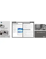
構成品一覧表
/
Packing List
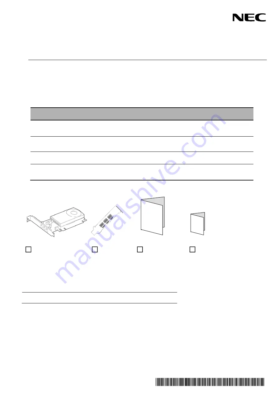
本製品には以下のものが添付されています。確認してください。
This product is shipped with the following items, verify package contents:
品名
Name
数量
Qty.
備考
Memo.
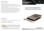
グラフィックスアクセラレータ
Graphics Accelerator
1
ロープロファイル
(
ショート
)
ブラケットを標準装
備しています。
By default, Low-profile (short) size
Bracket is attached.
ブラケット
Bracket
1
交換用ブラケット。大切に保管してください。
Bracket for mounting the slot of different sizes.
Secure this bracket carefully.
スタートアップガイド
Startup Guide
1
保証書
Warranty
1
組込出荷時は添付されません。
本体装置の保証書に記載されます。
Only for using in Japan.
グラフィックスアクセラレータ
Graphics Accelerator
ブラケット
Bracket
スタートアップガイド
Startup Guide
保証書
Warranty
※本カードを本体装置に組み込んでお買い求め頂いた場合、本体装置に添付された保証書が本アダプタの保証書を
兼ねます。
本体装置の保証書に本製品の記載があるかご確認ください。
Note:
This warranty is available only for using in Japan.
Do not use it in any other than Japan.
Summary of Contents for N8105-61
Page 2: ......
Page 21: ......
Page 36: ...J 16 PhysX 構成の設定 サポート外の機能です PhysX の設定をします ...
Page 61: ...E 15 PhysX configuration settings Unsupported Set up PhysX ...