NEC MultiSync X551UHD IGB, User Manual
The NEC MultiSync X551UHD IGB is a cutting-edge display with stunning image quality and vibrant colors. Enhance your visual experience with this user-friendly product. To fully utilize its features, make sure to download the free user manual from manualshive.com to maximize your viewing pleasure.
Share
Download


Reviews:
No comments
Related manuals for MultiSync X551UHD IGB
QuickPanel+ IC754VSI12CTD
Brand: GE Pages: 96
580
Brand: J2 Pages: 38
625
Brand: J2 Pages: 52
225
Brand: J2 Pages: 75
VERSA IC
Brand: IBC Pages: 10
HS2TCHP
Brand: NEO Pages: 36
Frame
Brand: TablerTV Pages: 4
uEZ GUI
Brand: FDI Pages: 30
EntryLine UHD series
Brand: Prowise Pages: 54

Lightcloud Touch
Brand: RAB Lighting Pages: 10
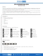
IP-CONSOLE-GH
Brand: Atlas IED Pages: 8
DS-4217TSL
Brand: SunBriteDS Pages: 4
DTH-1320
Brand: Wacom Pages: 11
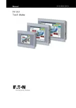
XV100
Brand: Eaton Pages: 80
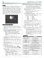
Equinox 73-II
Brand: Vantage Hearth Pages: 4
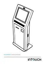
KIO190VRT
Brand: InTouch Pages: 4
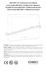
DSC HS2TCHP
Brand: Tyco Pages: 132
CINTIQ DTK-2700
Brand: Wacom Pages: 27


