background image

MM2000

User’s Manual

Multimedia Switcher for DLP Cinema

®

 Projector

NEC Viewtechnology, Ltd.

Summary of Contents for MM2000

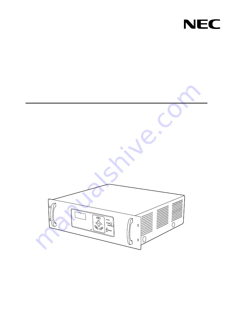
Page 1: ...MM2000 User s Manual Multimedia Switcher for DLP Cinema Projector NEC Viewtechnology Ltd ...

Page 2: ...respective holders WARNING This is a Class A product In a domestic environment this product may cause radio interference in which case the user may be required to take adequate measures CAUTION In order to reduce any interference with radio and television reception use a signal cable with ferrite core attached Use of signal cables without a ferrite core attached may cause interference with radio a...

Page 3: ...afety do not connect to the connector for peripheral device wiring that might have excessive Voltage Do not put the Switcher on its side when the power is turned on Disposing of your used product EU wide legislation as implemented in each Member State requires that used electrical and electronic products carrying the mark left must be disposed of separately from normal household waste This include...

Page 4: ...iale ou une marque commerciale déposée de Microsoft Corporation aux Etats Unis et ou dans d autres pays Les autres noms de produits et de sociétés mentionnés dans ce mode d emploi peuvent être des marques commerciales de leur propriétaire respectif Mesures de sécurité importantes Ces instructions de sécurité garantissent la longévité de votre commutateur et préviennent les risques d incendie et de...

Page 5: ...ectriques et électroniques portant la marque à gauche doivent être mis au rebut séparément des autres ordures ménagères Ceci inclus les projecteurs et leurs accessoires électriques ou lampes Lorsque vous mettez au rebut ces produits veuillez suivre les recommandations des autorités locales et ou demandez conseil au magasin qui vous a vendu le produit Une fois ces produits mis au rebut ils sont rec...

Page 6: ...arzer Sicherung fünf A verwendet werden Wenn dem Gerät ein Netzkabel nicht beiliegt wenden Sie sich bitte an Ihren Händler DLP DLP Cinema und ihre entsprechenden Logos sind Warenzeichen oder eingetragene Warenzeichen von Texas Instruments Windows ist ein eingetragenes Warenzeichen oder Warenzeichen der Microsoft Corporation in den USA und oder anderen Ländern Andere Produkt oder Firmennamen die in...

Page 7: ...cherheitsgründen nicht an den Anschluss der Peripheriegeräte Verbindung an das sie eine zu hohe Spannung führen könnte Stellen Sie den Schalter bei eingeschaltetem Strom nicht vertikal auf Entsorgung Ihres benutzten Gerätes Die EU weite Gesetzgebung wie sie in jedem einzelnen Mitgliedstaat gilt bestimmt dass benutzte elektrische und elektronische Geräte mit dieser Markierung links getrennt vom nor...

Page 8: ...G 3 Important Information MEMO ...

Page 9: ...pand the Image Input Terminals 13 2 5 Connecting to a Network 14 2 6 Connecting the Supplied Power Cable 15 3 Projecting an Image 16 3 1 Turning on the Switcher 16 3 2 Turning off the Switcher 17 4 LCD Menu 18 4 1 Basic operation from LCD screen menu 18 4 2 List of LCD screen menus 19 5 Maintenance 20 5 1 Cleaning the Cabinet 20 6 Appendix 21 6 1 Troubleshooting 21 6 2 Error code list 22 6 3 Compa...

Page 10: ...f the projector This makes it possible to attain images with high bit depth Per pixel Motion Adaptive Noise Reduction When the SDTV signal is input it is possible to cancel out noise without blurring the contours of the image by detecting the noise component in the input image on one pixel basis The residual images in which images flow behind the moving objects will not occur by processing to corr...

Page 11: ...ontents are as follows Multimedia Switcher MM2000 Ferrite clamp core for Power cable RGB cables x2 Power cable x3 Band x2 User s Manual User s Manual Power cable for Japan AC100V Power cable for North America AC120V Power cable for Europe AC230V For Japan ...

Page 12: ...1 Front of the Switcher Control panel See page 5 Handles Ventilation inlet 1 3 2 Rear of the Switcher Ventilation outlet Control terminals Image output terminals See page 6 Image input terminals See page 7 AC INPUT See page 15 Main power switch See page 16 ...

Page 13: ...ON STAND BY Use this button to turn the power on and off when the main power is supplied and the Switcher is in standby mode NOTE To turn on or off the Switcher press and hold this button for a minimum of 1 second 7 POWER Indicator When this indicator is green the Switcher is on when this indicator is orange it is in standby mode 8 STATUS Indicator This indicates the status of the Switcher during ...

Page 14: ...PC using a wireless LAN Please inquire your dealer distributor about use of a wireless LAN card 4 USB port type A This terminal is for the service personnel It is used for maintenance of the switcher 5 Main power switch Set the main power switch to ON to have the unit standby 6 AC IN terminal Connect the AC IN terminal of this unit in the wall outlet using the attached power cable 7 DVI output A t...

Page 15: ... connector of a DVD player or to other equipment 4 ACT Indicator Steady green light Shows that this board is selected 2 SLOT 2 MM RGB MM RGB interface board is standard equipment Make sure to mount the accessory ferrite clamp core to the end of the RGB signal cable The ferrite clamp core should be mounted as close to this unit as possible 1 2 3 1 RGB Input Connectors 5 BNC Type Use a 75 Ω coaxial ...

Page 16: ...video server or video equipment 3 MONITOR OUT Connector BNC type Outputs the signal from the SDI 1 or SDI 2 input you currently select Connect this with a dedicated monitor and use it for checking the input signal Use a 75 Ω coaxial cable 4 ACT Indicator Steady green light Shows that this board is selected NOTE Use the 75 Ω coaxial 5C 2V cable or equivalent Higher quality recommended Using a thinn...

Page 17: ... be within 5 m 196 long To project a DVI digital signal be sure to connect the PC and the Switcher using a DVI D signal cable before turning on your PC or Switcher Turn on the Switcher first and select DVI DIGITAL from the source menu before turning on your PC Failure to do so may not activate the digital output of the graphics card resulting in no picture being displayed Should this happen restar...

Page 18: ...oftware When Viewing a DVI Digital Signal To project a DVI digital signal be sure to connect the PC and the Switcher using a DVI D signal cable before turning on your PC or the Switcher Turn on the Switcher first and select DVI DIGITAL from the source menu before turning on your PC Failure to do so may not activate the digital output of the graphics card resulting in no picture being displayed Sho...

Page 19: ...t terminal DVI B on the projector and the DVI OUT B terminal on this unit using two commercially available DVI D signal cables Alternatively when a mode to control this unit from the projector linked mode is used connect this unit with the projector using a LAN cable DVI D signal cable not supplied LAN cross cable not supplied MM2000 Touch panel controller option NC series projector DVI OUT A DVI ...

Page 20: ...pplied Component video RCA x 3 cable not supplied MM2000 PC DVD player COMPONENT Ferrite clamp core supplied Mounting the ferrite clamp core Use the supplied ferrite clamp core 1 Open the accessory ferrite clamp core and attach it to the cable When doing so attach this as close as possible to end that goes to the switcher Push the catch to open the ferrite clamp core 2 Close the ferrite clamp core...

Page 21: ...crewsandpanelinasafeplace Please do not use the Switcher while the panel is disengaged Foreign matter could enter the interior and cause breakdown 3 Insert the board into the slot rail The example shown in the drawing is the MM SDI board NOTE When inserting the board into the slot insert it so that it moves along the rails located at the right and left of the slot If the board is not positioned be...

Page 22: ...In addition when the switcher is connected with a PC using a LAN cross cable you can use a mode for setting and adjustment of the switcher standalone mode Contact your dealer distributor about use of the switcher in standalone mode Example of Connection with LAN Server PC PC LAN cable not supplied NC series projector Touch panel controller option MM2000 Hub LAN When the switcher and PC are connect...

Page 23: ...ly inserted into both the AC IN and the wall outlet Ferrite clamp core supplied NOTE Always mount the ferrite clamp core to the power cable The ferrite clamp core should be mounted as close to this unit as possible Do not unplug the power cable from the wall outlet or switcher when the switcher is powered on Doing so can cause damage to the AC IN connector of the switcher and or the prong plug of ...

Page 24: ...on Failure to do so may cause damage to the Switcher The Switcher has two power switches main power switch and POWER button Turn on the power switch of the projector connected to the Switcher To turn on the main power to the Switcher press the Main Power switch to the ON position I POWER POWER ON STAND BY Standby Power ON Steady orange light Steady green light Before you turn on your Switcher ensu...

Page 25: ...Standby Steady green light Steady orange light Second turn off the Main Power switch The power indicator will go out Last unplug the power cable NOTE When switching off the Main Power switch set the Switcher to the standby mode beforehand Doing so can cause damage to the Switcher When Please wait is displayed in the LDC screen do not turn off the main power or pull out the power plug from the outl...

Page 26: ...en display When not displaying the menu the following screen is usually displayed When in standby When this unit is in the standby state the following is displayed When power is on When the power is turned on the following is displayed Number of the selected slot S1 to S4 and the board name are displayed Type of the input signal is displayed ...

Page 27: ...he submenu Data by pressing the SELECT 왗왘 button As you press the SELECT 왗왘 button the display changes in a cycle BIOS Firmware Data Serial No and the version information is displayed 5 Press the SELECT 왔 button for several times Every time the SELECT 왔 button is pressed the display returns to the upper tiers one by one 4 2 List of LCD screen menus Description Displays the selected slot number the...

Page 28: ...e Cabinet 1 Turn off the Switcher before cleaning 2 Clean the cabinet periodically with a damp cloth If heavily soiled use a mild detergent Never use strong detergents or solvents such as alcohol or thinner 5 Maintenance ...

Page 29: ...is turned on Select correct option in the Signal Select for current signal For RGB computer input is it a resolution and frequency supported by the input signals Check the resolution of the PC If the PC screen does not project properly see the following pages Use the menus or Source Input button on the remote control to select the source you want to input Characters may blink or color display way ...

Page 30: ... PC screen If you use a laptop PC from a manufacturer not listed in the table refer to your laptop s help menu or your owner s manual When the External Output Signal is Not Correct When Simultaneously Displaying on a Laptop There are instances in which the projected image is not normal even if the image on the laptop screen is normal In many cases it is thought to be caused by the limitations when...

Page 31: ...0 x 1080 1920 x 1080 1920 x 1080 1920 x 1080 1920 x 1080 1920 x 1080 1920 x 1080 Horizontal freq kHz 15 73 15 63 15 73 15 63 31 47 37 86 37 5 43 27 35 16 37 88 48 08 46 88 53 67 48 36 56 48 60 02 68 68 54 35 63 99 67 5 77 49 60 75 85 94 63 98 79 98 91 15 65 32 82 28 93 88 75 81 25 87 5 93 75 100 15 73 15 63 31 47 31 25 45 27 28 13 33 75 27 56 25 67 5 15 73 15 63 45 27 28 13 33 75 33 75 27 28 125 3...

Page 32: ...wer 2 bits 10 bits for all processes for each color excluding RGB and DVI input board Multi directional filter method SDTV HDTV 3 2 2 2 pull down signal animation format compatible type Per pixel motion adaptive method SDTV Multi directional filter method Contrast Enhancement 4 slots One board each for the VIDEO board and analog RGB input board are standard equipment 2 slots are for expansion BNC ...

Page 33: ...nts Canada C UL Approved CSA 60950 1 Meets DOC Canada Class A requirements Australia New Zealand Meets AS NZS CISPR 22 Class A Europe Meets Low Voltage Directive EN60950 1 TÜV GS Approved Meets EMC Directive EN55022 EN55024 EN61000 3 2 EN61000 3 3 RGB signal input board MM RGB Video signal input board MM VIDEO SDI signal input board MM SDI DVI signal input board MM DVI Image switching 2 screen mod...

Page 34: ...2 bits 10 bits pour le traitement de chaque couleur sauf pour les cartes d entrée RGB et DVI Méthode à filtre multi directionnel SDTV HDTV Signal d ajustement 24 images 3 2 2 2 type compatible format d animation Méthode par adaptation d animation par pixel SDTV Méthode par filtre multi directionnel Amplification du contraste 4 fentes Une carte chacune car la carte VIDEO et la carte d entrée RGB an...

Page 35: ...aux exigences de classe A DOC Canada Australie Nouvelle Zélande Conforme aux exigences de classe A AS NZS CISPR 22 Europe Confome à la directive basse tension EN60950 1 agréé TÜV GS Conforme à la directive EMC EN55022 EN55024 EN61000 3 2 EN61000 3 3 Carte d entrée de signal vidéo MM VIDEO Carte d entrée de signal SDI MM SDI Carte d entrée de signal DVI MM DVI Commutation d image 2 modes d écran Co...

Page 36: ... bits 10 Bit für sämtliche Bearbeitungen der einzelnen Farben außer RGB und DVI Input Board Multidirektionales Filterverfahren SDTV HDTV 3 2 2 2 Pulldown Signal kompatibler Typ zum Animationsformat Per pixel motion adaptive Verfahren SDTV Multidirektionales Filterverfahren Kontraststeigerung 4 Schlitze Je eine Karte für den VIDEO Board und für das analoge RGB Input Board gehören zur Standardaussta...

Page 37: ...ht den kanadischen DOC Bestimmungen Klasse A Australien Neuseeland Entspricht den AS NZS CISPR 22 Bestimmungen Klasse A Europa Entspricht den Niederspannungsrichtlinien EN60950 1 TÜV GS geprüft Entspricht der EMC Richtlinie EN55022 EN55024 EN61000 3 2 EN61000 3 3 RGB Signal Input Board MM RGB Videosignal Input Board MM VIDEO SDI Signal Input Board MM SDI DVI Signal Input Board DVI Bildumschaltung ...

Page 38: ...30 6 Appendix 6 5 Cabinet Dimensions Units mm ...

Page 39: ... NEC Viewtechnology Ltd 2006 Printed in Japan Ver 1 08 06 ...

Page 40: ...7N8P6981 Printed on recycled paper MM2000 User s Manual ...

Reviews: