background image

¡ ¡ ¡ ¡ ¡ ¡ ¡ ¡ ¡ ¡ ¡ ¡ ¡ ¡ ¡ ¡ ¡

German

¡ ¡ ¡ ¡ ¡ ¡ ¡ ¡ ¡ ¡ ¡ ¡ ¡ ¡ ¡ ¡ ¡

English

ON/STAND-BY

IR

COM EXT

INPUT 1-7

STILL SPLIT BLUE

PICTURE FUNC. MENU

ENTER

CTL

END

REMOTE

NORMAL

OUTPUT

FORMAT

MONITOR

SYSTEM-A

DISPLAY

1

6

7

8

9

0

2

3

4

5

POWER

 I N1 : V IDEO  NTSC
OUT :DBL   5 25  31 . 5K / 60
MONITOR: IN1  V IDEO
P I C. FNC  COLOR         +11

Summary of Contents for IPS-4000

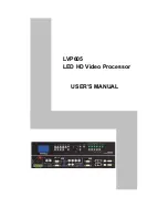
Page 1: ...BY IR COM EXT INPUT 1 7 STILL SPLIT BLUE PICTURE FUNC MENU ENTER CTL END REMOTE NORMAL OUTPUT FORMAT MONITOR SYSTEM A DISPLAY 1 6 7 8 9 0 2 3 4 5 POWER IN1 V IDEO NTSC OUT DBL 5 25 31 5K 60 MONITOR IN1 V IDEO P I C FNC COLOR 11 ...

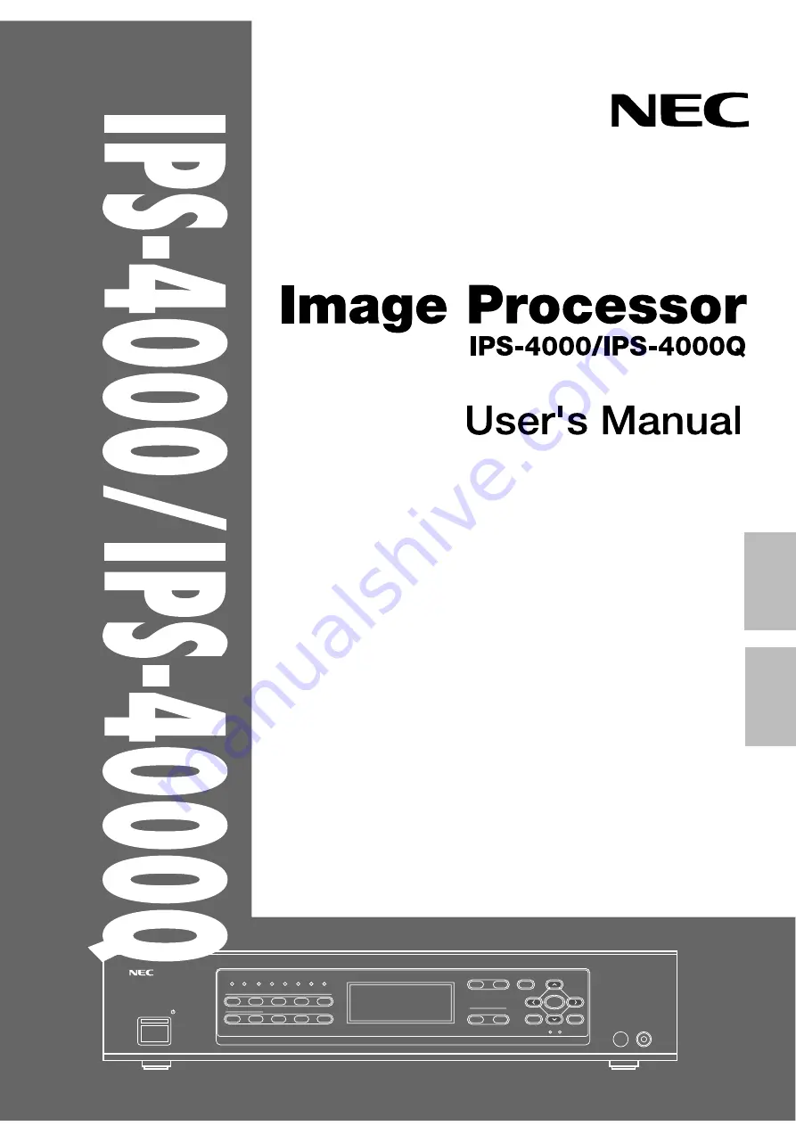
Page 2: ...IPS 4000 IPS 4000Q IPS 4000 IPS 4000Q Image Processor User s Manual English ...

Page 3: ... MOISTURE ALSO DO NOT USE THIS UNIT S POLARIZED PLUG WITH AN EXTENSION CORD RECEPTACLE OR OTHER OUTLETS UNLESS THE PRONGS CAN BE FULLY INSERTED REFRAIN FROM OPENING THE CABINET AS THERE ARE HIGH VOLTAGE COMPONENTS INSIDE REFER SERVICING TO QUALIFIED SERVICE PERSONNEL AVERTISSEMENT AFIN DE REDUIRE LES RISQUES D INCENDIE OU D ELECTROCUTION NE PAS EXPOSER CET APPAREIL A LA PLUIE OU A L HUMIDITE AUSSI...

Page 4: ...se harmful interference to radio or television reception which can be determined by turning the equipment off and on the user is encouraged to try to correct the interference by one or more of the following measures Reorient or relocate the receiving antenna Increase the separation between the equipment and receiver Connect the equipment into an outlet on a circuit different from that to which the...

Page 5: ...pair the unit NEC is not liable for any bodily harm or damage caused if unqualified persons attempt service or open the cabinet Refer all service to an authorized NEC dealer To avoid damage and prolong operating life 1 Use only with 100 240V 50 60Hz AC power supply Continued operation at line voltages other than those specified herein will shorten the life of the unit and might even cause a fire h...

Page 6: ...vice personnel only 31 INSTALLATION OF RACK MOUNT FITTINGS 32 SPECIFICATIONS 33 PC CONTROL COMMAND REFERENCE 34 LIMITED WARRANTY 36 WARNINGS AND SAFETY PRECAUTION 4 FEATURES 6 CHECK OF SUPPLIED ACCESSORIES 7 POWER CABLE CONNECTIONS 8 PART NAMES AND FUNCTIONS Front Panel 9 Setting Indicators 11 LCD Panel 11 Rear Panel 12 Remote Control 14 REMOTE CONTROL NOTES Installing the Remote Control Batteries...

Page 7: ... dimensional scanning line interpolation circuitwhich also supports PAL and SECAM provides a reduction of line flicker and a smooth moving picture image quality for changing still and moving pictures by means of the original interpolation process motion detection Digital video noise reduction circuit greatly improves the signal to noise ratio of the signal and outputs an image permitting 3 stage s...

Page 8: ...ng the carton If anything is missing please contact your NEC authorized dealer RD324 Remote Control 1 unit AAA Batteries 2 Power Cables 100 V AC 10 A 3 m for Japan 1 125 V AC 10 A 3 m for U S A 1 250 V AC 10A 3 m for Europe 1 Remote Control Cable 4 m 1 Rack Mount Fittings 2 User s Manual 1 Black Gray 7 ...

Page 9: ... AC IN REMOTE2 EXTERNAL CONTROL Three types of power cables are supplied with this unit Use the type of power cable that suits the region in which the unit will be used POWER CABLE CONNECTIONS Power cable for Europe 250 V AC Power cable for the U S A 125 V AC 8 To the power outlet ...

Page 10: ...adjustments cannot be selected depending on input signals 5 MENU Button This button selects the following adjustments V APERTURE MOTION STILL NR and SPLIT Press the button to switch between adjustments V APERTURE Selects the vertical edge correction edge enhancement in the vertical direction MOTION Selects the motion detection level provides optimum picture interpolation to the image and prevents ...

Page 11: ...red remote control is received here 10 END Button Not available 11 ENTER Button Sets the various adjustment function selections and closes the adjustment screen 12 CTL Button This is a combined function button that is used in conjunction with other buttons 13 MONITOR Button This button selects the monitor output at the time of selecting INPUT 7 RGB Each press of the button advances the selection o...

Page 12: ...A Indicator Lit green When any of the adjustment items of SYSTEM A differ from the factory preset Unlit When all of the adjustment items of SYSTEM A are the same as the factory preset LCD Panel First Line Display of the format of the input signal Input connector number Input signal Video system Second Line Display of the format of the output signal Scanning system Number of horizontal scanning lin...

Page 13: ...onal computer or other control equipment 5 REMOTE 2 Connector Mini D Sub 15 pin For service personnel only 6 EXTERNAL CONTROL Mini D Sub 15 pin This connector is connected when operating the unit by means of external control See External Control Mode 7 OUTPUT Connectors These connectors are connected to a monitor equipped with RGB connectors such as a multi sync monitor or a projector R G B BNC ty...

Page 14: ...ere are output from the OUTPUT jacks 10 INPUT 6 Connectors COMPONENT Input Y Cr Cb BNC Type These connectors are connected to the color difference output connector of the external equipment AUDIO L R RCA type These jacks are connected with the audio output jacks of the external equipment 11 INPUT 3 4 5 Connectors VIDEO Input VIDEO BNC type These connectors are connected with the video output conne...

Page 15: ...polation to the image and prevents drops in resolution as well as noise STILL Performs Y C separation and picture inter polation suited to still pictures NR Reduces picture noise SPLIT Sets the artificial interlace display to half the screen or the full screen This is used to view the effects of the scanning line interpolation 5 PICTURE FUNC Button This button selects the picture adjustments Each ...

Page 16: ... vertical direction Each press of the button advances the selection one step in the sequence of 0 1 2 3 4 5 6 7 20 LCD Button Switches on and off the LCD s back light Each press advances the selection one step between ON OFF 21 DISPLAY Button Switches the on screen display on and off Each press advances the selection one step between ON OFF 22 FORMAT Button This button selects the format resolutio...

Page 17: ...mote control sensor located at the front of the main unit The remote control system may not function when direct sunlight or strong illumination strikes the remote control sensor of the main unit or when there is an obstacle in the path When remote control buttons are pressed and held main unit operations may not be possible Do not subject to strong shock Do not allow water or other liquid to spla...

Page 18: ...onnectors Remote Control Only Each press of the DISPLAY button advances the setting of the on screen output between ON and OFF The DISPLAY indicator of the main unit will be lit to indicate that this function is ON When an operation is performed notification is provided on the on screen display Press the ENTER button to get rid of the display The displayed information will automatically disappear ...

Page 19: ... the Input Signal These buttons select the equipment connected to the INPUT connectors of this unit Select the input equipment by pressing the main unit INPUT buttons 1 through 7 Buttons 8 9 and 0 do not have a function When INPUT 7 RGB has been selected the output from the MONITOR OUTPUT connector will permit selection of INPUT 1 through 5 and OFF with the MONITOR button When a selection has been...

Page 20: ...he format resolution of the input signal and provides output When a selection has been made the information will be displayed on screen for a while DOUBLER Line double sequential scanning method FIELD DOUBLER Field double interlaced scanning method QUADRUPLER Line quadruple sequential scanning method 800 x 600 Sequential scanning method 1024 x 768 Sequential scanning method IPS 4000Q only FORMAT M...

Page 21: ...t Pressing the button makes the color thinner pressing the button makes the color deeper TINT Tint Adjustment Pressing the button makes the video more red pressing the button makes the video greener Press the button on the remote control which you want to adjust The on screen display of the information associated with that button appears Make the adjust ment with the and CURSOR buttons SHARPNESS P...

Page 22: ...button displays V APERTURE directly on screen Each press of the button advances the selection one step in the sequence of 0 1 2 3 4 5 6 7 Press the or CURSOR button and adjust to the desired level At level 0 V APERTURE will be switched off and as the level number gets larger the effect will become stronger Press the ENTER button to make the display go off Main Unit Operation A press of the MENU bu...

Page 23: ... of settings is SPLIT STILL and MOTION In view of this switch other settings to OFF when setting MOTION Setting STILL Remote Control Operation A press of the STILL button displays STILL directly on screen Each press of the STILL button switches the selection between ON OFF Press the CURSOR button and select ON To cancel select OFF A press of the ENTER button will make the display go off Main Unit ...

Page 24: ...rol Operation A press of the SPLIT button displays SPLIT directly on screen Each press advances the selection one step in the sequence of OFF HALF ALL Press the or CURSOR button and select Main Unit Operation A press of the MENU button will bring up the on screen display Press the MENU button until SPLIT is displayed The selection method is the same as with the remote control Main Unit Operation A...

Page 25: ... is switched on IR RMT CTL This setting determines whether or not the signal from the remote control is received SYNC This sets the output polarity of the sync signal Desired items are selected with the and buttons of the cursor Cr Cb R Y B Y Pr Pb AUTO NTSC 4 43NTSC PAL SECAM ON OFF 00 2 1 0 1 2 SOUND ATT TBC Y C DELAY MATRIX VIDEO FORMAT SYSTEM A 1234 1234 1234 1234 1234 CURSOR CTL ENTER END MEN...

Page 26: ...ENTER button to exit In the absence of key input the on screen display will go out in about 5 seconds Adjustment of Sound Output Level SOUND ATT This function adjusts the level of the audio signal Select SOUND ATT of SYSTEM A then press the or CURSOR button and adjust to the desired level The adjustment range is from 48 to 0 Setting of the Time Base Corrector Function TBC This function turns on or...

Page 27: ... or CURSOR button and select the desired input signal SYSTEM SETTINGS Selection of Input Signal System VIDEO FORMAT ON OFF ON OFF ON OFF ON OFF H V H V H V H V DISPLAY LCD LIGHT AUTO POWER IR RMT CTL SYNC SYSTEM B DBL On Off Switching of the On screen Display DISPLAY This setting switches the on screen display on and off Select DISPLAY of SYSTEM B then press the or CURSOR button and set to ON or O...

Page 28: ...l be set to the standby mode when the main power switch on the rear panel of the main unit is ON On Off Switching of the Infrared Remote Control IR RMT CTL This function sets whether or not to receive the infrared signal from the wireless remote control Select IR RET CTL of SYSTEM B then press the or CURSOR button and set to ON or OFF Sync Signal Polarity Selection SYNC This function sets the pola...

Page 29: ...6 Red ground 14 V sync 7 Green ground 15 Open 8 Blue ground 5 1 4 2 3 10 11 12 13 14 15 6 9 7 8 EQUIPMENT CONNECTION EXAMPLES Video camera or document camera equipped with a video output jack Video equipment Laser disc player or TV tuner The fastening screws of the mini D Sub connector are 4 40 UNC DVD player Personal computer XM37 Plus or other monitor equipped with video jacks or S video jacks X...

Page 30: ... Input Output Signal Name Function 1 I Receive Data 6 I Receive Data 2 O Transmit Data 7 O Transmit Data 11 I Clear to Send 12 I Clear to Send 3 O Request to Send 8 O Request to Send 9 13 O Unit internal use 4 5 10 14 No Connected Not used 15 Signal Ground Ground 5 1 4 2 3 10 11 12 13 14 15 6 9 7 8 422 232C COM SW Using the REMOTE 1 Connector The REMOTE 1 connector is used for connections with per...

Page 31: ... Send Clear to Send To Clear to Send Signal Ground Signal Ground 422 232C COM SW 422 232C COM SW RS 2332C Connector of Personal Computer Switch Position Pin No and Signal Name Input Output Using RS 232C Using RS 422 Switch Position Pin No and Signal Name Input Output RS 422 Connector of Personal Computer 5 1 4 2 3 10 11 12 13 14 15 6 9 7 8 Request to Send From Request to Send Transmit Data From Tr...

Page 32: ...t to Send Transmit Data From Transmit Data Transmit Data From Transmit Data Receive Data To Receive Data Receive Data To Receive Data Clear to Send To Clear to Send Clear to Send To Clear to Send Signal Ground Signal Ground Using the REMOTE 2 Connector The REMOTE 2 connector is used for connections with other control equipment It is used with RS 422 Mini D Sub 15 Pin Used in the data transmission ...

Page 33: ...oved 3 Fasten the unit to the rack with the supplied screws 2 at the left and 2 at the right Rack mount fittings Rack mount fittings installation dimensions 3 15 80 1 75 44 5 1 75 44 5 4 0 28 7 2 X0 4 10 3 19 482 6 18 3 465 Center of fitting mount holes Unit inch mm A A Vents NOTE Allow at least 30mm of space between the inside of the rack and the left side of the IPS 4000 IPS 4000Q Ensure that th...

Page 34: ... S Video output Y signal 1 0 0 1 Vp p with 75Ω termination C signal 0 28 0 03 Vp p with 75Ω termination Burst level Video output 1 0 0 1 Vp p with 75Ω termination L R Output 0 5 0 1 Vrms 0 to 40 dB with termination of 22 kΩ or greater Corresponding to the various video signal outputs REMOTE 1 Linked control PC control RS 232C RS 422 EXT Control TTL level 100 to 240 V AC 50 60 Hz 0 7A 17 W X 13 4 D...

Page 35: ...mand 2 Code allocated to the main functions of the IPS 4000 4000Q Data Length Number of bytes of the data that is transmitted Data Data that is transmitted Check Sum Lower eight digits of sum total of the first byte to the byte just before the last When external equipment such as a personal computer gives the command to the IPS 4000 4000Q the IPS 4000 4000Q returns an ACK So make sure that the ext...

Page 36: ...IT ID COM2 Leng Data 00 Data 01 Data 02 Sum DFH 20H 47H 03H 00H 00H 4A 01H INPUT 1 02H INPUT 2 03H INPUT 3 04H INPUT 4 05H INPUT 5 06H INPUT 6 07H INPUT 7 COM1 UNIT ID COM2 Leng Sum 3FH 20H 47H 00H A6 PC CONTROL COMMAND LIST FOR USE WITH THE IPS 4000 4000Q PC IPS 4000 4000Q IPS 4000 4000Q PC PC IPS 4000 4000Q IPS 4000 4000Q PC Example Input switching VIDEO 1 from the PC to the IPS 4000 4000Q 35 PC...

Page 37: ...ctions supplied with the product b Repair or attempted repair by anyone not authorized by NECTECH c Any shipment of the product claims must be presented to the carrier d Removal or installation of the product e Any other cause which does not relate to a product defect 4 Cartons carrying cases batteries external cabinets magnetic tapes or any acces sories used in connection with the product WHAT WE...

Page 38: ...ANY OTHER DAMAGES WHETHER INCIDENTAL CONSEQUENTIAL OR OTH ERWISE SOME STATES DO NOT ALLOW LIMITATIONS ON HOW LONG AN IMPLIED WARRANTY LASTS AND OR DO NOT ALLOW THE EXCLUSION OR LIMITATION OF INCIDENTAL OR CONSEQUENTIAL DAMAGES SO THE ABOVE LIMITATIONS AND EXCLUSIONS MAY NOT APPLY TO YOU HOW STATE LAW RELATES TO THE WARRANTY This warranty gives you specific legal rights and you may also have other ...

Page 39: ...IPS 4000 IPS 4000Q IPS 4000 IPS 4000Q Bildprozessor Bedienerhandbuch German ...

Page 40: ...iger als 70 dB A WARNUNG ZUR VERMEIDUNG VON FEUER UND ELEKTRISCHEN SCHLÄGEN DARF DAS GERÄT WEDER REGEN NOCH FEUCHTIGKEIT AUSGESETZT WERDEN DER POLARISIERTE STECKER DIESES GERÄTES DARF NUR DANN IN EIN VERLÄNGERUNGSKABEL ODER EINE STECKDOSE EINGESTECKT WERDEN WENN SICH DIE STECKKONTAKTE VOLLSTÄNDIG EINSTECKEN LASSEN ÖFFNEN SIE DAS GERÄT NICHT DA DADURCH IM GERÄT FREILIEGENDE HOCHSPANNUNGSFÜHRENDE TE...

Page 41: ... selbst zu warten oder zu reparieren NEC erklärt sich nicht für entstandene Personen oder Sachschäden verantwortlich wenn unqualifiziertes Personal das Gerät wartet oder das Gehäuse öffnet Überlassen Sie sämtliche Wartungsarbeiten ausschließlich einem autorisierten NEC Fachhändler Zur Vermeidung von Schäden und zur Verlängerung der Lebensdauer 1 Betreiben Sie das Gerät ausschließlich mit 100 240 V...

Page 42: ...ON DER RACK MONTAGEWINKEL 32 TECHNISCHE DATEN 33 REFERENZ DER PC STEUERUNGSBEFEHLE 34 WARNUNGEN UND SICHERHEITSHINWEISE 4 AUSSTATTUNGSMERKMALE 6 ÜBERPRÜFUNG DES MITGELIEFERTEN ZUBEHÖRS 7 NETZKABEL ANSCHLÜSSE 8 BEZEICHNUNG DER TEILE UND DEREN FUNKTIONEN Vorderseite 9 Einstellungsanzeigen 11 LCD Bedienfeld 11 Rückseite 12 Fernbedienungsgerät 14 HINWEISE ZUR FERNBEDIENUNG Einlegen der Batterien in da...

Page 43: ...nsschaltung mit optimaler Interpolation für sowohl PAL als auch SECAM sorgt für eine Reduzierung des Zeilenflimmerns und für eine hervorrangende gleichmäßige Bildqualität beim Wechsel von Stand zu bewegten Bildern Dies wird durch eine Original Interpolationsprozess Bewegungserkennung ermöglicht Eine digitale Video Störunterdrückungsschaltung verbessert den Rauschabstand des Signals und liefert ein...

Page 44: ...ieferte Zubehör Sollte ein Teil fehlen so kontaktieren Sie bitte Ihren Händler Fernbedienung RD324 1 Gerät AAA Batterien 2 Netzkabel 100 V Wechselstrom 10 A 3 m für Japan 1 125 V Wechselstrom 10 A 3 m für USA 1 250 V Wechselstrom 10 A 3 m für Europa 1 Fernbedienungskabel 4 m 1 Rack Montagewinkel 2 Bedienerhandbuch 1 Schwarz Grau ...

Page 45: ...MOTE1 422 232C COM SW POWER AC IN REMOTE2 EXTERNAL CONTROL Diesem Gerät liegen drei verschiedene Netzkabel bei Benutzen Sie das für den Betriebsort des Gerätes passende Kabel NETZKABEL ANSCHLÜSSE Netzkabel für Europa 250 V Wechselstrom Zu der Netzsteckdose ...

Page 46: ...e Einstellpunkt in der Reihenfolge COLOR TINT SHARPNESS angewählt COLOR Einstellung der Farbsättigung TINT Einstellung des Farbtons SHARPNESS Einstellung der Bildschärfe HINWEIS Einige Videoeinstellungen können wegen der Eingangssignale nicht angezeigt werden 5 Menütaste MENU Mit dieser Taste werden die nachfolgenden Einstellungen angewählt V APERTURE MOTION STILL NR und SPLIT Drücken Sie die Tast...

Page 47: ...ndung mit anderen Tasten betätigt wird 13 Monitortaste MONITOR Mit dieser Taste wird der Monitorausgang zum Zeitpunkt des Anwählens von INPUT 7 RGB angewählt Bei jeder Betätigung dieser Taste erscheint der jeweils nächste Eingang in nachfolgend aufgeführter Reihenfolge OFF INPUT 1 INPUT 2 INPUT 3 INPUT 4 INPUT 5 14 Format Taste FORMAT Mit dieser Taste wird das Format Auflösung des Ausgangssignals ...

Page 48: ...tet grün Wenn SPLIT im MENU auf HALF ALL gestellt ist Anzeige aus Wenn OFF 7 Blau Anzeige BLUE Leuchtet grün Wenn B OUT in PICTURE FUNC auf ON gestellt ist Anzeige aus Wenn OFF 8 SYSTEM A Anzeige Leuchtet grün Wenn einer der Einstellpunkte in SYS TEM A von den Ausgangswerten abweicht Anzeige aus Wenn alle Einstellpunkte in SYSTEM A mit den Ausgangswerten identisch sind LCD Bedienfeld Erste Zeile A...

Page 49: ... Personal 6 Externe Steuerung EXTERNAL CONTROL 15 pol Mini D Sub Dieser Anschluß muß dann hergestellt werden wenn Sie das Gerät mit Hilfe einer externen Steuerung betreiben Beziehen Sie sich auf den Abschnitt Externer Steuerungsmodus 7 Ausgangsanschlüsse OUTPUT Diese Anschlüsse werden mit einem Monitor verbunden der mit RGB Steckern ausgestattet ist z B ein Multi Sync Monitor oder ein Projektor R ...

Page 50: ...TPUT Buchsen ausgegeben 10 Anschlüsse INPUT 6 COMPONENT Eingang Y Cr Cb BNC Typ Diese Anschlüsse werden mit dem Farbdifferenz Ausgangsanschluß des externen Gerätes verbunden Hier eingegebene Signale werden von den OUTPUT Anschlüssen ausgegeben AUDIO L R RCA Typ Diese Buchsen werden mit den Audio Ausgangsbuchsen des externen Gerätes verbunden 11 Anschlüsse INPUT 3 4 5 VIDEO Eingang VIDEO BNC Typ Di...

Page 51: ... Abfall der Auflösung sowie Störungen STILL Führt die Y C Trennung und Bildinterpolation passend zum Standbild aus NR Reduziert Bildstörungen SPLIT Stellt das Display der künstlichen Verflechtung auf dem halben oder ganzem Bildschirm ein Dadurch können Sie sich die Effekte der Abtastzeilen Inter polation ansehen 5 Bildfunktionstaste PICTURE FUNC Diese Taste dient zum Anwählen der Bildeinstellungen...

Page 52: ...tikale Auflösung V APERTURE Zum Anwählen der vertikalen Auflösung z B Bildschärfe in vertikaler Richtung Bei jeder Betätigung der Taste wird die jeweils nächste Einstellung in nachfolgend aufgeführter Reihenfolge angezeigt 0 1 2 3 4 5 6 7 20 LCD Taste Zum Ein und Ausschalten der LCD Hintergrundbeleuchtung Bei jeder Betätigung dieser Taste wechselt die Einstellung zwischen ON OFF 21 DISPLAY Taste Z...

Page 53: ... Winkels von 30 Die Fernbedienung funktioniert möglicherweise nicht wenn der Fernbedienungssensor des Hauptgerätes direkter Sonneneinstrahlung oder starkem künstlichen Licht ausgesetzt ist oder wenn sich zwischen dem Sensor und der Fernbedienung ein Gegenstand befindet Wenn Sie die Tasten der Fernbedienung gedrückt halten können die Funktionen des Hauptgerätes möglicherweise nicht ausgeführt werde...

Page 54: ...e Ein und Ausschalten des Bildschirmdisplays Hier können Sie bestimmen ob die Displays für die Einstellungen des Gerätes von den OUTPUT Anschlüssen ausgegeben werden sollen oder nicht Nur Fernbedienung Bei jeder Betätigung der DISPLAY Taste schaltet der Bildschirm Ausgang zwischen ON und OFF Die DISPLAY Anzeige des Hauptgerätes leuchtet um anzuzeigen daß diese Funktion aktiviert ON ist Bei Durchfü...

Page 55: ...ie Tasten 8 9 und 0 haben keine Funktion Wenn INPUT 7 RGB angewählt worden ist erlaubt der Ausgang vom MONITOR OUTPUT Anschluß die Anwahl von INPUT 1 bis 5 und OFF mit Hilfe der MONITOR Taste Wenn eine Auswahl getroffen wurde wird die entsprechende Information für ca 5 Sekunden auf dem Bildschirm angezeigt Anwählen des Monitorausgangs MONITOR BETRIEB DES HAUPTGERÄTES Anwählen des Eingangssignals I...

Page 56: ...at Auflösung des Eingangssignals und sorgt für den Ausgang Wenn eine Auswahl getroffen wurde wird die entsprechende Information einen Moment lang auf dem Display angezeigt DOUBLER Leitungsdoppelabtast Folgeabtastung FIELD DOUBLER Felddoppelabtast Zwischenzeilenabtastung QUADRUPLER Leitungsvierfachabtast Folgeabtastung 800 x 600 Folgeabtastung 1024 x 768 Folgeabtastung Nur IPS 4000Q FORMAT Modell I...

Page 57: ...COLOR Einstellung der Farbsättigung Bei Betätigung der Taste wird die Farbe schwächer und bei Betätigung der Taste tiefer TINT Einstellung des Farbtons Bei Betätigung der Taste wird das Bild roter und bei Betätigung der Taste grüner Drücken Sie die Taste die Sie einstellen möchten auf der Fernbedienung Das Bildschirmdisplay der mit der Taste verbundenen Information erscheint Führen Sie die Einstel...

Page 58: ...r V APERTURE Taste wird V APERTURE direkt auf dem Bildschirm angezeigt Bei jedem Druck dieser Taste ändert sich die Einstellung um jeweils einen Schritt in nachfolgend aufgeführter Reihenfolge 0 1 2 3 4 5 6 7 Drücken Sie die oder CURSOR Taste und stellen Sie den gewünschten Wert ein Beim Wert 0 ist V APERTURE ausgeschaltet und je höher der eingestellt Wert ist desto größer ist auch der Effekt Drüc...

Page 59: ...chaltet sich das Display aus Hauptgerät Betrieb Bei Betätigung der MENU Taste erscheint das Bildschirmdisplay Drücken Sie die MENU Taste bis STILL angezeigt wird Das Ein Ausschalten erfolgt auf gleiche Weise wie beim Fernbedienungsbetrieb HINWEIS Die Einstellung ist nicht möglich wenn Sie SPLIT auf die Position ON gestellt haben Die Rangfolge der Einstellungen lautet SPLIT STILL und MOTION Im Hinb...

Page 60: ... Bewegungserkennungswerts MOTION STILL ist nicht möglich Diese Funktion ist nur bei dem Ausgangsformat DOUBLER verfügbar Das On Screen Display erscheint auch nur wenn das Ausgangsformat DOUBLER ist SPLIT R B CURSOR MENU SPLIT OFF HALF ALL Fernbedienungsbetrieb Bei Betätigung der SPLIT Taste erscheint SPLIT direkt auf dem Bildschirm Bei jedem Druck der Taste erscheint die jeweils nächste Einstellun...

Page 61: ...ät beim Einschalten des Stromes sofort hochgefahren IR RMT CTL Mit dieser Einstellung wird festgelegt ob das Signal von der Fernbedienung empfangen wird oder nicht SYNC Einstellung der Ausgangspolarität des Sync Signals Die gewünschten Menüpunkte werden mit den und Tasten des Cursors angewählt Cr Cb R Y B Y Pr Pb AUTO NTSC 4 43NTSC PAL SECAM ON OFF 00 2 1 0 1 2 SOUND ATT TBC Y C DELAY MATRIX VIDEO...

Page 62: ...hirmdisplay nach etwa 5 Sekunden Mit Hilfe dieser Funktion wird der Pegel des Tonsignals eingestellt Wählen Sie SOUND ATT in SYSTEM A an und drücken Sie dann die oder CURSOR Taste um den gewünschten Pegel einzustellen Die Einstellung ist innerhalb eines Bereiches von 48 bis 0 möglich Mit Hilfe dieser Funktion wird die Zeitbasiskorrektur ein oder ausgeschaltet Wählen Sie TBC in SYSTEM A an und drüc...

Page 63: ...dann die oder CURSOR Taste und wählen Sie anschließend das gewünschte Eingangssignal Anwählen des Eingangssignalsystems VIDEO FORMAT ON OFF ON OFF ON OFF ON OFF H V H V H V H V DISPLAY LCD LIGHT AUTO POWER IR RMT CTL SYNC SYSTEM B DBL Ein Ausschalten des Bildschirmdisplays DISPLAY Diese Einstellung schaltet das Bildschirmdisplay ein und aus Wählen Sie DISPLAY in SYSTEM B und drücken Sie die oder C...

Page 64: ... sich der Hauptnetzschalter auf der Geräterückseite in Position ON befindet OFF Das Gerät setzt sich in den Standby Modus wenn sich der Hauptnetzschalter auf der Geräterückseite in Position ON befindet Ein Ausschalten der Infrarot Fernbedienung IR RMT CTL Mit Hilfe dieser Funktion können Sie festlegen ob das Infrarotsignal von der kabellosen Fernbedienung empfangen werden soll Wählen Sie IR RMT CT...

Page 65: ...n 8 Blaue Erde 5 1 4 2 3 10 11 12 13 14 15 6 9 7 8 ANSCHLUSS BEISPIELE Mit Video Ausgangsbuchse ausgestattete Videokamera oder Dokumentenkamera Videogerät Laser Disc Spieler oder TV Tuner Die Befestigungsschrauben des Mini D Sub Steckers sind 4 40 UNC DVD Spieler Personal Computer XM37 Plus oder anderer mit Video oder S Videobuchsen ausgestatteter Monitor XG135LC oder anderer Projektor der mit ein...

Page 66: ...g Ausgang Signalbezeichnung Funktion 1 I Datenempfang 6 I Datenempfang 2 O Datenübertragung 7 O Datenübertragung 11 I Sendebereitschaft 12 I Sendebereitschaft 3 O Sendeaufforderung 8 O Sendeaufforderung 9 13 O Geräteinterner Betrieb 4 5 10 14 Kein Anschluß Nicht belegt 15 Signalerde Erde 5 1 4 2 3 10 11 12 13 14 15 6 9 7 8 422 232C COM SW Anwendung des REMOTE 1 Anschlußes Der REMOTE 1 Anschluß die...

Page 67: ...t Sendebereitschaft Sendebereitschaft Signalerde Signalerde 422 232C COM SW 422 232C COM SW RS 232C Anschluß eines Personal Computers Schalterposition Pin Nr Und Signalbezeichnung Eingang Ausgang Anwendung von RS 232C Anwendung von RS 422 Schalterposition Pin Nr Und Signalbezeichnung Eingang Ausgang RS 422 Anschluß eines Personal Computers 5 1 4 2 3 10 11 12 13 14 15 6 9 7 8 Sendeaufforderung Von ...

Page 68: ...forderung Datenübertragung Von der Datenübertragung Datenübertragung Von der Datenübertragung Datenempfang Datenempfang Datenempfang Datenempfang Sendebereitschaft Sendebereitschaft Sendebereitschaft Sendebereitschaft Signalerde Signalerde Anwendung des REMOTE 2 Anschlußes Der REMOTE 2 Anschluß ist für den Anschluß von anderen Steuergeräten vorgesehen Er wird zusammen mit dem RS 422 genutzt 15 pol...

Page 69: ...heit Zoll mm Mitte der Montagewinkellöcher A A HINWEIS Mindestens 30 mm Platz muß zwischen der Innenseite des Racks und der linken Seite des IPS 4000 IPS 4000Q gelassen werden Vergewissern Sie sich daß für ausreichend Belüftung gesorgt ist und daß die Luftöffnungen nicht blockiert sind damit keine Hitze im IPS 4000 IPS 4000Q entsteht 1 Entfernen Sie die vier A Schrauben am Hauptgerät 2 Befestigen ...

Page 70: ...mpedanz S Video Ausgang Y Signal 1 0 0 1 Vp p with 75Ω Begrenzung C Signal 0 28 0 03 Vp p mit 75Ω Begrenzung Impulswert Video Ausgang 1 0 0 1 Vp p mit 75 Ω Begrenzung L R Ausgang 0 5 U min 0 bis 40 dB mit Begrenzung von 22 kΩ oder mehr entsprechend der verschiedenen Videosignal Ausgänge REMOTE 1 Anschlußsteuerung PC Steuerung RS 232 C RS 422 EXT Steuerung TTL Wert 100 bis 240 V Wechselstrom 50 60 ...

Page 71: ...000 4000Q zugeordneter Code Daten Übertragene Daten Datenlänge Anzahl der Bytes der übertragenen Daten Prüfsumme Die unteren 8 Ziffern der Gesamtsumme des ersten Byte bis zum vorletzten Byte Wenn ein externes Gerät wie z B ein Personal Computer einen Befehl an den IPS 4000 4000Q sendet gibt der IPS 4000 4000Q eine ACK oder NAK zurück Vergewissern Sie sich daß das externe Gerät diese ACK oder NAK e...

Page 72: ...CK 00H COM1 UNIT ID COM2 Länge Daten 00 Daten 01 Daten 02 Summe DFH 20H 47H 03H 00H 00H 4A 01H INPUT 1 02H INPUT 2 03H INPUT 3 04H INPUT 4 05H INPUT 5 06H INPUT 6 07H INPUT 7 COM1 UNIT ID COM2 Länge Summe 3FH 20H 47H 00H A6 PC STEUERUNGSBEFEHLLISTE FÜR DIE BENUTZUNG DES IPS 4000 4000Q PC IPS 4000 4000Q IPS 4000 4000Q PC PC IPS 4000 4000Q IPS 4000 4000Q PC Beispiel Eingangsschaltung VIDEO 1 vom PC ...

Page 73: ...NEC Corporation Printe in Japan 78409852 ...

Reviews: