

Internal ATAPI DVD-ROM Reader
DV-5700
User’s Manual
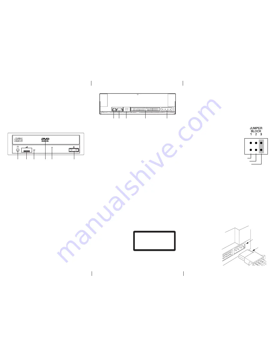
Part Names and Functions
Front View
Rear View
7 DIGITAL OUT Connector
This connector is used to connect Digital Audio to an
audio board.
8 LINE OUT Connector
This connector is used to connect CD-Audio to an
audio board.
9 JUMPER BLOCK
These blocks of jumper set the configuration for the
DVD-ROM reader.
(see Jumper Setting for details)
10 I/O BUS Connector
This BUS connector is used to control the DVD-ROM
reader and data transmission. Use a flat ribbon cable to
connect your computer to the CD- ROM reader.
Connect the colored side of the ribbon cable to the side
marked with the arrow.
11 Power Connector
Use this to provide operating power from the host
computer.
Installation
Jumper Setting
A jumper consists of a pair of pins and a connector which
fits over the pins. When the connector is in place it estab-
lishes an electronic link between the pins, which enables
the function being controlled by the jumper. If the
connector is removed, the electronic link is broken and the
function is disabled.
Jumpers are used to set the
CD- ROM reader mode on the IDE
interface. The factory default setting
is MASTER for fitting to enhanced
IDE controllers supporting two
ports, one for hard disk and one for
DVD-ROM. If you prefer to con-
nect the DVD-ROM reader to the
same port as your harddisk, (as a
secondary device) you have to
change jumper setting to SLAVE
mode.
Installing the DVD-ROM reader in a host PC
1. Turn off the computer, other peripherals and unplug all
the cords and cables. Then remove the computer cover,
face plate, mounting clips, and keeper bracket. Refer to
the Guide to Operations that came with your computer
for help with this step.
2. If necessary, slide other devices above the installation
place out approximately 50 ~ 70mm (2 ~ 3 in.), but do not
disconnect the cables.
3. Slide the DVD-ROM reader into the computer until it is
out approximately 50 ~ 70mm (2 ~ 3 in.).
4. Locate a spare power cable
in your computer.
5. Connect that power
cable to the power
connector on the
back of the
DVD-ROM reader.
1 Phones Jack
This jack is used to connect a set of headphones.
Please use headphones with a stereo mini-jack plug.
2 Volume Control
This control is used to adjust the headphone volume.
NOTE:
This control has no effect on the audio outputs
from the LINE OUT connector on the back of
the DVD-ROM reader.
3 BUSY Indicator
This indicator lights during data read operation.
4 Tray Panel
This Panel prevents dust from entering the DVD-ROM
reader and opens automatically when the Load/Eject
button is pushed.
5 Emergency Eject Hole
Use to remove the disc from the DVD-ROM reader if
the electrical eject is disabled by software or if power
failure occurs.
(see Emergency Eject for details)
6 Load/ Eject Button
This button is pressed to eject or retract the disc tray when
the power is on.
CSEL
SLAVE
MASTER
Laser Safety Information
This drive employs a laser. Do not remove the cover or
attempt to service this device when connected due to the
possibility of eye damage.
CAUTION
Adjustment of control or
following procedures other
than those specified herein
may result in hazardous
radiation exposure.
Laser Specification:
5mW Semiconductor Laser GaAlAs, 770-810nm for CD and
InGaAIP, 635-665nm for DVD (at 25
1
/
2
0
C)
CLASS 1 LASER PRODUCT
LASER KLASSE 1
LUOKAN 1 LASERLAITE
KLASS 1 LASERAPPARAT
This label is located on upper enclosure of this drive.
Power
Connector
Power Cable
10
8
9
11
7
1
6
5
3
2
4


