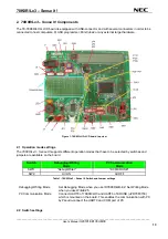
background image


User’s Manual 


78K0R/Lx3 - Sense it! 

 
Demonstration Kit 


Document No. U20191EE1V0UM00


Date Published November 2009 
 

©

 NEC Electronics (Europe) GmbH 

Summary of Contents for 78K0R/L 3 Sense it! Series

Page 1: ...User s Manual 78K0R Lx3 Sense it Demonstration Kit Document No U20191EE1V0UM00 Date Published November 2009 NEC Electronics Europe GmbH ...

Page 2: ...rty or injury including death to persons arising from defects in NEC Electronics products customers must incorporate sufficient safety measures in their design such as redundancy fire containment and anti failure features NEC Electronics products are classified into the following three quality grades Standard Special and Specific The Specific quality grade applies only to NEC Electronics products ...

Page 3: ...ications and or test or application software Thus with respect to Council Directive 89 336 EEC Directive on compliance with the EMC protection requirements this equipment has no autonomous function Consequently this equipment is not marked by the CE symbol EEDT ST 005 10 CAUTION This equipment should be handled like a CMOS semiconductor device The user must take all precautions to avoid build up o...

Page 4: ...EC Electronics Inc U S Santa Clara California Tel 408 588 6000 800 366 9782 Fax 408 588 6130 800 729 9288 NEC Electronics Hong Kong Ltd Hong Kong Tel 2886 9318 Fax 2886 9022 9044 NEC Electronics Europe GmbH Duesseldorf Germany Tel 0211 65 03 0 Fax 0211 65 03 1327 NEC Electronics Hong Kong Ltd Seoul Branch Seoul Korea Tel 02 528 0303 Fax 02 528 4411 Sucursal en España Madrid Spain Tel 091 504 27 87...

Page 5: ...se it _______________________________________________________________________________________________ User s Manual U20191EE1V0UM00 5 Revision History Date Revision Chapter Description 2009 12 12 V1 00 First release ...

Page 6: ...2 3 5 JP5 15 2 3 6 JP6 15 2 4 Connector 15 2 4 1 FP1 15 2 5 Clock 15 2 5 1 Y1 15 2 5 2 Y2 15 2 6 Other Functions 16 2 6 1 VR1 16 2 6 2 J1 16 2 6 3 J2 J3 16 2 6 4 J4 16 2 6 5 J5 16 2 6 6 LED1 16 2 6 7 LED2 16 2 6 8 BUZ1 16 2 6 9 Universal area 16 2 7 LCD Panel 16 2 8 LCD Drive Voltage 18 2 8 1 Booster Type Capacitor Split 18 2 8 2 External Resistor Split 1 2 Bias Method 2 3 Time Sharing 18 2 8 3 Ex...

Page 7: ...tallation on Windows XP 31 6 6 Confirmation of USB Driver Installation 33 7 Flash Programmer WriteEZ5 35 7 1 Device Setup 35 7 2 Using WriteEZ5 36 8 Voice Data Conversion Tool CvADPCM 38 9 78K0R Lx3 Sense it Sample Project 39 9 1 Application Overview Flowchart diagram 39 9 2 Initialization message 40 9 3 Clock mode 40 9 4 Kitchen timer mode 40 9 5 Voltmeter mode 40 9 6 Sensor mode 40 9 7 LCD Evalu...

Page 8: ...78K0R Lx3 Sense it _______________________________________________________________________________________________ User s Manual U20191EE1V0UM00 8 13 Schematics 48 ...

Page 9: ...s Specification 3 Windows 2000 30 Figure 13 Driver File Search Windows 2000 30 Figure 14 USB Driver Installation Completion Windows 2000 31 Figure 15 Found New Hardware Wizard 1 Windows XP 31 Figure 16 Found New Hardware Wizard 2 Windows XP 31 Figure 17 Search Location Specification 1 Windows XP 32 Figure 18 Search Location Specification 2 Windows XP 32 Figure 19 Windows XP Logo Testing Windows XP...

Page 10: ...e 2 SW1 modes 14 Table 3 SW2 modes 14 Table 4 SW3 modes 14 Table 5 SW4 modes 14 Table 6 JP1 settings 15 Table 7 Switch settings Booster Type mode 18 Table 8 Switch settings External Resistor Split mode 1 2 BIAS 18 Table 9 Switch settings External Resistor Split mode 1 3 BIAS 19 Table 10 Switch settings External Resistor Split mode 1 4 BIAS 20 Table 11 TK78K0R LH3 LCD Solder Short Pads 21 Table 12 ...

Page 11: ...If any part is missing or seems to be damaged please contact the dealer from whom you received your 78K0R Lx3 Sense it 1 2 Features NEC Electronics all flash 16 bit 78K0R LH3 MCU µPD78F1508 NEC Electronics µPD78F0730 MCU with on chip USB interface 50 x 8 LCD display Temperature sensor Audio Plug Voice data conversion tool wav Æ c file for ADPCM 78K0R audio library The IAR Embedded Workbench for 78...

Page 12: ...pdates of the IAR Embedded Workbench for 78K documentation and or utilities for 78K0RLX3 SENSEIT if available may be downloaded from the NEC WEB page s at http www eu necel com 78K0RLX3 SENSEIT 1 4 Trademarks IAR Embedded Workbench and C SPY are registered trademarks of IAR Systems AB Microsoft and Windows are registered trademarks of Microsoft Corporation Adobe and Acrobat Reader are registered t...

Page 13: ...ble on the board Switch Debugging Writing Mode PC Communication Mode SW11 Debug Writer K0R K0 USB SW9 All ON All OFF Table 1 78K0R Lx3 Sense It Switch and Jumper settings Debugging Writing Mode Set Debugging Mode when you use ID78K0R QB EZ Set Writing Mode when you use WriteEZ5 PC Communication Mode Connect UART0 of 78K0R LH3 and UART6 of K0 USB uPD78F0730 which is mounted on the board This enable...

Page 14: ...minal Table 3 SW2 modes 2 2 3 SW3 SW3 can select if it uses microcontroller built in operational amplifier 0 or not SW3 Op Amp 0 Remarks ON Use Amplify 10 fold the voltage input to J5 connector by using operational amplifier 0 Set SW2 to Ext Volt side OFF Not Use Not to use operational amplifier 0 Table 4 SW3 modes 2 2 4 SW4 Cursor SW4 is 4 Ways Center push Switch It becomes Low when it is pushed ...

Page 15: ...rrent It is shorted as default 2 3 4 JP4 JP4 is the point to measure consumption current of microcontroller AVDD1 terminal Take off short pin and connect an ampere meter to measure the current It is shorted as default 2 3 5 JP5 JP5 is the point to measure consumption current of microcontroller VDD terminal Take off short pin and connect an ampere meter to measure the current It is shorted as defau...

Page 16: ...xternal Power Supply chapter 2 6 5 J5 J5 is the terminal to connect voltage to be measured It can apply a voltage 0V 2 0V without using operational amplifier and 0 02V 0 22V with using operational amplifier 2 6 6 LED1 LED1 is LED controlled by P33 INTP3 TI07 TO07 It lights by outputting Low 2 6 7 LED2 This is the Power LED It lights up if power is supplied to the board 2 6 8 BUZ1 BUZ1 is a piezoel...

Page 17: ...78K0R Lx3 Sense it Figure 2 LCD Panel Circuit Diagram _______________________________________________________________________________________________ User s Manual U20191EE1V0UM00 17 ...

Page 18: ...terminal following methods can be selected Booster Type 1 3 bias method Booster Type 1 4 bias method Capacitor Split 1 3 bias method 2 8 2 External Resistor Split 1 2 Bias Method 2 3 Time Sharing Set the switches as shown below It is connected with 100KΩ of resistance diagram below SW7 All ON SW6 1 2 Bias Mode SW8 Other Mode Table 8 Switch settings External Resistor Split mode 1 2 BIAS ___________...

Page 19: ...as shown below It is connected with 100KΩ of resistance diagram below SW7 All ON SW6 Other Mode SW8 Other Mode Table 9 Switch settings External Resistor Split mode 1 3 BIAS _______________________________________________________________________________________________ User s Manual U20191EE1V0UM00 19 ...

Page 20: ...ke the picture below To open use cutter to cut the dent part To short put solder on the pad Solder short pad Solder short pad Open Short Solder Short Pad Name Default Connection Short Connect port2 to analog circuit P20 P27 Short Open Use port2 for other purpose Short Connect port32 to the driver of buzzer P32 Short Open Use port32 for other purpose Short Connect port33 to the driver of LED1 P33 S...

Page 21: ...en SW4 1 is set to ON VLC0 Short Open Connect VLC0 not to VDD Table 11 TK78K0R LH3 LCD Solder Short Pads 2 10 External Power Supply A Power supply other than USB is available by using the terminal J2 VDD J3 GND or button battery socket not mounted on the back side of substrate Set the JP1 to 2 3 short and connect a stabilized power supply to the terminal pins J2 VDD and J3 GND Also you can mount b...

Page 22: ...rmal operation mode 3 2 Host computer The USB host interface enables communication to the 78K0R Lx3 Sense It board The μPD78F0730 78K0 8 Bit microcontroller with on chip USB interface and the NEC virtual UART driver allows application software to access the µPD78F1508 device in the same way as it would access a standard RS232 interface The NEC virtual UART driver appears to the windows system as a...

Page 23: ...to program and hear the wanted sound file via a audio output connected to the audio jack mounted on the board 4 2 CD ROM contents 78K0R Lx3 Sense It CD ROM ROOT Acrobat Acrobat Reader for 32Bit Windows OS Doc Documentation Driver TK 78K0R LH3 LCD device driver files IAR Embedded Workbench IAR Embedded Workbench for 78K sample program Example project for the 78K0R Lx3 Sense It Demonstration Kit Wri...

Page 24: ...V0UM00 24 5 Hardware installation After unpacking the 78K0R Lx3 Sense It demonstration kit connect the board via connector USB1 to your host computer using the provided USB interface cable When TK 78K0R LH3 LCD board is connected the USB driver needs to be installed on the host machine Please refer to the following USB Driver Installation ...

Page 25: ...ect Figure 5 78K0R Lx3 Sense It CRROM autorun exe 6 1 IAR Systems Embedded Workbench for 78K installation To install the IAR Systems Embedded Workbench for 78K including C SPY debugger simulator press the regarding button from the Autorun of the CDROM provided within the 78K0R Lx3 Sense It package The installation can also be started by executing the Autorun exe program in the directory IAR Embedd...

Page 26: ... IAR Systems of the CDROM 6 2 IAR Sample project To copy the IAR sample project just press the regarding button IAR sample project The setup dialogues will guide you through the copying process The installation can also be started by executing the IAR_sample_project exe in the directory sample program of the CDROM 6 3 Voice Data Conversion Tool installation To install the CaADPCM Voice Data Conver...

Page 27: ...stalled on the host machine Install the driver according to the following procedure Installation on Windows 2000 Page 27 Installation on Windows XP Page 31 6 5 1 Installation on Windows 2000 1 When the TK 78K0R LH3 LCD board is connected with the host machine the board is recognized by Plug and Play and the wizard for finding new hardware is started Click Next Click Figure 7 Found New Hardware Wiz...

Page 28: ...heck the Specify a location check box only then click Next Check that Specify a location only is checked Click Figure 9 Driver File Location Windows 2000 4 Locate to the folder CDROM Driver _______________________________________________________________________________________________ User s Manual U20191EE1V0UM00 28 ...

Page 29: ... automatic selected then click Open to proceed within driver installation Click Figure 11 Address Specification 2 Windows 2000 6 After the location of the USB driver has been specified click OK to proceed _______________________________________________________________________________________________ User s Manual U20191EE1V0UM00 29 ...

Page 30: ...ws 2000 7 Click Next Figure 13 Driver File Search Windows 2000 Click 8 Click Finish to complete the installation of the USB driver _______________________________________________________________________________________________ User s Manual U20191EE1V0UM00 30 Click ...

Page 31: ...hen click Next Check that No not this time is selected Click Figure 15 Found New Hardware Wizard 1 Windows XP 2 Check that Install from a list or specific location Advanced is selected then click Next Check that Install from a list or specific is selected Click Figure 16 Found New Hardware Wizard 2 Windows XP 3 Check that Search for the best driver in these locations is selected Select the Include...

Page 32: ...4 Locate the folder C CDROM Driver and click OK Figure 18 Search Location Specification 2 Windows XP 5 As shown below NEC Electronics Starter Kit Virtual UART has not passed Windows Logo testing to verify its compatibility with Windows XP is displayed Click Continue Anyway _______________________________________________________________________________________________ User s Manual U20191EE1V0UM00 ...

Page 33: ...ation After installing the USB driver check that the driver has been installed normally according to the procedure below When using the TK 78K0R LH3 LCD board the NEC Electronics Starter Kit Virtual UART should be present like in the figure below Please check in the Windows Device Manager within the Windows Properties Hardware tab that the driver is installed normally _____________________________...

Page 34: ...k that NEC Electronics Starter Kit Virtual UART COM is present Figure 21 Windows Device Manager _______________________________________________________________________________________________ User s Manual U20191EE1V0UM00 34 ...

Page 35: ... information about the device to be programmed only the corresponding flash parameter file must be loaded The parameter file prm for the µPD78F1508 is located on the CDROM in the same folder as the WriteEZ5 setup file Please use the menu Device Setup to open the following dialogue and the button PRM File Read to select the parameter file ____________________________________________________________...

Page 36: ...e Windows Device Manager 7 2 Using WriteEZ5 After a successful device selection the internal flash memory can be blank checked erased programmed or verified WriteEZ5 can be controlled either by menu or by buttons Figure 24 WriteEZ5 Device Menu _______________________________________________________________________________________________ User s Manual U20191EE1V0UM00 36 ...

Page 37: ... program button verity button Autoprocedure button Table 12 WriteEZ4 action buttons WriteEZ5supports Intel Hex and Motorola S record file formats as input file _______________________________________________________________________________________________ User s Manual U20191EE1V0UM00 37 ...

Page 38: ...ing algorithms CCITT Recommendation G 726 40 kbps 32 kbps 24 kbps 16 kbps NEC Electronics ADPCM SP 32 kbps 24 kbps 16 kbps NEC Electronics ADPCM SP2 32 kbps 16 kbps Note CvADPCM can be used on a PC on which Windows XPTM or Windows VistaTM correctly runs This tool may not run on Windows 2000 because it uses the functions of DirectX Figure 25 Voice Data Conversion Tool CvADPCM For further informatio...

Page 39: ...oduction or current measuring of the different operation modes of the target device Furthermore the LCD mounted on the TK 78K0R LH3 LCD is used to guide the user through the available functions of the sample project 9 1 Application Overview Flowchart diagram Initialization of Hardware Initialization of each module Power supply state detection Timer processing Top menu Key processing Clock mode pro...

Page 40: ... operational amplifier 9 6 Sensor mode When the Sensor mode is selected the LCD shows up the measured temperature The temperature is measured by a temperature sensor that is connected to an A D converter input of the 78F1508 microcontroller The result of the 12 bit A D conversion is used as PWM duty cycle to control the brightness of LED1 The temperature can be displayed on the LCD in Celsius as w...

Page 41: ...play anything while it is functioned Make a key input to back to normal mode Main Halt Stop kitchen timer and other functions and change to HALT mode LCD does not display anything while it is functioning Make a key input to back to normal mode Sub Halt Stop kitchen timer other functions and main system clock switch the CPU clock to sub system clock and change to HALT mode LCD does not display anyt...

Page 42: ...the hard drive of your Host PC as described in chapter 6 2 you shall be able to run this sample project To start the IAR Embedded Workbench 16K Kickstart for 78K click Start Æ All Programs Æ IAR Systems Æ IAR Embedded Workbench for 78K v4 62 Kickstart Æ IAR Embedded Workbench The Embedded Workbench Startup screen comes up To open the sample project workspace press the Open existing workspace butto...

Page 43: ...hat MINICUBE is selected as Debugger Driver Therefore open the Debugger settings by clicking Project Æ Options and select the Category Debugger Figure 28 IAR Embedded Workbench Debugger Settings _______________________________________________________________________________________________ User s Manual U20191EE1V0UM00 43 ...

Page 44: ...and the program shall be stopped at the beginning of the main function Figure 29 IAR C SPY debugger window To run the application press the Run button Now you can control the application as described in the chapter above Furthermore all standard IAR C SPY debugger functionalities for a MINICUBE debug session are available For further information about the IAR tools please refer to the regarding IA...

Page 45: ...t 11 Cables 11 1 USB interface cable Mini B type Figure 30 USB interface cable Mini B type _______________________________________________________________________________________________ User s Manual U20191EE1V0UM00 45 ...

Page 46: ... JP3 JP4 JP5 J5 JP6 FFC 2AMEP1 HONDA 20 1 J1 LGY6502 0900FC SMK 21 1 J2 T 16 Red SATO PARTS 22 1 J3 T 16 Black SATO PARTS 23 0 J4 1060 Keystone 24 0 J6 FFC4 4AMEP1 HONDA 25 1 LCD1 A45A005X JSC 26 1 LED1 SLR 56DU ROHM 27 1 LED2 PG1112H ROHM 28 1 L1 MPZ1608R391A TDK 29 1 L2 BLM41PG750S Murata 30 1 MR1 CN1E4K 105J KOA 31 6 R1 R2 R6 R7 R8 R15 43K 32 1 R3 22 33 12 R4 R11 R14 R18 R20 R21 R22 R23 R28 R32...

Page 47: ..._______________________________________________________ User s Manual U20191EE1V0UM00 47 57 1 U8 SN74LVC1G125DCK TI 58 1 U9 SN74LVC2T45DCU TI 59 1 VR1 CT6 EP20K 203 COPAL 60 1 Y1 CSTLS20M0X51 B0 Murata 61 1 Y2 SSP T7 FL 3 7pF SII 62 1 Y3 CSTCE16M0V53 R0 Murata ...

Page 48: ..._____________________ User s Manual U20191EE1V0UM00 48 13 Schematics Please find the schematics attached to this document To open the attachments view in the Adobe Reader press the paper clip in the lower left corner of the program window To open the attachment double click the 78K0RLH3_LCD pdf ...

Page 49: ...78K0R Lx3 Sense it _______________________________________________________________________________________________ User s Manual U20191EE1V0UM00 49 MEMO ...

Reviews: