NEC 42XP10 - PlasmaSync - 42" Plasma Panel, User Manual
The NEC 42XP10 PlasmaSync is a remarkable 42-inch plasma panel, ideal for installation in both residential and commercial settings. Unlock the full potential of this cutting-edge display by downloading the comprehensive installation manual, available for free. Simply visit manualshive.com to access and download this essential manual.
Share
Download


Reviews:
No comments
Related manuals for 42XP10 - PlasmaSync - 42" Plasma Panel

P42LV6-T1
Brand: Haier Pages: 48

440
Brand: Samsung Pages: 2

PlasmaSync 42XR4
Brand: NEC Pages: 3

TH42PH20U - 42" PLASMA TV
Brand: Panasonic Pages: 26

VIERA TX-P42S10B
Brand: Panasonic Pages: 3

Viera TC-P42S1
Brand: Panasonic Pages: 29

TC-42PX14 - 42" Plasma Panel
Brand: Panasonic Pages: 56

TC-P58S1 - 58" Plasma TV
Brand: Panasonic Pages: 58

TC-P42C1 - 41.6" Plasma TV
Brand: Panasonic Pages: 60

4550
Brand: Samsung Pages: 42

TCL37D2 - 37" LCD TV
Brand: Panasonic Pages: 54

TH-C50HD18
Brand: Panasonic Pages: 48

TC-P50X1
Brand: Panasonic Pages: 54

TC-P50X1
Brand: Panasonic Pages: 58

TH-65PV500B
Brand: Panasonic Pages: 60

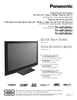
VIERA TH-42PZ800U
Brand: Panasonic Pages: 54

TC-P65V10
Brand: Panasonic Pages: 146
VIERA TH-42PZ800U
Brand: Panasonic Pages: 58


