background image

M

Motorola RFS Series Wireless LAN Switches

WiNG System Reference Guide

Summary of Contents for RFS Series

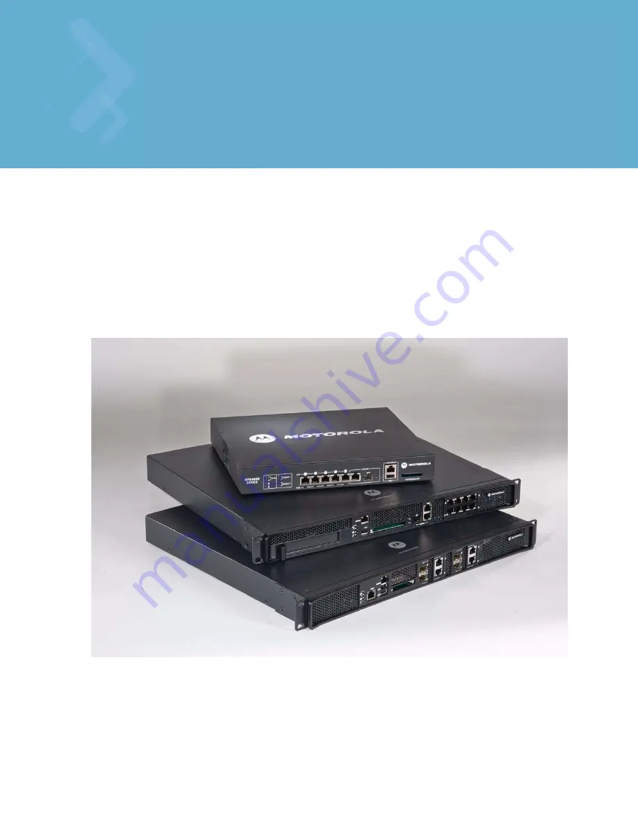
Page 1: ...M Motorola RFS Series Wireless LAN Switches WiNG System Reference Guide ...

Page 2: ... reserved MOTOROLA and the Stylized M Logo are registered in the US Patent Trademark Office Symbol is a registered trademark of Symbol Technologies Inc All other product or service names are the property of their respective owners ...

Page 3: ...3 2 3 Upgrading the Switch Image 2 3 2 4 Auto Installation 2 3 2 5 AP 4131 Access Point to Access Port Conversion 2 5 Chapter 3 Switch Information 3 1 Viewing the Switch Interface 3 1 3 1 1 Setting the Switch Country Code 3 2 3 1 2 Viewing the Switch Configuration 3 2 3 1 3 Switch Dashboard Details 3 4 3 1 4 Viewing Switch Statistics 3 11 3 2 Viewing Switch Port Information 3 13 3 2 1 Viewing the ...

Page 4: ...t 4 10 4 3 3 Viewing and Configuring Ports by VLAN 4 11 4 4 Configuring Switch Virtual Interfaces 4 13 4 4 1 Configuring the Virtual Interface 4 13 4 4 2 Viewing Virtual Interface Statistics 4 16 4 5 Viewing and Configuring Switch WLANs 4 21 4 5 1 Configuring WLANs 4 21 4 5 2 Viewing WLAN Statistics 4 60 4 5 3 Configuring WMM 4 65 4 5 4 Configuring the NAC Inclusion List 4 70 4 5 5 Configuring the...

Page 5: ...170 4 12 1 Wired Hotspot Configuration 4 170 Chapter 5 Switch Services 5 1 Displaying the Services Interface 5 2 5 2 DHCP Server Settings 5 3 5 2 1 Configuring the Switch DHCP Server 5 4 5 2 2 Viewing the Attributes of Existing Host Pools 5 10 5 2 3 Configuring Excluded IP Address Information 5 11 5 2 4 Configuring the DHCP Server Relay 5 13 5 2 5 Viewing DDNS Bindings 5 15 5 2 6 Viewing DHCP Bind...

Page 6: ...APs AP Reported 6 7 6 2 4 Unauthorized APs MU Reported 6 8 6 2 5 AP Containment 6 9 6 3 Wireless Intrusion Detection Protection 6 10 6 3 1 Configuring Wireless Intrusion Detection Protection 6 10 6 3 2 Viewing Filtered MUs 6 12 6 4 Configuring Firewalls and Access Control Lists 6 14 6 4 1 ACL Overview 6 15 6 4 2 Attaching an ACL on a WLAN Interface Port 6 19 6 4 3 Attaching an ACL Layer 2 Layer 3 ...

Page 7: ...04 6 8 7 Viewing Radius Accounting Logs 6 107 6 9 Creating Server Certificates 6 108 6 9 1 Using Trustpoints to Configure Certificates 6 109 6 9 2 Configuring Trustpoint Associated Keys 6 117 6 10 Configuring Enhanced Beacons and Probes 6 119 6 10 1 Configuring the Beacon Table 6 119 6 10 2 Configuring the Probe Table 6 122 6 10 3 Reviewing Found Beacons 6 123 6 10 4 Reviewing Found Probes 6 124 C...

Page 8: ... Support Web Site A 1 A 3 Regulatory Table Update and FCC DFS2 A 1 A 3 1 Outdoor SKU Support for AP650 A 2 B 1 Adaptive AP Overview B 3 B 1 1 Where to Go From Here B 3 B 1 2 Adaptive AP Management B 4 B 1 3 Types of Adaptive APs B 4 B 1 4 Licensing B 5 B 1 5 Switch Discovery B 5 B 1 6 Securing a Configuration Channel Between Switch and AP B 6 B 1 7 Adaptive AP WLAN Topology B 6 B 1 8 Configuration...

Page 9: ...owser not able to contact the agent C 7 C 2 2 Not able to SNMP WALK for a GET C 8 C 2 3 MIB not visible in the MIB browser C 8 C 2 4 SNMP SETs not working C 8 C 2 5 Not receiving SNMP traps C 8 C 2 6 Additional Configuration C 8 C 3 Security Issues C 8 C 3 1 Switch Password Recovery C 8 C 3 2 RADIUS Troubleshooting C 9 C 3 3 Troubleshooting RADIUS Accounting Issues C 11 C 4 Rogue AP Detection Trou...

Page 10: ...TOC 8 Motorola RF Switch System Reference Guide ...

Page 11: ...ence Describes configuration of the Motorola RF Switches using the Web UI Motorola RFS Series Wireless LAN Switches WiNG CLI Reference Describes the Command Line Interface CLI and Management Information Base MIB commands used to configure the Motorola RF Switches RF Management Software Users Guide Describes how to use Motorola RFMS to set up and monitor your switch in respect to areas of good RF t...

Page 12: ...ox and radio button names Icons on a screen GUI text is used to highlight the following Screen names Menu items Button names on a screen bullets indicate Action items Lists of alternatives Lists of required steps that are not necessarily sequential Sequential lists e g those that describe step by step procedures appear as numbered lists CAUTION Indicates conditions that can cause equipment damage ...

Page 13: ... their destination All data packets to and from wireless devices are processed by the switch where appropriate policies are applied before they are decapsulated and sent to their destination Access port configuration is managed by the switch through a Web UI Graphical User Interface GUI SNMP or the switch Command Line Interface CLI SWITCH NOTE The discussion of the switch GUI within this guide is ...

Page 14: ...d routes the packets to their destinations Access ports do not have software or firmware upon initial receipt from the factory When the Access Port is first powered on and cleared for the network the switch initializes the Access Port and installs a small firmware file automatically Therefore installation and firmware upgrades are automatic and transparent 1 1 1 Physical Specifications The physica...

Page 15: ...d is not supplied with a RFS4000 RFS6000 or RFS7000 model switch Use only a correctly rated power cord certified for the country of operation Operating Temperature 0 C 40 C 32 F 104 F Operating Humidity 5 85 RH non condensing ...

Page 16: ...s on the front panel of the switch The console cable included with the switch connects the switch to a computer running a serial terminal emulator program to access the switch s Command Line Interface CLI for initial configuration An initial configuration is described within the Installation Guide shipped with each switch 1 2 Software Overview The switch includes a robust set of features The featu...

Page 17: ... the ability to easily revert to a previous image 1 2 1 2 Configuration Management The switch supports the redundant storage of configuration files to protect against corruption during a write operation and ensure at any given time a valid configuration file exists If writing the configuration file fails it is rolled back and a pre write file is used Text Based Configuration The configuration is s...

Page 18: ...collects statistics for RF activity Ethernet port activity etc RF statistics include roaming stats packet counters octets tx rx signal noise SNR retry and information for each MU 1 2 1 5 Tracing Logging Log messages are well defined and documented system messages with various destinations They are numbered and referenced by ID Each severity level group can be configured separately to go to either ...

Page 19: ...e reporting switch is capable of displaying cluster performance statistics for all members in addition to their own Centralized redundancy group management using the switch CLI For more information on configuring the switch for redundancy support see Configuring Switch Redundancy Clustering on page 5 33 1 2 1 9 Secure Network Time Protocol SNTP Secure Network Time Protocol SNTP manages time and or...

Page 20: ...1 Adaptive AP An adaptive AP AAP is an AP 5131 or AP 7131 Access Point adopted by a wireless switch The management of an AAP is conducted by the switch once the Access Point connects to the switch and receives its AAP configuration An AAP provides local 802 11 traffic termination local encryption decryption local traffic bridging tunneling of centralized traffic to the wireless switch The connecti...

Page 21: ... all devices This feature is enabled automatically when the country code indicates that DFS is required for at least one of the frequency bands that are allowed in the country TPC Transmit Power Control TPC meets the regulatory requirement for maximum power and mitigation for each channel TPC functionality is enabled automatically for every AP that operates on the channel 802 11bg Dual mode b g pr...

Page 22: ...hem to authenticate before granting access to the WLAN The following is a typical sequence for hotspot access 1 A visitor with a laptop requires hotspot access at a site 2 A user ID Password and hotspot ESSID is issued by the site receptionist or IT staff 3 The user connects their laptop to this ESSID 4 The laptop receives its IP configuration via DHCP 5 The user opens a Web browser and connects t...

Page 23: ...Overview 1 11 User based VLAN assignment Allows the switch to extract VLAN information from the Radius server User based QoS Enables QoS for the MU based on settings within the Radius Server ...

Page 24: ...ximum level This allows the Tx Power to be increased when there is a need to increase coverage when an AP fails When an AP fails the Tx Power Supported rates of APs neighboring the failed AP are adjusted The Tx power is increased and or Supported rates are decreased When the failed AP becomes operational again Neighbor AP s Tx Power Supported rates are brought back to the levels before the self he...

Page 25: ...umber of WLANs per switch The maximum number of Access Ports adopted per switch The maximum number of MUs per switch The maximum number of MUs per Access Port The actual number of Access Ports adoptable by a switch is defined by the switch licenses or the total licenses in the cluster in which this switch is a member 1 2 2 10 AP and MU Load Balancing Fine tune a network to evenly distribute data a...

Page 26: ...tion is not shared between the switches nor are buffered packets on one switch transferred to the other Pre authentication between the switch and MU allows faster roaming Interswitch Layer 3 Roaming Interswitch Layer 3 roaming allows MUs to roam between switches which are not on the same LAN or IP subnet without the MUs or the rest of the network noticing This allows switches to be placed in diffe...

Page 27: ...ittle value QoS provides policy enforcement for mission critical applications and or users that have critical bandwidth requirements when the switch s bandwidth is shared by different users and applications QoS helps ensure each WLAN on the switch receives a fair share of the overall bandwidth either equally or as per the proportion configured Packets directed towards MUs are classified into categ...

Page 28: ...Priority Spectralink Prioritization VOIP Prioritization IP ToS Field Multicast Prioritization Data QoS The switch supports the following data QoS techniques Egress Prioritization by WLAN Egress Prioritization by ACL DCSCP to AC Mapping The switch provides arbitrary mapping between Differentiated Services Code Point DCSCP values and WMM Access Categories This mapping can be set manually ...

Page 29: ...d the AP delivers buffered frames associated with that flow during an unscheduled service period The switch initiates an unscheduled service period by transmitting a trigger frame A trigger frame is defined as a data frame e g an uplink voice frame associated with an uplink flow with UPSD enabled After the AP acknowledges the trigger frame it transmits the frames in its UPSD power save buffer addr...

Page 30: ...t buffer queue size scales linearly to accommodate a potential increase in the broadcast packet stream Roaming within the Switch When a MU is assigned to a VLAN the switch registers the VLAN assignment in its credential cache If the MU roams it is assigned back to its earlier assigned VLAN The cache is flushed upon detected MU inactivity or if the MU associates over a different WLAN on the same sw...

Page 31: ... by class The DHCP Server can associate multiple classes to each pool Each class in a pool is assigned an exclusive range of IP addresses DHCP clients are compared against classes If the client matches one of the classes assigned to the pool it receives an IP address from the range assigned to the class If the client doesn t match any of the classes in the pool it receives an IP address from a def...

Page 32: ... 2 4 Management Features The switch supports the following management features A secure browser based management console A Command Line Interface CLI accessible via the serial port or through Telnet or a Secure Shell SSH application A CLI Service mode enabling the capture of system status information that can be sent to Motorola personnel for use in problem resolution The support for Simple Networ...

Page 33: ...P WEP Wired Equivalent Privacy WEP is an encryption scheme used to secure wireless networks WEP was intended to provide comparable confidentiality to a traditional wired network hence the name WEP had many serious weaknesses and hence was superseded by Wi Fi Protected Access WPA Regardless WEP still provides a level of security that can deter casual snooping For more information on configuring WEP...

Page 34: ...eyGuard on page 4 55 1 2 5 2 MU Authentication The switch uses the following authentication schemes for MU association Kerberos 802 1x EAP MAC ACL Refer to Editing the WLAN Configuration on page 4 25 for additional information Kerberos Kerberos allows for mutual authentication and end to end encryption All traffic is encrypted and security keys are generated on a per client basis Keys are never sh...

Page 35: ...a WLAN see Editing the WLAN Configuration on page 4 25 1 2 5 5 802 1x Authentication 802 1x Authentication cannot be disabled its always enabled A factory delivered out of the box AP300 supports 802 1x authentication using a default username and password EAP MD5 is used for 802 1x When you initially switch packets on an out of the box AP300 port it immediately attempts to authenticate using 802 1x...

Page 36: ... vulnerabilities Basic forms of this behavior can be monitored and reported without needing a dedicated WIPS When the parameters exceed a configurable threshold the switch generates an SNMP trap and reports the result via the management interfaces Basic WIPS functionality does not require monitoring APs and does not perform off channel scanning 1 2 5 7 Rogue AP Detection The switch supports the fo...

Page 37: ... processes this information SNMP Trap on discovery An SNMP trap is sent for each detected and Rogue AP Rogue APs are only detected and notification is provided via a SNMP trap Authorized AP Lists Configure a list of authorized Access Ports based on their MAC addresses The switch evaluates the APs against the configured authorized list after obtaining Rogue AP information from one of the 2 mechanis...

Page 38: ...providing authentication and encryption over the Internet Unlike SSL which provides services at layer 4 and secures two applications IPsec works at Layer 3 and secures the network Also unlike SSL which is typically built into the Web browser IPsec requires a client installation IPsec can access both Web and non Web applications whereas SSL requires workarounds for non Web access such as file shari...

Page 39: ...gement is used to provide a standardized procedure to Generate a Server certificate request and upload the server certificate signed by certificate authority CA Uploading of CA s root certificate Creating a self signed certificate Certificate management will be used by the applications HTTPS VPN HOTSPOT and Radius For information on configuring switch certificate management see Creating Server Cer...

Page 40: ...dard is fully supported on the following AP Platforms AP300 Access Port AP5131 Access Point AP5181 Access Point AP7131 Access Point IEEE 802 11b Yes The IEEE 802 11b standard is fully supported on the following Switch Platforms WS2000 WS5100 RFS6000 RFS7000 The IEEE 802 11b standard is fully supported on the following AP Platforms AP100 Access Port AP4131 Access Port AP300 Access Port AP5131 Acces...

Page 41: ...forms AP300 Access Port AP5131 Access Point AP5181 Access Point AP7131 Access Point IEEE 802 11d Yes The IEEE 802 1d standard is implemented as part of the IEEE 802 1sstandardonthefollowing Switch Platforms WS5100 RFS6000 RFS7000 The IEEE 802 11d standard is implemented for Mesh networking on the following AP Platforms AP5131 Access Point AP5181 Access Point AP7131 Access Point IEEE Standard Suppo...

Page 42: ...he following Switch Platforms WS2000 WS5100 RFS6000 RFS7000 TheIEEE802 11istandardisfully supported on the following AP Platforms AP300 Access Port AP5131 Access Point AP5181 Access Point AP7131 Access Point IEEE 802 11n Yes The IEEE 802 11n standard is fully supported on the following Switch Platforms WS5100 RFS6000 RFS7000 The IEEE 802 11n standard is fully supported on the following AP Platform...

Page 43: ...the following EAP methods EAP TLS EAP GTC PEAPv1 EAP MSCHAPv2 PEAPv0 EAP TTLS MD5 PAP MSCHAPv2 When using an external RADIUS server the EAP type is transparent to the WLAN infrastructure allowing any standard EAP method to be supported The IEEE 802 1x standard is fully supported on the following Switch Platforms WS2000 WS5100 RFS6000 RFS7000 The IEEE 802 1x standard is fully supported on the follo...

Page 44: ...P300 Access Port AP5131 Access Point AP5181 Access Point AP7131 Access Point IEEE 802 3ab Yes The IEEE 802 3ab 1000BASE T standard is fully supported on the following Switch Platforms RFS6000 RFS7000 The IEEE 802 3ab 1000BASE T standard is fully supported on the following AP Platforms AP7131 Access Point IEEE 802 3z Yes The IEEE 802 3z 1000BASE X standard is fully supported on the following Switch...

Page 45: ...on the following Switch Platforms WS2000 WS5100 RFS6000 RFS7000 The IEEE 802 1Q VLAN Tagging standard is fully supported on the following AP Platforms AP5131 Access Point AP5181 Access Point AP7131 Access Point Standard Supported Notes RFC 768 UDP Yes The RF Switch supports IP UDP TCP for various management and control functions and Switch AP communications RFC 791 IP Yes In addition we provide fu...

Page 46: ...e DES Transform Yes RFC 2104 HMAC Keyed Hashing for Message Authentication Yes RFC 2246 TLS Protocol Version 1 0 Yes RFC 2401 Security Architecture for the Internet Protocol Yes RFC 2403 HMAC MD5 96 within ESP and AH Yes RFC 2404 HMAC SHA 1 96 within ESP and AH Yes RFC 2405 ESP DES CBC Cipher Algorithm with Explicit IV Yes RFC 2406 IPsec Yes RFC 2407 Interpretation for ISAKMP Yes RFC 2408 ISAKMP Y...

Page 47: ...orization Extensions to RADIUS Yes RFC 3579 RADIUS Support for EAP Yes RFC 3580 IEEE 802 1X RADIUS Guidelines Yes RFC 3748 Extensible Authentication Protocol Yes Web based authentication Yes Using internal and external hosting SNMP v1 v2c v3 Yes RFC 854 Telnet Yes Client and Server RFC 1155 Management Information for TCP IP Based Internets Yes RFC 1156 MIB Yes RFC 1157 SNMP Yes RFC 1213 SNMP MIB I...

Page 48: ...ept the pBridge MIB RFC 2819 RMON MIB Yes RFC 2863 Interfaces Group MIB Yes We support ifTable but do not support ifMIB mib 2 dot 31 which are later extensions of ifTable mib 2 dot 2 dot 2 RFC 3164 Syslog Yes RFC 3414 User Based Security Model USM for SNMPv3 Yes RFC 3418 MIB for SNMP Yes Web based HTTP HTTPS Yes Command line interface Telnet SSH serial port Yes Standard Supported Notes ...

Page 49: ...Requirements Connecting to the Switch Web UI 2 1 1 Web UI Requirements The switch Web UI is accessed using Internet Explorer version 5 5 or later and SUN JRE Java Runtime Environment 1 5 or later Refer to the Sun Microsystems Web site for information on downloading JRE To prepare Internet Explorer to run the Web UI 1 Open IE s Tools Internet Options panel and select the Advanced tab 2 Uncheck the ...

Page 50: ...cs NOTE Ensure you have HTTP connectivity to the switch as HTTP is a required to launch the switch Web UI from a browser NOTE If using HTTP to login into the switch you may encounter a Warning screen if a self signed certificate has not been created and implemented for the switch This warning screen will continue to display on future login attempts until a self signed certificate is implemented Mo...

Page 51: ...e The individual features config cluster config and image can be enabled separately using the CLI SNMP or Web UI If a feature is disabled it is skipped when auto install is triggered For manual configuration where the URLs for the configuration and image files are not supplied by DHCP the URLs can be specified using the CLI SNMP or Applet Use the CLI to define the expected firmware image version I...

Page 52: ...igger an auto install provided the DHCP Server is configured with appropriate options The enables are cleared using the no autoinstall feature URLs and the version string are stored in the configuration file as text and can be cleared using an empty pair of double quotes to denote the blank string In the following example define the three URLs and the expected version of the image file then enable...

Page 53: ...ed to load the port conversion version firmware Refer to the files available with you Motorola Web site download package To convert an AP 4131 Access Point 1 Verify a TFTP server is up and running and the firmware you are going to install is in the root directory of the TFTP server 2 Log in to the AP 4131 as Admin The default password is Motorola 3 Select the AP Installation main menu item 4 From ...

Page 54: ...gin as Admin again 6 Select the Special Functions main menu item 7 Select the Firmware Update Menu F3 menu item 8 Select the Alter Filename s HELP URL TFTP Server menu item a Confirm that the Firmware File Name is correct make changes as needed b Enter the IP address of your TFTP server select enter c Select F1 to save your changes 9 Select Firmware under the Use TFTP to update Access Point s opti...

Page 55: ...es when asked to confirm 11 The AP 4131 will now reset download and install the desired firmware 12 Once the firmware download is complete connect the AP 4131 to the PoE switch and the RF Switch The AP 4131 should adopt and operate as a thin Access Port ...

Page 56: ...2 8 Motorola RF Switch System Reference ...

Page 57: ...e current firmware version is the most recent and if the number of licenses available is correct to support the number of radio devices deployed The values displayed within the screen can be defined in numerous additional locations throughout the switch applet The switch screen displays two tabs supporting the following configuration activities Setting the Switch Country Code Viewing Switch Statis...

Page 58: ... the Switch Configuration To view a high level display of the switch configuration 1 Select Switch from the main menu tree 2 Click the Configuration tab 3 Refer the System field to view or define the following information NOTE When the switch s configuration is successfully updated using the Web UI the effected screen is closed without informing the user their change was successful However if an e...

Page 59: ...ons Uptime Displays the current operational time for the device name defined within the System Name field Uptime is the cumulative time since the switch was last rebooted or lost power Firmware Displays the current firmware version running on the switch This version should be periodically compared to the most recent version available on the Motorola Web site as versions with increased functionalit...

Page 60: ... 3 1 3 Switch Dashboard Details Each Motorola RF Switch platform contains a dashboard which represents a high level graphical overview of central switch processes and hardware When logging into the switch the dashboard should be the first place you go to assess overall switch performance and any potential performance issues Click the Show Dashboard button within the Switch screen s Configuration t...

Page 61: ...tions mentioned above it also displays the following status Redundancy State Displays the Redundancy State of the switch The status can be either Enabled or Disabled Enabled Defined a green state Disabled Defined by a yellow state Firmware Displays the Firmware version of the current software running on the wireless switch Management IP Displays the Management IP address of the switch Access Ports...

Page 62: ...set by the user 4 The CPU Memory section displays the free memory available with the RAM 5 The File Systems section displays the free file system available for flash nvram system Mobile Units Displays the total number of MUs associated with the switch Up Time Displays the actual switch uptime The Uptime is the current operational time of the device defined within the System Name field Uptime is th...

Page 63: ...tions mentioned above it also displays the following status Redundancy State Displays the Redundancy State of the switch The status can be either Enabled or Disabled Enabled Defined a green state Disabled Defined by a yellow state Firmware Displays the Firmware version of the current software running on the wireless switch Management IP Displays the Management IP address of the switch Access Ports...

Page 64: ...set by the user 4 The CPU Memory section displays the free memory available with the RAM 5 The File Systems section displays the free file system available for flash nvram system Mobile Units Displays the total number of MUs associated with the switch Up Time Displays the actual switch uptime The Uptime is the current operational time of the device defined within the System Name field Uptime is th...

Page 65: ...ons mentioned above it also displays the following status Redundancy State Displays the Redundancy State of the switch The status can be either Enabled or Disabled Enabled Defined by a green state Disabled Defined by a yellow state Firmware Displays the Firmware version of the current software running on the wireless switch Management IP Displays the Management IP address of the switch Access Port...

Page 66: ... by the user 4 The CPU Memory section displays the free memory available with the RAM 5 The File Systems section displays the free file system available for flash nvram system Mobile Units Displays the total number of MUs associated with the switch Up Time Displays the actual switch uptime The Uptime is the current operational time of the device defined within the System Name field Uptime is the c...

Page 67: ...to the Traffic field to assess network traffic for associated APs and radios Number of MUs Associated Displays the total number of MUs currently associated to the switch Number of APs Adopted Displays the total number of Access Ports currently adopted by the switch Number of Radios Adopted Displays the total number of radios currently adopted by the switch Pkts per second Displays the packet trans...

Page 68: ... is excessive consider moving the MU closer to the Access Port or in area with less conflicting network traffic Excessive noise may also be an indication of network interference Avg SNR Displays the average Signal to Noise Ratio SNR for all MUs associated with the switch The Signal to Noise Ratio is an indication of overall RF performance on the wireless network Average Number of Retries Displays ...

Page 69: ... Ports from the main menu tree SWITCH NOTE The ports available vary by switch platform RFS6000 ge1 ge2 ge3 ge4 ge5 ge6 ge7 ge8 me1 up1 RFS7000 ge1 ge2 ge3 ge4 me1 RFS4000 ge1 ge2 ge3 ge4 ge5 up1 GE GE ports are available on the RFS6000 and RFS7000 platforms GE ports on the RFS4000 and RFS6000 are RJ 45 which support 10 100 1000Mbps GE ports on the RFS7000 can be RJ 45 or fiber ports which support ...

Page 70: ...isplays the channel group the port is a member of MAC Address Displays the port s MAC Address This value is read only set at the factory and cannot be modified Admin Status Displays whether the port is currently Up or Down Speed Displays the current speed of the data transmitted and received over the port Duplex Displays the port as either half or full duplex Medium Type The Medium Type value disp...

Page 71: ...ny change to the port setting could disrupt access to the switch Communication errors may occur even if modifications made are successful 3 Click the OK button to continue Optionally select the Don t show this message again for the rest of the session checkbox to disable the pop up 4 Use the Edit screen to modify the following port configurations for the selected port ...

Page 72: ...nge 10 Mbps 100 Mbps 1000 Mbps Auto Duplex Modify the duplex status by selecting one of the following options Half Full Auto Channel Group Optionally set the Channel Group defined for the port The switch bundles individual Ethernet links over the selected channel into a single logical link that provides bandwidth between the switch and another switch or host The port speed used is dependant on the...

Page 73: ... Name Displays the port s current name MAC Address Displays the port s MAC Address This value is read only set at the factory and cannot be modified Oper Status Displays the link status of the port The port status can be either Up or Down Speed Displays the current speed of the data transmitted and received over the port Duplex Displays the port as either half duplex full duplex or Unknown MTU Dis...

Page 74: ...he total number of bytes received by the port Packets In Displays the total number of packets received by the port Packets In Dropped Displays the number of packets dropped by the port If the number appears excessive a different port could be required Packets In Error Displays the number of erroneous packets received by the port If the number appears excessive try using a different port and see if...

Page 75: ...kets Displays the number of NonUnicast Packets Multicast and Broadcast Packets received on the interface Input Total Packets Displays the total number of packets received on the interface Input Packets Dropped Displays the number of received packets dropped by the interface by the input Queue of the hardware unit software module associated with the VLAN Packets are dropped when the input Queue is ...

Page 76: ...e displayed in the Statistics screen 2 Click the Graph button The Interface Statistics screen displays for the selected port The screen provides the option to view the following Output Unicast Packets Displays the number of unicast packets packets directed towards a single destination address transmitted from the interface Output NonUnicast Packets Displays the number of unicast packets transmitte...

Page 77: ...creen 3 2 4 Power over Ethernet PoE The RFS6000 switch supports 802 3af Power over Ethernet PoE on each of its eight ge ports The PoE screen allows users to monitor the power consumption of the ports and configure power usage limits and priorities for each of the ge ports To view the PoE configuration 1 Select Switch Ports from the main menu tree NOTE You are not allowed to select display more tha...

Page 78: ...r Ethernet on the switch Power Consumption Displays the total watts in use by Power over Ethernet on the switch Power Usage Threshold for Sending Trap Specify a percentage of power usage as the threshold before the switch sends an SNMP trap The percentage is a percentage of the total power budget of the switch Port Displays the port name for each of the PoE capable ports PoE Displays the PoE statu...

Page 79: ...ower which can be drawn from the selected port 6 Click OK to save and add the changes to the running configuration and close the dialog Priority Displays the priority mode for each of the PoE ports The priority options are Critical High Low Limit watts Displays the power limit in watts for each of the PoE ports The maximum power limit per port is 36 watts Power watts Displays each PoE ports power ...

Page 80: ...rs to configure a WAN Interface Card Access Port Name If your Wireless WAN service provider requires you to specify an Access Port Name enter that value here The range is 0 25 and default value is 0 User Name Enter the User Name configured for use with the Wireless WAN Interface Card The string range is 0 32 and default value is 0 Password Enter the Password associated with the above User Name for...

Page 81: ...nd running config can be edited viewed in detail or deleted NOTE To use a 3G Wireless WAN card with the switch it must first be initialized on a laptop For activation and initialization information refer to the instructions included with the WAN card If your Wireless WAN Interface card service provider makes use of a PIN number for access to the network disable the PIN number before using the card...

Page 82: ...ents of a Config File The View screen displays the entire contents of a configuration file Motorola recommends a file be reviewed carefully before it is selected from the Config Files screen for edit or designation as the switch startup configuration 1 Select a configuration file from the Configuration screen by highlighting the file 2 Click the View button to see the contents of the selected conf...

Page 83: ...elected 4 Refer to the Status field for the current state of the requests made from the applet Requests are any SET GET operation from the applet The Status field displays error messages if something goes wrong in the transaction between the applet and the switch 5 Click the Refresh button to get the most recent updated version of the configuration file 6 Click Close to close the dialog without co...

Page 84: ...file s current location using the From drop down menu Options include Server Local Disk and Switch File Specify a source file for the file transfer If the switch is selected the file used at startup automatically displays within the File parameter Using Refer to the Using drop down menu to configure whether the log file transfer is conducted using FTP or TFTP FTP transfers require a valid user ID ...

Page 85: ...mage or a secondary image The primary image is typically the image loaded when the switch boots Version Displays a unique alphanumeric version for each firmware file listed Current Boot A check mark within this column designates this version as the version used by the switch the last time it was booted An X in this column means this version was not used the last time the switch was booted Next Boo...

Page 86: ... The Edit screen enables the user to select a firmware file and designate it as the version used the next time the switch is booted 1 Select the primary firmware image from the Firmware screen 2 Click the Edit button The Firmware screen displays the current firmware version and whether this version is used for the next reboot 3 Select the checkbox to use this version on the next boot of the switch...

Page 87: ...ion and close the dialog 3 4 3 Updating the Switch Firmware Use the Update screen to update the firmware version currently used by the switch 1 Select an image from the table in the Firmware screen 2 Click the Update Firmware button 3 Use the From drop down menu to specify the location from which the file is sent 4 Enter the name of the file containing the firmware update in the File text field Th...

Page 88: ...e update 11 Click OK to add the changes to the running configuration and close the dialog 12 Refer to the Status field for the current state of the requests made from the applet Requests are any SET GET operation from the applet The Status field displays error messages if something goes wrong in the transaction between the applet and the switch 13 Click Cancel to close the dialog without committin...

Page 89: ...ions include Wireless Switch and Server The following transfer options are possible Wireless Switch to Wireless Switch Wireless Switch to Server Server to Wireless Switch The parameters displayed in the Source and Target fields differ based on the above selection These different kinds of file transfer techniques are described in the sections that follow File Use the Browse button to navigate to a ...

Page 90: ...itch This defines the location of the file 4 Use the Browse button to define a location for the transferred file 5 Click the Transfer button to complete the file transfer 6 The Message section in the main menu area displays the file transfer message 7 Click Abort at any time during the transfer process to abort the file transfer 3 5 1 2 Transferring a File from a Wireless Switch to a Server To tra...

Page 91: ...or risk jeopardizing the success of the file transfer Enter the User ID credentials required to transfer the configuration file from an FTP server 5 Enter the Password required to send the configuration file from an FTP server 6 Specify the appropriate Path name to the target directory on the server The target options are different depending on the target selected 7 Click the Transfer button to co...

Page 92: ...rom an FTP server 6 Enter the Password required to send the configuration file from an FTP server 7 Specify the appropriate Path name to the target directory on the server The Target options are different depending on the target selected 8 Use the To drop down menu within the Target field and select Wireless Switch 9 Use the Browse button to browse and select the location to store the file marked ...

Page 93: ...RFS6000 and RFS7000 switches USB2 and Compact Flash are only available on the RFS7000 switch Name Displays the memory locations available to the switch Available Displays the current status of the memory resource By default nvram and system are always available A green check indicates the device is currently connected to the switch and is available A red X indicates the device is currently not ava...

Page 94: ...omatic Updates from the main menu tree 2 Refer to the Switch Configuration field to enable and define the configuration for automatic configuration file updates If enabled the located updated configuration file will be used with the switch the next time the switch boots Enable Select the Enable checkbox to allow an automatic configuration file update when a newer updated file is detected upon the ...

Page 95: ...server File Name With Path Provide the complete and accurate path to the location of the cluster files on the server This path must be accurate to ensure that the most recent file is retrieved Protocol Use the Protocol drop down menu to specify the FTP TFTP HTTP SFTP or resident switch FLASH medium used for the file update from the server FLASH is the default setting Password Enter the password re...

Page 96: ... Update button to begin the file updates for the enabled switch configuration cluster configuration or firmware facilities 6 Click the Apply button to save the changes to the configuration 7 Click the Revert button to revert back to the last saved configuration ...

Page 97: ...ion on a per page basis Use the View By Page option to page through alarm logs If there are a large number of alarms the user can navigate to the page that has been completely loaded All operations can be performed on the currently loaded data Enter a page number next to Page and click the Go button to move to the specific page View All Select the View All radio button to display the complete alar...

Page 98: ... an informed decision on whether to delete acknowledge or export the alarm To review switch alarm details 1 Select Switch Alarm Log from the main menu tree Time Stamp Displays the date year and time the alarm was raised as well as the time zone of the system The time stamp only states the time the alarm was generated not the time it was acknowledged Severity Displays the severity level of the even...

Page 99: ...the event can be avoided in future Solution Displays a possible solution to the alarm event The solution should be attempted first to rectify the described problem Possible Causes Describes the probable causes that could have raised this specific alarm Determine whether the causes listed can be remedied to avoid this alarm from being raised in future Alarm Message Displays the radio and MAC addres...

Page 100: ...on the switch are Access Port licenses AP This enables you to adopt a specified number of Access Ports to the switch The available number of Access Port licences varies by switch platform Adaptive AP licenses AAP This enables you to adopt a specified number of Adaptive APs to the switch The available number of Adaptive AP licences varies by switch platform Advanced Security license ADSEC This enab...

Page 101: ...ation 3 45 License Usage Lists the number of license in use Determine whether this number adequately represents the number of switches needed to deploy License Key The license key for the feature installed upgraded ...

Page 102: ...Option zone The parameters in the Filter Option field are populated with the parameters of the screen in which it appears Not all switch Web UIs contain the filtering option 3 Click the Filter Entire Table button to filter the entire table in which the filter zone appears The result of the filtering operation displays at the bottom of the table 4 Click the Turn Off Filtering button to disable the ...

Page 103: ...nfiguring Layer 2 Virtual LANs Configuring Switch Virtual Interfaces Viewing and Configuring Switch WLANs Viewing Associated MU Details Viewing Access Port Information Viewing Access Port Adoption Defaults Viewing Adopted Access Ports Configuring Access Ports Multiple Spanning Tree IGMP Snooping Wired Hotspot NOTE HTTPS must be enabled to access the switch applet Ensure HTTPS access has been enabl...

Page 104: ... To view the switch s Network configuration 1 Select Network from the main menu tree NOTE When the switch s configuration is successfully updated using the Web UI the effected screen is closed without informing the user their change was successful However if an error were to occur the error displays within the effected screen s Status field and the screen remains displayed In the case of file tran...

Page 105: ...guring Switch Virtual Interfaces on page 4 13 Wireless LANs Displays the number of WLANs currently defined on the switch The switch has 32 default WLANs New WLANs can be added as needed and their descriptions VLAN assignments and security schemes modified For more information see Viewing and Configuring Switch WLANs on page 4 21 Mobile Units Displays the number of MUs currently associated to and i...

Page 106: ... The Domain Name System tab displays DNS details in a tabular format 4 Select an IP address from the table and click the Delete button to remove the selected entry from the list 5 Click the Add button to display a screen used to add another domain name server For more information see Adding an IP Address for a DNS Server on page 4 5 Server IP Address Displays the IP address of the domain name serv...

Page 107: ...updates to the running configuration 4 2 1 2 Configuring Global Settings Use the Global Settings screen to query domain name servers to resolve domain names to IP addresses Use this screen to enable disable the Domain look up which allows you to use commands like ping traceroute etc using hostnames rather than IP addresses 1 Click the Global Settings button in the main Domain Network System screen...

Page 108: ...e options located at the bottom of the screen The following details are displayed in the table Destination Subnet Displays the mask used for destination subnet entries The Subnet Mask is the IP mask used to divide internet addresses into blocks known as subnets A value of 255 255 255 0 will support 256 IP addresses Subnet Mask Displays the mask used for destination subnet entries The Subnet Mask i...

Page 109: ... mask used to divide internet addresses into blocks known as subnets A value of 255 255 255 0 support 256 IP addresses 4 In the Gateway Address field enter the IP address of the gateway used to route the packets to the specified destination subnet Do not set the gateway address to any VLAN interface used by the switch 5 Refer to the Status field for the current state of the requests made from appl...

Page 110: ...tree menu 2 Select the Address Resolution tab 3 Refer to the Address Resolution table for the following information 4 Click the Clear button to remove the selected AP entry if no longer usable Interface Displays the name of the actual interface where the IP address was found typically a VLAN IP Address Displays the IP address being resolved MAC Address Displays the MAC address corresponding to the...

Page 111: ...s Use the Layer 2 Virtual LANs screen to view and configure VLANs by Port and Ports by VLAN information Refer to the following VLAN configuration activities Viewing and Configuring VLANs by Port on page 4 9 Viewing and Configuring Ports by VLAN on page 4 11 4 3 1 Viewing and Configuring VLANs by Port 1 Select Network Layer 2 Virtual LANs from the main menu tree VLAN by Port details display within ...

Page 112: ...VLAN for each port is tagged or not The column displays a green check mark if the Native VLAN is tagged If the Native VLAN is not tagged the column will display a red x A Native VLAN is the VLAN which untagged traffic will be directed over when using a port in trunk mode Not clear SWITCH NOTE For Adaptive AP to work properly with RFS7000 you need to have independent and extended WLANs mapped to a ...

Page 113: ... of flexibility and enable changes to the network infrastructure without physically disconnecting network equipment To view VLAN by Port information 1 Select Network Layer 2 Virtual LANs from the main menu tree Name Displays a read only field and with the name of the Ethernet to which the VLAN is associated Mode Use the drop down menu to select the mode It can be either Access This Ethernet interf...

Page 114: ...g VLAN designations could disrupt access to the switch 4 Click OK to continue A new window is displayed wherein the VLAN assignments can be modified for the selected VLAN 5 Change VLAN port designations as required SWITCH NOTE The ports available vary by switch On the RFS6000 the available ports are ge1 ge2 ge3 ge4 ge5 ge6 ge7 ge8 and up1 On the RFS7000 the available ports are ge1 ge2 ge3 and ge4 ...

Page 115: ...ange IP Address and Subnet Mask can be mapped to one and only one VLAN ID A VLAN ID does not require an IP address be defined on the switch Each VLAN ID must be mapped to a physical port using the Layer 2 Virtual LANs configuration to communicate with the rest of the network Use the Switch Virtual Interfaces screen to view and configure VLAN interfaces This screen contains two tabs supporting the ...

Page 116: ...lays the subnet mask assigned for this interface Admin Status Displays whether the virtual interface is operational and available to the switch Oper Status Displays whether the selected Switch Virtual Interface is currently Up or not Down on the switch Management Interface A green checkmark within this column defines this VLAN as currently used by the switch This designates the interface settings ...

Page 117: ...ed if the primary IP address is unreachable Select the Add button within the Secondary IP Addresses field to define additional addresses from a sub screen Choose an existing secondary address and select Edit or Delete to revise or remove a secondary address 9 Refer to the Status field for the current state of the requests made from applet This field displays error messages if something goes wrong ...

Page 118: ...face 8 Use the Secondary IP Addresses field to define modify additional IP addresses to associate with VLAN IDs The addresses provided will be used if the primary IP address is unreachable Select the Add button within the Secondary IP Addresses field to define modify additional addresses from a sub screen Select an existing secondary address and select Edit or Delete to revise or remove a secondar...

Page 119: ... bytes coming into the interface The status is not self updated To view the current status click the Details button Packets In Displays the number of packets coming into the interface including packets dropped error packets etc Packets In Dropped Displays the number of dropped packets coming into the interface Packets are dropped if 1 The input queue for the hardware device software module handlin...

Page 120: ...e interface does not match the value at the end of frame it is considered as a CRC error Late collisions A late collision is any collision that occurs after the first 64 octets of data have been sent by the sending station Late collisions are not normal and are usually the result of out of specification cabling or a malfunctioning device Misaligned frames A misaligned frame is a frame that somehow...

Page 121: ...Packets Dropped Displays the number of packets dropped at the interface by the input Queue of the hardware unit software module associated with the VLAN interface Packets are dropped when the input Queue of the interface is full or unable to handle incoming traffic Input Packets Error Displays the number of packets with errors at the interface Input Packet Errors are input errors occurring due to ...

Page 122: ...ected interface 1 Select a record from the table displayed in the Statistics screen 2 Click the Graph button 3 The Interface Statistics screen displays The Interface Statistics screen provides the option of viewing graphical statistics for the following parameters Input Bytes Input Pkts Dropped Output Pkts Total Output Pkts Error Input Pkts Total Input Pkts Error Output Pkts NUCast Input Pkts NUCa...

Page 123: ...t authentication and encryption scheme The Wireless LANs screen is partitioned into 5 tabs supporting the following configuration activities Configuring WLANs Viewing WLAN Statistics Configuring WMM Configuring the NAC Inclusion List Configuring the NAC Exclusion List 4 5 1 Configuring WLANs Refer to the Configuration screen for a high level overview of the WLANs created for use within the switch ...

Page 124: ... device on which this feature is enabled An index can be helpful to differentiate a WLAN from other WLANs with similar configurations Enabled Refer to the Enabled parameter to discern whether the specified WLAN is enabled or disabled When enabled a green check mark displays When disabled a red X displays To enable or disable a WLAN select it from the table and click the Enable or Disable button ES...

Page 125: ...ption used on the specified WLAN When no encryption is used the field displays none Click the Edit button to modify the WLAN s current encryption scheme For information on configuring an authentication scheme for a WLAN see Configuring Different Encryption Types on page 4 54 Independent Mode Determines whether the WLAN is functioning as an independent or extended WLAN in regards its support of ada...

Page 126: ...entication NOTE This feature needs FTP enabled on the switch with ftpuser as default username and password MU Proxy ARP handling Enables Proxy ARP handling for MUs Proxy ARP is provided for MUs in PSP mode whose IP address is known The WLAN generates an ARP reply on behalf of an MU if the MU s IP address is known The ARP reply contains the MAC address of the MU not the MAC address of WLAN Module T...

Page 127: ...adio mappings When this option is disabled the user cannot conduct Radio WLAN mapping Additionally the user cannot enable WLANs with an index higher than 16 The WLAN numbers will depend on the device on which this feature is enabled Once the this option is enabled the following conditions must be satisfied to successfully disable it No WLANs with an index higher than 16 should be enabled With adva...

Page 128: ... on the switch and Cluster GUI is enabled the Switch field will be available on the Wireless LAN screen For information on configuring enabling Cluster GUI see Managing Clustering Using the Web UI 6 Refer to the Configuration field to define the following WLAN values ESSID Displays the Extended Service Set ID ESSID associated with each WLAN If changing the ESSID ensure the value used is unique Des...

Page 129: ...server may be configured to include a VLAN Id attribute in its ACCESS Accept response This VLAN instead of the configured VLAN s on this WLAN will be assigned to the mobile unit Enabling this check mark will enable switch to take VLAN ID from Radius response When disabled switch will ignore the VLAN ID from Radius response Assign Multiple VLANs Click this button when it is desirable to assign mult...

Page 130: ...NOTE When configuring wireless settings for Adaptive APs all configuration must be done through the switch and not from the AP management console Making changes directly in the AP management console can lead to unstable operation of the Adaptive AP ...

Page 131: ... a longer algorithm that takes longer to decode than that of the 40 bit encryption mode For detailed information on configuring WEP 64 for the WLAN see Configuring WEP 64 on page 4 54 WEP 128 Use the WEP 128 checkbox to enable the Wired Equivalent Privacy WEP protocol with a 104 bit key WEP is available in two encryption modes WEP 64 using a 40 bit key and WEP 128 using a 104 bit key WEP 128 encry...

Page 132: ...tize traffic from Spectralink Polycomm phones Secure Beacon Closed system is the secure beacon feature for not answering broadcast SSID This option still allows MU to MU communication within the WLAN QoS Weight Sets the Quality of Service weight for the WLAN WLAN QoS will be applied based on the QoS weight value with the higher values given priority The default value for the weight is 1 MU to MU T...

Page 133: ...LAN 1 Select Network Wireless LANs from the main menu tree 2 Select an existing WLAN from those displayed within the Configuration tab and click the Edit button A WLAN screen displays with the WLAN s existing configuration 3 Select the VLAN radio button from the Configuration screen to change the VLAN designation for this WLAN By default all WLANs are initially assigned to VLAN 1 4 Select the Dyna...

Page 134: ...n to delete the mapping of a VLAN to a WLAN 9 Refer to the Status field for the current state of the requests made from applet This field displays error messages if something goes wrong in the transaction between the applet and the switch 10 Click OK to use the changes to the running configuration and close the dialog 11 Click Cancel to close the dialog without committing updates to the running co...

Page 135: ...k Wireless LANs from the main menu tree 2 Select an existing WLAN from those displayed within the Configuration tab and click the Edit button A WLAN screen displays with the WLAN s existing configuration Refer to the Authentication and Encryption columns to assess the WLAN s existing security configuration 3 Select the 802 1X EAP button from within the Authentication field The Radius Config button...

Page 136: ...nfigure a Kerberos authentication scheme for a WLAN 1 Select Network Wireless LANs from the main menu tree 2 Select an existing WLAN from those displayed within the Configuration tab 3 Click the Edit button A WLAN screen displays with the WLAN s existing configuration Refer to the Authentication and Encryption columns to assess the WLAN s existing security configuration 4 Select the Kerberos butto...

Page 137: ...88 10 Refer to the Status field for the current state of requests made from applet This field displays error messages if something goes wrong in the transaction between the applet and the switch 11 Click OK to use the changes to the running configuration and close the dialog 12 Click Cancel to close the dialog without committing updates to the running configuration Configuring Hotspots A hotspot i...

Page 138: ...tab and click the Edit button A WLAN screen displays with the WLAN s existing configuration Refer to the Authentication and Encryption columns to assess the WLAN s existing security configuration 3 Select the Hotspot button from within the Authentication field The Radius Config button on the bottom of the screen becomes enabled Ensure a primary and optional secondary Radius Server have been config...

Page 139: ...s LANs from the main menu tree Select an existing WLAN from those displayed within the Configuration tab and click the Edit button 2 Select an existing WLAN from those displayed within the Configuration tab and click the Edit button NOTE The appearance of the Hotspot screen differs depending on which option is selected from the drop down menu You may want to research the options available before d...

Page 140: ...d on the Welcome page when using the switch s internal Web server This option is only available if Internal is chosen from the drop down menu Header Text Displays the HTML header displayed on the Failed page when using the switch s internal Web server This option is only available if Internal is chosen from the drop down menu Footer Text Displays the HTML footer text displayed on the Failed page w...

Page 141: ...xt The Footer Text is the HTML footer text displayed on the Welcome page when using the internal Web server This option is only available if Internal is chosen from the drop down menu above Small Logo URL The Small Logo URL is the URL for a small logo image displayed on the Welcome page when using the internal Web server This option is only available if Internal is chosen from the drop down menu a...

Page 142: ... at this time Title Text Specifies the HTML title displayed on the No Service page when using the Internal Web server This option is only available if Internal is chosen from the drop down menu above Header Text Specifies the HTML header displayed on the No Service page when using the Internal Web server This option is only available if Internal is chosen from the drop down menu above Footer Text ...

Page 143: ...n option 18 Check the Hotspot failover checkbox to enable this feature for a selected WLAN When the AAP loses its connectivity with the switch this option informs hotspot users that the service is down by displaying the No Service page 19 Refer to the Status field for the current state of the requests made from applet This field displays error messages if something goes wrong in the transaction be...

Page 144: ...page The Login screen will prompt the hotspot user for a username and password to access the Welcome page For example the Login page URL can be the following http 192 168 150 5 login html ip_address 192 168 30 1 Here 192 168 150 5 is the Web server IP address and 192 168 30 1 is the switch IP address Welcome Page URL Define the complete URL for the location of the Welcome page The Welcome page ass...

Page 145: ...ld for the current state of the requests made from applet This field displays error messages if something goes wrong in the transaction between the applet and the switch 15 Click OK to use the changes to the running configuration and close the dialog Failed Page URL Define the complete URL for the location of the Failed page The Failed screen assumes that the hotspot authentication attempt has fai...

Page 146: ...ke an FTP server and hosting them on the switch To use the Advanced option to define the hotspot 1 Select Network Wireless LANs from the main menu tree 2 Select an existing WLAN from those displayed within the Configuration tab 3 Click the Edit button NOTE While using the External web pages option 1 Configure the Internal Web pages for a particular WLAN 2 Copy the Internal Web pages corresponding ...

Page 147: ... to configure whether the hotspot file transfer is conducted using FTP or TFTP c Enter the IP Address of the server or system receiving the source hotspot configuration Ensure that the IP address is valid or risk jeopardizing the success of the file transfer d If using FTP enter the User ID credentials required to transfer the configuration file from an FTP server e If using FTP enter the Password...

Page 148: ... informs hotspot users that the service is down by displaying the No Service page 14 Refer to the Status field for the current state of the requests made from applet This field displays error messages if something goes wrong in the transaction between the applet and the switch 15 Click OK to use the changes to the running configuration and close the dialog 16 Click Cancel to close the dialog witho...

Page 149: ...ut committing updates to the running configuration Configuring External Radius Server Support If either the EAP 802 1x Hotspot or Dynamic MAC ACL options have been selected as an authentication scheme for a WLAN the Radius Config button at the bottom of the Network Wireless LANs Edit becomes enabled The Radius Configuration screen provides users the option of defining an external primary and secon...

Page 150: ...s Edit screen 5 Select the Radius Config button The Radius Configuration screen displays for defining an external Radius or NAC Server The Radius Configuration screen contains tabs for defining both the Radius and NAC server settings For NAC overview and configuration information see Configuring NAC Server Support on page 4 51 NOTE To optimally use an external Radius Server with the switch Motorol...

Page 151: ...1 and 100 to indicate the number of times the switch attempts to reach the primary or secondary Radius server before giving up NOTE The Radius or NAC server s Timeout and Retries should be less than what is defined for an MU s timeout and retries If the MU s time is less than the server s a fall back to the secondary server will not work Accounting Server Address Enter the IP address of the primar...

Page 152: ...e Monitor Role value to 1 read only access to the switch b Set the Helpdesk Role value to 2 helpdesk support access to the switch c Set the Nwadmin Role value to 4 wired and wireless access to the switch d Set the Sysadmin Role value to 8 system administrator access e Set the WebAdmin Role value to 16 guest user application access f Set the Superuser Role value to 32768 grants full read write acce...

Page 153: ...le computers PDA smart phones etc accessing WiFi networks These devices often lack proper anti virus software and can potentially infect the network they access Device compliance per an organization s security policy must be enforced using NAC A typical security compliance check entails verifying the right operating system patches anti virus software etc NAC is a continuous process for evaluating ...

Page 154: ...Radius button The Radius Configuration screen displays with the Radius tab displayed by default for defining an external Radius or NAC Server 6 Select the NAC tab to configure NAC support 7 Refer to the Server field and define the following credentials for a primary and secondary NAC server NAC Server Address Enter the IP address of the primary and secondary NAC server NAC Server Port Enter the TC...

Page 155: ...e default port is 1813 Accounting Shared Secret Provide a shared secret password for user credential authentication with the primary or secondary NAC accounting server Accounting Timeout Enter a value between 1 and 300 seconds to indicate the number of elapsed seconds causing the switch to time out a request to the primary or secondary accounting server Accounting Retries Enter a value between 1 a...

Page 156: ...ndard WEP is designed to provide a WLAN with a level of security and privacy comparable to that of a wired LAN WEP 64 is a less robust encryption scheme than WEP 128 shorter WEP algorithm for a hacker to duplicate but WEP 64 may be all that a small business user needs for the simple encryption of wireless data However networks that require more security are at risk from a WEP flaw The existing 802...

Page 157: ...e changes to the running configuration and close the dialog 10 Click Cancel to close the dialog without committing updates to the running configuration Configuring WEP 128 KeyGuard WEP 128 provides a more robust encryption algorithm than WEP 64 by requiring a longer key length and pass key Thus making it harder to hack through the replication of WEP keys WEP 128 may be all that a small business us...

Page 158: ...eys for WEP 128 and KeyGuard include 7 If you feel it necessary to restore the WEP algorithm back to its default settings click the Restore Default WEP Keys button This may be the case if you feel that the latest defined WEP algorithm has been compromised and no longer provides its former measure of data security 8 Refer to the Status field for the current state of the requests made from applet Th...

Page 159: ...MIC using the proven Cipher Block Chaining CBC technique Changing just one bit in a message produces a totally different result WPA2 CCMP is based on the concept of a Robust Security Network RSN which defines a hierarchy of keys with a limited lifetime similar to TKIP Like TKIP the keys the administrator provides are used to derive other keys Messages are encrypted using a 128 bit secret key and a...

Page 160: ...not a hexadecimal value select the checkbox and enter an alphanumeric string of 8 to 63 characters The alphanumeric string allows character spaces The switch converts the string to a numeric value This passphrase saves the administrator from entering the 256 bit key each time keys are generated 256 bit Key To use a hexadecimal value and not an ASCII passphrase select the checkbox and enter 16 hexa...

Page 161: ...cause WLANs with common SSID should have unique BSSIDs WEP 64 and TKIP CCMP ciphers can not be part of the same WLAN group When WEP 128 TKIP and CCMP ciphers are grouped in the same WLAN group the BC MC encryption is downgraded to WEP 128 TKIP So in scenarios where N only MUs are present they may not able to associate as those MUs do not support WEP 128 TKIP In such cases WLANs with WEP 128 TKIP c...

Page 162: ... Hr Click the Last Hr radio button to displays statistics for the WLAN over the last 1 hour This metric is helpful in baselining events over a one hour interval Index The Idx or index is a numerical identifier used to differentiate the WLAN from other WLANs that may have similar characteristics ESSID The SSID is the Service Set ID SSID for the selected WLAN Descr The Descr item contains a brief de...

Page 163: ... requires modification to meet network expectations To view detailed statistics for a WLAN 1 Select a Network Wireless LANs from the main menu tree 2 Click the Statistics tab 3 Select a WLAN from the table displayed in the Statistics screen and click the Details button v The Details screen displays the WLAN statistics of the selected WLAN Avg BPS Displays the average bit speed in Mbps for the sele...

Page 164: ...d received on the selected WLAN The Tx column displays the average total packets per second sent on the selected WLAN The number in black represents this statistics for the last 30 seconds and the number in blue represents this statistics for the last hour Throughput Displays the average throughput in Mbps on the selected WLAN The Rx column displays the average throughput in Mbps for packets recei...

Page 165: ...and the number in blue represents this statistics for the last hour Avg MU Noise Displays the average RF noise for all MUs associated with the selected WLAN The number in black represents this statistics for the last 30 seconds and the number in blue represents this statistics for the last hour Avg MU SNR Displays the average Signal to Noise Ratio SNR for all MUs associated with the selected WLAN ...

Page 166: ...X Tput Mbps NUcast Pkts Avg Noise dBm Undecr Pkts RXPkts per sec RX Tput Mbps Avg Retries Avg SNR dB Radios 3 Select any of the above listed parameters by clicking on the checkbox associated with it 4 Click the Close button to exit the screen 4 5 2 3 Viewing WLAN Switch Statistics The Switch Statistics screen displays the sum of all WLAN statistics The Switch Statistics screen is optimal for displ...

Page 167: ... the switch 6 Refer to the Status field for the current state of the requests made from applet This field displays error messages if something goes wrong in the transaction between the applet and the switch 7 Click Refresh to update the Packet Rate and Retry Count data displayed within the screen 8 Click Close to close the dialog and return to the Network Wireless LANs Statistics screen 4 5 3 Conf...

Page 168: ...defines the WLAN as enabled and a Red X means it is disabled The enable disable setting can be defined using the WLAN Configuration screen WMM enabled Displays WLAN WMM status It can be enabled for a WLAN from the WLAN Configurations Edit screen by selecting the Enable WMM checkbox Access Displays the Access Category for the intended radio traffic Access Categories are the different WLAN WMM optio...

Page 169: ...th the CW Max to make the Contention screen From this range a random number is selected for the back off mechanism Lower values are used for higher priority traffic CW Max The CW Max is combined with the CW Min to make the Contention screen From this range a random number is selected for the back off mechanism Lower values are used for higher priority traffic Max Retries Displays the maximum numbe...

Page 170: ...ion for each access category to prioritize the network traffic expected on this WLAN 802 1p to Access Category Set the access category accordingly in respect to its importance for this WLAN s target network traffic DSCP to Access Category Set the access category accordingly in respect to its DSCP importance for this WLAN s target network traffic Differentiated Services Code Point DSCP is a field i...

Page 171: ...ation for that radio 4 Refer to the Edit WMM screen for the following information SSID Displays the Service Set ID SSID associated with the selected WMM index This SSID is read only and cannot be modified within this screen Access Category Displays the Access Category for the intended radio traffic The Access Categories are the different WLAN WMM options available to the radio The four Access Cate...

Page 172: ... include list to add devices that are NAC supported The following explains how authentication is achieved using 802 1x The switch authenticates 802 1x enabled devices using one of the following NAC Agent NAC support is added in the switch to allow the switch to communicate with a LAN enforcer a laptop with a NAC agent installed No NAC Agent NAC support is achieved using an exclude list For more in...

Page 173: ...rinter 2 etc 4 Use the Add button within the List Configuration field to add more than one device to the WLAN You can create 32 lists both include and exclude combined together and 64 MAC entries per list For more information see Configuring Devices on the Include List on page 4 72 5 The Configured WLANs field displays available WLANs Associate a list item within the Include Lists field with as ma...

Page 174: ... Click Cancel to close the dialog without committing updates to the running configuration 4 5 4 2 Configuring Devices on the Include List To add a multiple number of devices for a single device type 1 Select Network Wireless LANs from the main menu tree 2 Select the NAC Include tab to view and configure all the NAC Include enabled devices 3 Click on the Add button within the List Configuration are...

Page 175: ... WLANs field 4 Map the selected list item with as many WLANs as needed be selecting the WLAN s checkbox Use the Select All button to associate each WLAN with the selected list item 5 To remove the WLAN Mappings select the Deselect All button to clear the mappings 6 Refer to the Status field for a display of the current state of the requests made from the applet Requests are any SET GET operation f...

Page 176: ...icated The de authenticated MU can be re authenticated once it receives the de authentication information from the WLAN For a NAC configuration example using the switch CLI see NAC Configuration Examples Using the Switch CLI on page 4 77 To view the attributes of a NAC exclusion list 1 Select Network Wireless LANs from the main menu tree 2 Select the NAC Exclude tab to view and configure all the N...

Page 177: ... NAC Exclude tab to view NAC exclude devices 3 Click on the Add button in the Exclude Lists field 4 Enter the name of the device that you wish to exclude for NAC authentication 5 Refer to the Status field It displays the current state of the requests made from the applet Requests are any SET GET operation from the applet The Status field displays error messages if something goes wrong in the trans...

Page 178: ...de from the applet Requests are any SET GET operation from the applet The Status field displays error messages if something goes wrong in the transaction between the applet and the switch 9 Click OK to save and add the new configuration and close the dialog window 10 Click Cancel to close the dialog without committing updates to the running configuration 4 5 5 3 Mapping Exclude List Items to WLANs...

Page 179: ...an Include List Since few devices require NAC Motorola recommends using the bypass nac except include list option Refer to the commands below to create a NAC Include List 1 Create a NAC include list RF Switch config wireless client include list Desktop RF Switch config wireless client list 2 Add a host entry to the include list This adds a specified MAC entry MAC range into the client s include li...

Page 180: ...ig wireless wlan 1 nac server primary radius key my secret RF Switch config wireless c Configure the secondary NAC server s IP address RF Switch config wireless wlan 1 nac server secondary 192 168 1 20 RF Switch config wireless d Configure the secondary NAC Server s Radius Key RF Switch config wireless wlan 1 nac server secondary radius key my secret 2 RF Switch config wireless 3 MUs not NAC authe...

Page 181: ...ttempting a retry This is a global setting for both the primary and secondary server The re transmit parameter defines the number of retries a switch attempts before dis associating the MU RF Switch config wireless wlan 1 nac server timeout 30 retransmit 10 RF Switch config wireless 5 Configure WLAN for EAP authentication and define the encryption type RF Switch config wireless wlan 1 authenticati...

Page 182: ...een displays the following read only device information for MUs interoperating within the switch managed network NOTE The Motorola RF Management Software is a recommended utility to plan the deployment of the switch and view its configuration once operational Motorola RFMS can help optimize switch positioning and configuration in respect to a WLAN s MU throughput requirements and can help detect r...

Page 183: ...ed name used to identify individual mobile unit MAC Addresses with a user friendly name IP Address Displays the unique IP address for the MU Use this address as necessary throughout the applet for filtering and device intrusion recognition and approval Ready Displays whether the MU is ready for switch interoperation Values are Yes and No Session Timeout Displays the session timeout values for each...

Page 184: ... CAM is recommended for MUs transmitting frequently WLAN Displays of the WLAN the MU is currently associated with VLAN Displays the VLAN parameter for the name of the VLAN the MU is currently mapped to Authentication Displays the authentication method used by the MU to get connected to the WLAN Last Active Displays the time the MU last interoperated with the switch QoS Information Displays the WMM...

Page 185: ...abling adjustment of MUs operation to better suit the radio environment The RRM capability needs to be advertised through Beacons The Wireless Switch shall send out a Beacon request to RRM capable MUs and it should be able to process received Beacon reports The Beacon request is sent to RRM capable MUs in active mode with specified measurement duration as and when they are triggered If an MU refus...

Page 186: ...m the main menu tree 2 Click the Configuration tab 3 The MU table displays the following information Switch The Switch field displays the IP address of the cluster member associated with each MU When clustering is enabled on the switch and Cluster GUI is enabled the Switch field will be available on the MU Configuration screen For information on configuring enabling Cluster GUI see Managing Cluste...

Page 187: ... Configuration tab 3 Enter the MAC Address and MAC Name for the MU being added to the list 4 Click OK to use the changes to the running configuration and close the dialog 5 Click Cancel to close the dialog without committing updates to the running configuration 4 6 3 Viewing MU Statistics The Statistics screen displays read only statistics for each MU Use this information to assess if configuratio...

Page 188: ...Address Displays the Hardware or Media Access Control MAC address for the MU The MAC address is hard coded at the factory and cannot be modified MAC Name Displays the MAC name associated with each MU s MAC address The MAC name is a user created name used to identify individual mobile unit MAC addresses with a user friendly name WLAN Displays the name of the WLAN the MU is currently associated with...

Page 189: ...mation for the selected MU Use the WMM information to assess if poor MU performance can be attributed to an inaccurate WMM setting for the type of data transmitted To view the MU Statistics details 1 Select a Network Mobile Units from the main menu tree 2 Click the Statistics tab 3 Select an MU from the table displayed in the Statistics screen and click the Details button The Details screen displa...

Page 190: ...U is using the correct WMM settings in relation to its intended data traffic type Pkts per second Displays the average packets per second received by the MU The Rx column displays the average packets per second received on the selected MU The Tx column displays the average packets per second sent on the selected MU Throughput Displays the average throughput in Mbps between the MU and the Access Po...

Page 191: ...ab 3 Select a MU from the table displayed in the Statistics screen and click the Graph button 4 Select a checkbox to display that metric charted within the graph Do not select more than four checkboxes at any one time 5 Refer to the Status field for the current state of the requests made from applet This field displays error messages if something goes wrong in the transaction between the applet an...

Page 192: ...tralink H 323 Media Protocol The Media Transport Protocol used in the call mostly RTP Call State Displays the call state for the Voice Call Call state can be one of Initiated Accepted Established Terminated calls are not displayed Call Codec Displays the codec in use for the active calls R Factor Displays the average call quality using the R Factor scale The R Factor method rates voice quality on ...

Page 193: ... call quality on a scale of 1 5 with higher scores being better If the MOS score is lower than 3 5 it is likely that users will not be satisfied with the voice quality of calls Lost Packets Displays the total number of voice packets lost for each MU Average Jitter Displays the average jitter time for calls on the displayed MUs Jitter is delays on the network that can result in a lag in conversatio...

Page 194: ...ntiate the radio from other device radios Description Displays a user assigned name for the radio AP Type Displays the type of Access Port detected The switches support Motorola AP 100 AP300 and AP650 model Access Ports and AP 4131 AP 5131 and AP 7131 model Access Points Type Use the Type to identify whether the radio is 802 11b 802 11bg and 802 11bgn or 802 11a and 802 11an Adopted Displays the r...

Page 195: ...e If using ACS Automatic Channel Selection the switch selects a channel for the radio The Desired Channel displays ACS and the Actual channel displays the channel selected for the radio When set to Random the applet determines the channel s designation Actual Channel When the radio s channel is configured statically the Actual Channel and Desired Channel are the same If using ACS Automatic Channel...

Page 196: ...dios on the system For more information see Configuring an AP s Global Settings on page 4 95 4 7 1 1 Configuring an AP Mesh Network Use the AP Mesh screen to configure mesh network settings for the selected Access Point To configure AP Mesh 1 Select Network Access Port Radios from the main menu tree 2 Click the Configuration tab 3 Click the AP Mesh button to display a screen containing AP Mesh set...

Page 197: ...eference ID The adoption preference ID is used for AP load balancing A switch will preferentially adopt Access Ports having the same adoption preference id as the switch itself The Adoption Preference ID defines the switch preference ID The value can be between 1 and 65535 To define radios as preferred the Access Port preference ID should be the same as the adoption preference ID If the value is s...

Page 198: ...at admission control is configured by default on AP300s not clear 7 To use WIPS enter a Primary WIPS Server Address and Secondary WIPS Server Address into the corresponding fields 8 Click the Configure Port Authentication button to open a new dialogue with port authentication configuration information 9 Click OK to save the changes and return to the previous screen Port Authentication To configure...

Page 199: ...has changed and its name needs modification or if the radio now needs to be defined as a detector radio The Edit screen also enables you to modify placement channel and power settings as well as a set of advanced properties in case its transmit and receive capabilities need to be adjusted To edit a radio s configuration 1 Select Network Access Port Radios from the main menu tree 2 Click the Config...

Page 200: ...el scan for Unauthorized APs option to enable the switch to scan for rogue devices using the radio s current channel of operation 9 Select the Enable Enhanced Beacon Table option to allow adopted Access Port or Access Point radios to scan for potentially unauthorized APs across all bands This option utilizes radio bandwidth but is an exhaustive means of scanning across all available channels and l...

Page 201: ...he Access Port and its associated MUs can be using the primary radio or the secondary radio of an AP Accordingly the channel is called Desired Channel Pri or Desired Channel Sec respectively The selection of a channel determines the available power levels The range of legally approved communication channels varies depending on the installation location and country The selected channel can be a spe...

Page 202: ...as to provide antenna diversity Primary Only Enables only the primary antenna Secondary Only Enables only the secondary antenna MIMO Multiple Input and Multiple Output This field is only available with type n radios Antenna Diversity should only be enabled if the Access Port has two matching external antennas Default value is Full Diversity Maximum MUs Sets the maximum number of MUs that can assoc...

Page 203: ... data frame throughput Environments with less wireless traffic and contention for transmission make the best use of a higher RTS threshold Default is 2346 In 802 11b g mixed RTS CTS happens automatically There is no way to disable RTS CTS unless the network and all the devices used are 802 11g or 802 11a only The proper co existence of 802 11b and 802 11g is ensured through RTS CTS mechanism On 80...

Page 204: ...longer and preserve their battery life Decrease these settings shortening the time to support streaming multicast audio and video applications that are jitter sensitive The default DTIM period is 10 beacons for BSS 1 4 Aggregation This allows the type n packets to be aggregated before transmission This feature is available only for type n radios Max Admitted MUs for Voice Traffic Specify the maxim...

Page 205: ...supported Basic Rates are used for management frames broadcast traffic and multicast frames If a rate is selected as a basic rate it is automatically selected as a supported rate 3 Check the boxes next to all the Supported Rates you want supported Supported rates allow an 802 11 network to specify the data rate it supports When an MU attempts to join the network it checks the data rate used on the...

Page 206: ...en provides a facility for creating a new unique radio index for inclusion within the Configuration screen Use the Add screen to add the new radio s MAC address and define its radio type To add a Radio to the switch 1 Select Network Access Port Radios from the main menu 2 Click the Configuration tab NOTE For AP 7131 AP 7181 and AP 650 the Rate Settings screen contains MCS data rates in addition to...

Page 207: ...is helpful for differentiating radios of similar type and configuration 8 Refer to the Status field for the current state of the requests made from applet This field displays error messages if something goes wrong in the transaction between the applet and the switch 9 If clustering is configured and the Cluster GUI feature is enabled the Apply to Cluster feature will be available Click the Apply t...

Page 208: ... the radio Use this name along with the radio index to differentiate the radio from other device radios Type Identifies whether the radio is an 802 11b 802 11bg and 802 11bgn or 802 11a and 802 11an radio MUs Displays the number of MUs currently associated with the Access Port Throughput Mbps Displays the average throughput in Mbps for the selected radio The Rx column displays the average throughp...

Page 209: ...ation in blue represents statistics from the last hour 4 Refer to the Information field for the following information Non UNI Displays the percentage of packets for the selected radio that are non unicast packets Non unicast packets include broadcast and multicast packets Retries Displays the average number of retries for all MUs associated with the selected radio Description Displays a brief desc...

Page 210: ...ur Non unicast Pkts Displays the percentage of the total packets for the selected radio that are non unicast packets Non unicast packets include broadcast and multicast packets The number in black represents this statistics for the last 30 seconds and the number in blue represents this statistics for the last hour Avg Station Signal Displays the average RF signal strength in dBm for all MUs associ...

Page 211: ...tatistics screen and click the Graph button 4 Select a checkbox to display that metric charted within the graph Do not select more than four checkboxes at any one time 5 Refer to the Status field for the current state of the requests made from applet This field displays error messages if something goes wrong in the transaction between the applet and the switch 6 Click Close to exit the Graph and r...

Page 212: ...rom the list available for WLAN assignment select the WLAN and click the Delete button 4 7 3 1 Editing a WLAN Assignment The properties of an existing WLAN assignment can be modified to meet the changing needs of your network To edit an exiting WLAN assignment 1 Select Network Access Port Radios from the main menu tree 2 Click the WLAN Assignment tab Index Displays the numerical index device ident...

Page 213: ...ts made from applet This field displays error messages if something goes wrong in the transaction between the applet and the switch 6 Click the Apply button to save the modified WLAN assignment 7 Click Close to exit the screen without committing updates to the running configuration 4 7 4 Configuring WMM Use the WMM tab to review each radio s current index numerical identifier the Access Category t...

Page 214: ...splays the Access Category currently in use There are four categories Video Voice Best Effort and Background Click the Edit button to change the current Access Category Ensure the Access Category reflects the radio s intended network traffic AIFSN Displays the current Arbitrary Inter frame Space Number Check Higher priority traffic categories should have lower AIFSNs than lower priority traffic ca...

Page 215: ...egories This will cause lower priority traffic to wait longer before trying to access the medium 5 Enter a number between 0 and 65535 for the Transmit Ops value The Transmit Ops value is the maximum duration a device can transmit after obtaining a transmit opportunity For higher priority traffic categories this value should be set higher 6 Enter a value between 0 and 15 for the Extended Contention...

Page 216: ...menu tree 2 Click the Bandwidth tab Bandwidth information displays per radio with the following data 4 7 6 Configuring Radio Groups for MU Load Balancing In order to do MU load balancing radios must be grouped Usually two radios with similar characteristics and geographically close to each other can be grouped together By default a radio is not in any group and the load balancing algorithm would n...

Page 217: ...ou wish to add to groups 7 When you have finished adding radios to groups click the Apply button on the Configuration tab to save your changes 8 To verify the radio groups click the Groups tab to view configured radio groups For more information on viewing radio groups refer to Viewing Access Point Radio Groups on page 4 115 4 7 6 1 Viewing Access Point Radio Groups Refer to the Groups tab to view...

Page 218: ...Statistics To view Active Calls statistics 1 Select Network Access Port Radios from the main menu tree Group Id Displays the Group Id associated with each adopted radio Radio Configured Index The Index is the numerical index device identifier used with the device radio Use this index along with the radio name to differentiate the radio from other device radios ...

Page 219: ... Calls Displays the total number of voice calls attempted for each Access Port Roamed Calls Displays the total number of voice calls that were roamed from each Access Port Rejected Calls Displays the total number of voice calls rejected by each Access Port Calls may be rejected if the call does not meet the TPSEC Admission Control requirements for the AP or when an AP would not be able to provide ...

Page 220: ...The Radio Index is a numerical value assigned to the radio as a unique identifier For example 1 2 or 3 The index is helpful for differentiating radios of similar type and configuration Type Displays the radio type of the corresponding APs Available types are 802 11a 802 11an 802 11b 802 11bg 802 11bgn Associated WLAN Displays the WLAN that each Access Port is associated to Throughput Mbps Throughp...

Page 221: ... activities Automatically calibrates associated radio s maximum power capability Automatically assigns certain radios to be detectors Automatically assign channels to radios to avoid channel overlap and interference from external RF sources Automatically calculates the transmit power of working radios Automatically configures self healing parameters Radio assume the roles of caretaker and caregive...

Page 222: ...cess Control MAC Address of each of the APs in the table Index Displays the numerical identifier assigned to each detector AP used in Smart RF calibration AP Name Displays the names assigned to each of the APs The AP name can be configured on the Access Port Radios Configuration page Type Displays the radio type of the corresponding APs Available types are 802 11a 802 11an 802 11b 802 11bg 802 11b...

Page 223: ... specific channel Lock Power Displays whether or not each Access Port is locked to a specific power level Lock Rescuers Displays whether or not each Access Port is locked to group of rescuer APs Switch IP Displays the IP address of the incomplete Description Displays a description of the Radio Modify the description as required to name the radio by its intended coverage area or function MAC Addres...

Page 224: ...adios Configuration page MAC Address Displays the Media Access Control MAC Address of the selected AP AP Type Displays the type of Access Port detected The switches support Motorola AP 100 AP300 and AP650 model Access Ports and AP 4131 AP 5131 and AP 7131 model Access Points Radio Type Displays the radio type of the corresponding APs Available types are 802 11a 802 11an 802 11b 802 11bg 802 11bgn ...

Page 225: ...ription of the Radio Modify the description as required to name the radio by its intended coverage area or function MAC Address Displays the Media Access Control MAC Address of the selected AP AP Name Displays the name assigned to the AP The AP name can be configured on the Access Port Radios Configuration page AP Type Displays the type of Access Port detected The switches support Motorola AP 100 ...

Page 226: ...ted radio or radios from the Available Radios list into the Rescuer Radios list Remove Click the Remove button to remove a selected radio or radios from the Rescuer Radios list Rescuer MAC Displays the Media Access Control MAC Address of the selected Rescuer Radio AP Name Displays the configured AP Name for the selected Rescuer Radio AP Location Displays the configured AP Location for the selected...

Page 227: ...t RF tab 3 Click the Smart RF History button 4 The Smart RF History window displays the Index number and Assignment History of Smart RF activity 4 7 9 6 Configuring Smart RF Settings To configure Smart RF settings 1 Select Network Access Port Radios from the main menu tree 2 Click the Smart RF tab ...

Page 228: ... Configuration section contains the following RF calibration settings Assign Detector Check this box to enable automatic assignment of radio detectors Assign Channel Check this box to enable automatic assignment of channels to working radios to avoid channel overlap and avoid interference from external RF sources Assign Tx Power Check this box to enable automatic assignment of transmit power Assig...

Page 229: ... dBm Specify a valid range for the power in dBm The valid minimum is 4 and maximum is 20 Default range is 4 to 16 dBm Scan Dwell Time seconds Specify the RF Scan Dwell Time in seconds The valid range is between 1 and 10 seconds Default dwell time is 1 second Interference Recovery Check this box to enable monitoring for interference and self healing it by rescuer Faulty Radio Recovery Check this bo...

Page 230: ...e LastCalibrationStart Time Displays the date and time that the last Smart RF calibration began Last Calibration End Time Displays the date and time that the last Smart RF calibration ended Next Calibration Start Time Displays the date and time scheduled for the next Smart RF calibration Current Action Displays what the Smart RF engine is currently doing If there is a scan in process it will be di...

Page 231: ...s for each Access Port Calls per radio Max Displays the maximum number of concurrent voice calls that each Access Port has seen Calls per radio Avg Displays an average number of calls active on each Access Port Airtime for Voice Displays the percentage of total airtime that each Access Port has dedicated to voice calls Packets Dropped Displays a percentage of the packets that each Access Port has ...

Page 232: ... default configurations when the radios are set to auto adopt To view existing Radio Configuration information Index Displays the numerical identifier assigned to each MU Protocol Displays which voice protocol is being used for the selected call Voice protocols include SIP TPSEC Spectralink H 323 Successful Calls Displays the number of successful calls for the displayed MUs Avg Call Quality R Fact...

Page 233: ... auto adopts and takes on the default settings This value can be a specific channel Random or ACS Random assigns each radio a random channel ACS Automatic Channel Selection allows the switch to systematically assign the channel Default is random Power dBm Displays the default power when a radio auto adopts and takes on the default settings Defaults are 20 dBM for 802 11bg and 17 dBm for 802 11a Po...

Page 234: ...io from the table CAUTION An Access Port is required to have a DHCP provided IP address before attempting layer 3 adoption otherwise it will not work Additionally the Access Port must be able to find the IP addresses of the switches on the network To locate switch IP addresses on the network Configure DHCP option 189 to specify each switch IP address Configure a DNS Server to resolve an existing n...

Page 235: ...s checkbox to enable the switch to detect rogue devices using its only current channel of operation 7 Select the Enable Enhanced Beacon Table checkbox to allow the AP to receive beacons and association information 8 Select the Enable Enhanced Probe Table checkbox to allow an AP to forward MU probe requests to the switch 9 Within the Radio Settings field configure the Placement of the radio as eith...

Page 236: ...fied for the following properties NOTE After setting a power level channel and placement the RF output power for the Access Port is displayed below in mW Antenna Diversity Use the drop down menu to configure the Antenna Diversity settings for Access Ports using external antennas Options include Full Diversity Utilizes both antennas to provide antenna diversity Primary Only Enables only the primary...

Page 237: ...mizes RTS CTS exchanges consuming less bandwidth for data transmissions A disadvantage is less help to nodes that encounter interference and collisions An advantage is faster data frame throughput Environments with less wireless traffic and contention for transmission make the best use of a higher RTS threshold Default is 2346 In 802 11b g mixed RTS CTS happens automatically There is no way to dis...

Page 238: ...her data rates cannot be maintained To configure a radio s rate settings 1 Click the Rate Settings button in the radio edit screen to launch a screen wherein rate settings can be defined for the radio 2 Check the boxes next to all Basic Rates you want supported by this radio Basic Rates are used for management frames broadcast traffic and multicast frames If a rate is selected as a basic rate it i...

Page 239: ...pported rate 4 Click the Clear all rates button to uncheck all of the Basic and Supported rates 5 Refer to the Status field for the current state of the requests made from applet This field displays error messages if something goes wrong in the transaction between the applet and the switch 6 Click OK to use the changes to the running configuration and close the dialog 7 Click Cancel to close the d...

Page 240: ...eceived the Access Port attempts to discover its switch by first obtaining an IP address from a DHCP or DNS server and checking the options field within the DHCP response The options field Option 189 contains a list of switch IP addresses available for the Access Port 3 The system administrator now programs these options into the DHCP server 4 If the Access Port finds the list it sends a unidirect...

Page 241: ...l automatically assign one WLAN to each BSS in order and that WLAN will be set as the Primary WLAN for the BSS If the number of WLANs selected is greater than the number of BSSIDs the remaining WLANs are included with the last BSS Assign Assign the WLAN s to the selected BSS or Radio Index Displays in ascending order the numerical index assigned to each SSID Use the index along with the WLANs name...

Page 242: ... information AP Type Displays whether the radio is an 802 11b 802 11bg and 802 11bgn or 802 11a and 802 11an radio This value is read only and cannot be modified Access Category Displays the Access Category currently in use There are four categories Video Voice Best Effort and Background Click the Edit button to change the current Access Category Ensure that the Access Category reflects the radios...

Page 243: ...2 11a and 802 11an radio This value is read only and cannot be modified There are four editable access categories Video Voice Best Effort and Background 4 Enter a number between 0 and 15 for the AIFSN value for the selected radio The AIFSN value is the current Arbitrary Inter frame Space Number Higher priority traffic categories should have lower AIFSNs than lower priority traffic categories This ...

Page 244: ... from applet This field displays error messages if something goes wrong in the transaction between the applet and the switch 9 Click OK to use the changes to the running configuration and close the dialog 10 Click Cancel to close the dialog without committing updates to the running configuration 4 9 Configuring Access Ports Use the Access Port screen to view device hardware address and software ve...

Page 245: ... AP Type Displays the Access Port type Serial Displays the serial number of the Access Port and is used for switch management purposes It is read only and cannot be modified HW Version Displays the hardware version of the Access Port This information can be helpful when troubleshooting problems with the Access Port IP Address Displays the IP address of the adopted Access Port Bootloader Displays t...

Page 246: ...tion LED button to flash the LEDs on the AP to assist in locating and identifying a selected AP within an installation 4 9 2 Viewing Unadopted Access Ports Use the Unadopted AP tab for gathering device hardware address and software version information for the Access Port To view existing Radio Configuration information 1 Select Network Access Port from the main menu tree Click the Unadopted AP tab...

Page 247: ...e the Access Port from other Access Ports with similar attributes MAC Address Displays the unique Hardware or Media Access Control MAC address for the Access Port Access ports with dual radios will have a unique MAC address for each radio The MAC address is hard coded at the factory and cannot be modified Last Seen In Seconds Displays the time the Access Port was last seen observed within the swit...

Page 248: ...rk Additionally the Access Port must be able to find the IP addresses of the switches on the network To locate switch IP addresses on the network Configure DHCP option 189 to specify each switch IP address Configure a DNS Server to resolve an existing name into the IP of the switch The Access Port has to get DNS server information as part of its DHCP information The default DNS name requested by a...

Page 249: ...Country and VLAN Tagging for the selected AP Syslog Mode For the selected AAP this option enables or disables logging to an external Syslog server LLDP Settings Enables the Link Layer Discovery Protocol LLDP which is a protocol that enables devices to advertise their capabilities and media specific configuration information Country Select the Country that the Access Port will be configured to oper...

Page 250: ... the frames with special tags as they pass between the access port and its destination These tags help distinguish data traffic Authentication servers such as RADIUS and Kerberos must be on the same Management VLAN Additionally DHCP and BOOTP servers must be on the same Management VLAN as well A B G N WLAN and Sensor Enables 802 11a 802 11b 802 11g 802 11bgn and 802 11an for the WLAN and dedicates...

Page 251: ...physical network connections of a given network management domain 1 Check the Enable LLDP checkbox to enable or disable the transmission of LLDP advertisements 2 Enter the refresh interval value in the Refresh Interval field This parameter indicates the interval at which LLDP frames are transmitted on behalf of this LLDP agent 3 Enter the holdtime multiplier value in the Holdtime Multiplier field ...

Page 252: ...t Mask of the default VLAN in the respective fields Also enter the Gateway IP Address Primary WIPS Server Address and the Secondary WIPS Server Address The Sensor Display Table displays the following information Index Displays the numerical value assigned to each sensor AP MAC Address Displays the Media Access Control MAC address for each sensor AP VLAN Displays the VLAN that each sensor AP is ass...

Page 253: ... When clustering is enabled on the switch and Cluster GUI is enabled the Switch field will be available on the AP configuration screen For information on configuring enabling Cluster GUI see Managing Clustering Using the Web UI MAC Address Displays the MAC Addresses for each of the Access Ports AP Type The AP Type displays the Access Port model AP100 AP300 AP650 AP 5131 or AP 7131 Secure Mode Enab...

Page 254: ...ons for this AP will not be secured 8 When using clustering and the Cluster GUI feature is enabled a pull down menu will be available to select which cluster members APs are displayed To view APs from all cluster members select All from the pull down menu To view APs radios from a specific cluster member select that member s IP address from the pull down menu 4 9 6 Configuring Adaptive AP Firmware...

Page 255: ...e AP Image Type and AP Image File 4 Specify the AP Image Type AAP Automatic Update Check this box to enable automatic update of Access Port or Adaptive AP firmware when an Access Port or Adaptive AP associates with the switch The AP image file used for automatic update are specified in the AP Image Upload Table below Firmware Update Mode Select FTP or SFTP for specifying the firmware update mode I...

Page 256: ...elect an AP Image Type from the AP Image Upload table 4 Click the Edit button to display a screen to change the AP Image Type or AP Image File 5 Modify the AP Image Type as necessary 6 Modify the AP Image File as necessary You can browse the switch file systems using the browser icon AP images must be on the flash system nvram or usb file systems in order for them to be selected 7 Click the OK but...

Page 257: ...n upgrade for better compatibility with the Switch 4 9 6 3 Updating an AAP Image Firmware using SFTP You can update an AAP image from an external SFTP server using the SFTP Image Update button To update using SFTP 1 Select Networks Access Port from the main menu tree 2 Click the AP Firmware tab 3 Click the SFTP Image Update button AP MAC Address is the device MAC address Ensure that this is the ac...

Page 258: ...cross regions interconnects all bridges in the network The following definitions describe the STP instances that define an MSTP configuration Common Spanning Tree CST MSTP runs a single spanning tree instance called the Common Spanning Tree that interconnects all the bridges in a network This instance treats each region as a single bridge In all other ways it operates exactly like Rapid Spanning T...

Page 259: ...ee 2 Select the Bridge tab should be the displayed tab by default 3 Refer to the MSTP Parameter field to view or set the following Global MSTP Status Use the drop down menu to define MSTP status The default is Enabled Max Hop Count Displays the maximum allowed hops for a BPDU Bridge Protocol Data Unit in an MSTP region This value is used by all the MSTP instances Supported Versions Displays the di...

Page 260: ... or receive any BPDUs PortFast Bdpu Guard Select this checkbox to enable BPDU guard for all pPortFast enabled ports When the BPDU Guard feature is set for bridge all pPortFast enabled ports of the bridge that have BPDU set to default shutdown the port on receiving a BPDU Hence no BPDUs are processed Admin Cisco Mode Select this checkbox to enable interoperability with Cisco s version of MSTP which...

Page 261: ...ust receive information about topology changes before forwarding frames In addition each port needs time to listen for conflicting information that would make it return to a blocking state otherwise temporary data loops may result CIST Bridge Forward Delay Displays the configured forward delay period CIST BridgeMaximum Age Enter the CIST bridge maximum age received from the root bridge The max age...

Page 262: ...ce The Bridge Priority is assigned to an individual bridge based on whether it is selected as the root bridge The lower the priority the greater likelihood the bridge becoming the root for this instance Bridge ID Bridge ID Displays the bridge id of the bridge for this instance Designated Root Displays the ID of the root bridge that sent the BPDU received on this port Internal Root Cost Displays th...

Page 263: ... within the Bridge Instance tab and click the Add VLANs button 4 Enter a VLAN ID between 1 to 4094 in the VLAN ID field This VLAN ID is associated with the Instance index You can add multiple VLANs to an instance 5 Click OK to save and commit the new configuration 6 Click Cancel to disregard the changes 4 10 3 Configuring a Port Use the Port tab to view and configure MSTP port parameters including...

Page 264: ...ved on this port Guard Root Displays whether the listed port index enforces root bridge placement The guard root ensures that the port is a designated port Typically each guard root port is a designated port unless two or more ports within the root bridge are connected together If the bridge receives superior BPDUs on a guard root enabled port the guard root moves the port to a root inconsistent S...

Page 265: ...00 1000000000 bits sec 20000 10000000000 bits sec 2000 100000000000 bits sec 200 1000000000000 bits sec 20 1000000000000 bits sec 2 Port Designated Cost Displays the port cost for each port on the switch The cost helps determine the role of the port in the MSTP network The designated cost is the cost for a packet to travel from this port to the root in the MSTP configuration The slower the media t...

Page 266: ...s the port as supporting point to point and a red X indicates the port as having point to point disabled Port Index Displays the read only Port Index Admin MAC Enable Displays the status of the Admin MAC Enable A green check mark indicates the status as enabled Port auto Edge Select the checkbox to use the port as an edge port Port Guard Root Select this checkbox to enable guard root for this port...

Page 267: ...0000000 bits sec 2000 100000000000 bits sec 200 1000000000000 bits sec 20 1000000000000 bits sec 2 Admin Point to Point status Defines the point to point status as ForceTrue or ForceFalse ForceTrue indicates this port should be treated as connected to a point to point link ForceFalse indicates this port should be treated as having a shared connection A port connected to a hub is on a shared link w...

Page 268: ...t Internal Root Cost Displays the Internal Root Cost of a path associated with an interface The lower the path cost the greater likelihood of the interface becoming the root Designated Bridge Displays the ID of the bridge that sent the best BPDU Designated Port Designated Port displays the ID of the port that is the designated port for that instance Priority Displays the port priority set for that...

Page 269: ...st traffic in the network 4 11 1 IGMP Snoop Configuration Use the IGMP Snoop Config tab to view and configure IGMP Snoop Configuration To view and configure IGMP Snoop details 1 Select Network IGMP Snooping from the main menu tree Port Instance ID Read only indicator of the instance ID used as a basis for other modifications Port Index Read only indicator of the port index used as a basis for othe...

Page 270: ...o enable IGMP Snooping on the switch If disabled snooping on a per VLAN basis is also disabled Unknown Multicast Forward Select to enable the switch to forward Multicast packets from unregistered Multicast Groups If disabled Unknown Multicast Forward on a per VLAN basis is also disabled Apply Click to Apply changes made to the running configuration Revert Revert back to previous state from the run...

Page 271: ... value is used as the default VLAN Querier IP address Present Timeout This is the time duration after which the switch s IGMP Querier is activated A Querier is used to accommodate any query loss due to a Multicast Router being down or not accessible It is also used to accommodate any local network query loss The Querier generates IGMP queries on receipt of which the interested hosts reply with an ...

Page 272: ... where wireless connections are not used or not feasible 4 12 1 Wired Hotspot Configuration Use the Network Wired Hotspot screen to configure the wired hotspot To configure the wired hotspot 1 Select Network Wired Hotspot from the main menu tree Max Response Time The maximum time allowed in seconds before sending a responding report for a host Operational State The current operational state of IGM...

Page 273: ...resources Vlan Index Enter a Vlan index between 1 and 4094 Enable Click the Enable button to enable a hotspot Vlan Index The Vlan index on which the hotspot is enabled Primary RADIUS Server IP Port This is the IP address of the Primary RADIUS server and the port on which the Primary RADIUS server is listening Secondary RADIUS Server IP Port This is the IP address of the Secondary RADIUS server and...

Page 274: ...en using the switch s internal Web server This option is only available if Internal is chosen from the drop down menu Header Text Displays the HTML header displayed on the Login page when using the switch s internal Web server This option is only available if Internal is chosen from the drop down menu Footer Text Displays the HTML footer text displayed on the Login page when using the switch s int...

Page 275: ... the HTML footer text displayed on the Welcome page when using the internal Web server This option is only available if Internal is chosen from the drop down menu above Small Logo URL The Small Logo URL is the URL for a small logo image displayed on the Welcome page when using the internal Web server This option is only available if Internal is chosen from the drop down menu above Main Logo URL Th...

Page 276: ...t committing updates to the running configuration 4 12 1 2 Configuring an External Hotspot Selecting the External option entails hosting your own external Web server using advanced Web content using XML Flash To create a hotspot maintained by an external server 1 Select Network Wired Hotspot from the main menu tree Small Logo URL The Small Logo URL is the URL for a small logo image displayed on th...

Page 277: ...P address and 192 168 30 1 is the switch IP address Welcome Page URL Define the complete URL for the location of the Welcome page The Welcome page assumes that the hotspot user has logged in successfully and can access the Internet For example the Login page URL can be the following http 192 168 150 5 welcome html ip_address 192 168 30 1 Here 192 168 150 5 is the Web server IP address and 192 168 ...

Page 278: ...11 Click OK to use the changes to the running configuration and close the dialog 12 Click Cancel to close the dialog without committing updates to the running configuration 4 12 1 3 Configuring an Advanced Hotspot A customer may wish to use advanced Web content XML Flash but might not have or would not want to use an external Web server choosing instead to host the Web pages on the switch s HTTP W...

Page 279: ...of the server or system receiving the source hotspot configuration Ensure that the IP address is valid or risk jeopardizing the success of the file transfer d Enter the Port on which the server is listening e If using FTP enter the User ID credentials required to transfer the configuration file from an FTP server f If using FTP enter the Password required to send the configuration file from an FTP...

Page 280: ...t unique hotspot users for the selected WLAN 8 Check the Logout on Browser Close button to log out hotspot users from the network when they close their web browsers 9 Use the Accounting drop down menu to retrieve accounting information from the switch managed network You can select None Radius or Syslog from the menu for retrieving the accounting information 10 Click the Radius Configuration butto...

Page 281: ...ter the IP address of the primary and secondary servers acting as the Radius user authentication data source RADIUS Port Enter the TCP IP port number for the primary and secondary servers acting as the Radius user authentication data source The default port is 1812 RADIUS Shared Secret Provide a shared secret password for user credential authentication with the primary or secondary Radius server S...

Page 282: ...ource The default port is 1813 Accounting Shared Secret Provide a shared secret password for user credential authentication with the primary or secondary Radius accounting server Accounting Timeout Enter a value between 1 and 300 seconds to indicate the number of elapsed seconds causing the switch to time out a request to the primary or secondary accounting server Accounting Retries Enter a value ...

Page 283: ...mation available for the following switch configuration activities Displaying the Services Interface DHCP Server Settings Configuring Secure NTP Configuring Switch Redundancy Clustering Layer 3 Mobility Configuring Self Healing Configuring Switch Discovery Locationing ...

Page 284: ...ions the transfer screen remains open during the transfer operation and remains open upon completion with status displayed within the Status field DHCP Servers Displays whether DHCP is enabled and the current configuration For information on configuring DHCP Server support see DHCP Server Settings on page 5 3 NTP Time Management Displays whether time management is currently enabled or disabled Net...

Page 285: ...bles the transparent routing of IP datagrams to MUs during their movement so data sessions can be initiated while they roam in for voice applications in particular Layer 3 mobility enables TCP UDP sessions to be maintained in spite of roaming among different IP subnets For more information on configuring Layer 3 Mobility see Layer 3 Mobility on page 5 47 Self Healing Displays whether Self Healing ...

Page 286: ...w the lease to continue to use the addresses assigned Once a lease has expired the client to which that lease was assigned is no longer permitted to use the leased IP address To configure DHCP 1 Select Services DHCP Server from the main menu tree 2 Select the Enable DHCP Server checkbox to enable the switch s internal DHCP Server for use with global pools 3 Select the Ignore BOOTP checkbox to bypa...

Page 287: ...ntered 5 2 1 1 Editing the Properties of an Existing DHCP Pool The properties of an existing pool can be modified to suit the changing needs of your network To modify the properties of an existing pool 1 Select Services DHCP Server from the main menu tree 2 Select an existing pool from those displayed within the Network Pool field and click the Edit button 3 Modify the name of the IP pool from whi...

Page 288: ...ned addresses The default lease time is 1 day with a minimum setting of 1 minute 10 Within the Servers field change the server type used with the pool and use the Insert and Remove buttons to add and remove the IP addresses of the routers used 11 Modify the Included Ranges starting and ending IP addresses for this particular pool Use the Insert and Remove buttons as required to define the range of...

Page 289: ... broadcast node uses broadcasting to query nodes on the network for the owner of a NetBIOS name A p peer peer to peer node uses directed calls to communicate with a known NetBIOS name server such as a Windows Internet Name Service WINS server for the IP address of a NetBIOS machine An m mixed is a mixed node that uses broadcasted queries to find a node and failing that queries a known p node name ...

Page 290: ...ttons as required to define the range of supported IP addresses A network pool without any include range is as good as not having a pool because it won t be useful in assigning addresses 11 Click OK to save and add the changes to the running configuration and close the dialog 12 Refer to the Status field The Status is the current state of the requests made from the applet Requests are any SET GET ...

Page 291: ... 1 4 Configuring DHCP Server DDNS Values The DHCP Server screen s Configuration tab can be used to display an additional DDNS screen Use this screen to define a DDNS domain name and address for use with the switch To configure a global domain name and DDNS server address 1 Select Services DHCP Server from the main menu tree 2 Highlight an existing pool name from within either the Configuration or ...

Page 292: ...iew how the host pools reserve IP addresses for specific MAC addresses This information can be an asset in determining if a new pool needs to be created or an existing pool requires modification To view the attributes of existing host pools 1 Select Services DHCP Server from the main menu tree 2 Select the Host Pool tab 3 Refer to the following information to assess whether the existing group of D...

Page 293: ...guring DHCP Server DDNS Values on page 5 9 5 2 3 Configuring Excluded IP Address Information The DHCP Server may have some IP addresses unavailable when assigning IP address ranges for a pool If IP addresses have been manually assigned and fixed they need to be made available for the administrator to exclude from possible selection To view excluded IP address ranges 1 Select Services DHCP Server f...

Page 294: ...operties of an Existing DHCP Pool on page 5 5 4 To delete an existing DHCP pool from the list of those available to the switch highlight the pool from within the Network Pool field and click the Delete button 5 Click the Add button to create a new IP address range for a target host pool For more information see Adding a New DHCP Pool on page 5 6 ...

Page 295: ...et1 External DHCP Server IP subnet1 Interface Name When configuring a DHCP Relay address specify the other interface where the external DHCP Server can be reached In this example that interface is subnet1 The DHCP relay agent must listen on both subnet1 and subnet2 Consequently the DHCP Server cannot run on either subnet1 or subnet2 it must be both However you can run an onboard DHCP server on sub...

Page 296: ...ool from the list of those available to the switch highlight the pool from within the Network Pool field and click the Delete button 6 Click the Add button to create a new DHCP pool a Use the Interface drop down menu to assign the interface used for the DHCP relay As VLANs are added to the switch the number of interfaces available grows b Add Servers as needed to supply DHCP relay resources NOTE T...

Page 297: ...ing IP addresses increases the pool of assignable IP addresses DNS is a service which maintains a database to map a given name to an IP address used for communication on the Internet The dynamic assignment of IP addresses makes it necessary to update the DNS database to reflect the current IP address for a given name To view switch DDNS binding information 1 Select Services DHCP Server from the ma...

Page 298: ... 4 Click the Export button to display a screen used to export the DHCP Binding information to a secure location 5 2 7 Reviewing DHCP Dynamic Bindings Dynamic DHCP bindings automatically map a hardware address to an IP address from a pool of available addresses The Dynamic Bindings tab displays only automatic bindings To view detailed Dynamic DHCP Binding Status information 1 Select Services DHCP S...

Page 299: ...abled when one or more rows exist 6 Click the Export button to display a screen used to export the DHCP Binding information to a secure location IP Address Displays the IP address for each client whose MAC Address is listed in the MAC Address Client ID column This column is read only and cannot be modified MAC Address Client ID Displays the MAC address client hardware ID of the client using the sw...

Page 300: ...User Class Option Name field displays the names defined for a particular client Select the Multiple User Class Options checkbox to associate the user class option names with a multiple user class 5 Click the Add button create a new user class name client For more information see Adding a New DHCP User Class on page 5 18 6 Click the Edit button to modify the properties displayed for an existing DHC...

Page 301: ...nsmit multiple option values to DHCP servers supporting multiple user class options d Click OK to save and add the new configuration e Refer to the Status field It displays the current state of the requests made from the applet Requests are any SET GET operation from the applet The Status field displays error messages if something goes wrong in the transaction between the applet and the switch f C...

Page 302: ...field It displays the current state of the requests made from the applet Requests are any SET GET operation from the applet The Status field displays error messages if something goes wrong in the transaction between the applet and the switch f Click Cancel to close the dialog without committing updates to the running configuration 5 2 9 Configuring DHCP Pool Class The DHCP server can associate mul...

Page 303: ... Class on page 5 22 5 2 9 1 Editing an Existing DHCP Pool Class The Edit DHCP Pool Class Configuration dialog is used to edit the association of a DHCP pool name to a DHCP class name It is also used to configure a maximum of 4 pool class address range To revise an existing DHCP pool class name 1 Select Services DHCP Server from the main menu tree 2 Select the Pool Class tab 3 Click on the Edit but...

Page 304: ...Pool Class tab 3 Click on the Add button from the Pool Class Names section 4 Use the Pool Name field to define a new pool name Enter the pool name created using Adding a New DHCP Pool on page 5 6 5 Use the Class Name field to associate an existing class created using Adding a New DHCP User Class on page 5 18 6 The Pool Class Address Range field is used to assign address range to the class inside t...

Page 305: ... Configuration Configuring Symmetric Key Defining a NTP Neighbor Configuration Viewing NTP Associations Viewing NTP Status 5 3 1 Defining the SNTP Configuration Symmetric keys are algorithms for cryptography that use trivially related cryptographic keys for both decryption and encryption The encryption key is related to the decryption key as they may be identical or there is a simple mechanism to ...

Page 306: ...ce between the SNTP server and the switch When this checkbox is selected the Apply and Revert buttons become enabled to save or cancel settings Act As NTP Master Clock When this checkbox is selected the Apply and Revert buttons become enabled to save or cancel settings within the Other Settings field Clock Stratum Define how many hops from 1 to 15 the switch is from a SNTP time source The switch a...

Page 307: ... necessary add a new one 1 Select Services Secure NTP from the main menu tree 2 Select the Symmetric Keys tab 3 Refer to the Symmetric Key screen to view the following information Broadcast Delay Enter the estimated round trip delay between 1 and 999999 seconds for SNTP broadcasts between the SNTP broadcast server and the switch Define the interval based on the priority of receiving accurate syste...

Page 308: ...ion between the applet and the switch 10 Click OK to save and add the changes to the running configuration and close the dialog 11 Click Cancel to close the dialog without committing updates to the running configuration 5 3 3 Defining a NTP Neighbor Configuration The switch s NTP association can be either a neighboring peer the switch synchronizes to another associated device or a neighboring serv...

Page 309: ...me Displays the numeric IP address of the resource peer or server providing switch SNTP resources Ensure the server is on the same subnet as the switch to provide SNTP support Neighbor Type Displays whether the NTP resource is a Peer another associated peer device capable of SNTP support or a Server a dedicated NTP server resource This designation is made when adding or editing an NTP neighbor Key...

Page 310: ...cast traffic The switch s NTP configuration can be defined to use broadcast messages instead of messaging between fixed NTP synchronization resource addresses Use a NTP broadcast to listen for NTP synchronization packets within a network To listen to NTP broadcast traffic the broadcast server and switch must be on the same subnet NTP broadcasts reduce configuration complexity since both the switch...

Page 311: ...ected 12 Select the Symmetric Key Authentication checkbox to use a single symmetric key for encryption and decryption Since both the sender and the receiver must know the same key it is also referred to as shared key cryptography The key can only be known by the sender and receiver to maintain secure transmissions 13 Enter an Key ID between 1 65534 The Key ID is a Key abbreviation allowing the swi...

Page 312: ...address of the time source the switch is synchronized to Stratum Displays how many hops the switch is from a SNTP time source The switch automatically chooses the SNTP resource with the lowest stratum The SNTP supported switch is careful to avoid synchronizing to a server that may not be accurate Thus the NTP enabled switch never synchronizes to a machine not synchronized itself The SNTP enabled s...

Page 313: ...e round trip delay in seconds for SNTP broadcasts between the SNTP server and the switch Offset sec Displays the calculated offset between the switch and SNTP server The switch adjusts its clock to match the server s time value The offset gravitates toward zero over time but never completely reduces its offset to zero Dispersion sec Displays how scattered the time offsets are in seconds from a SNT...

Page 314: ...with a NTP server CAUTION After an NTP synchronization using a Symmetric Key the NTP status will not automatically update Leap Indicates if a second will be added or subtracted to SNTP packet transmissions or if the transmissions are synchronized Stratum Displays how many hops the switch is from its current NTP time source Reference Displays the address of the time source the switch is synchronize...

Page 315: ...ntralized location instead of configuring specific redundancy parameters on individual switches Configure each switch in the cluster by logging in to one participating switch The administrator does not need to login to each redundancy group member as one predicating switch can configure each member in real time without pushing configurations between switches A new CLI context called cluster cli is...

Page 316: ...ism eliminates the possibility of indefinite response hangs and allows for quicker redundancy group configuration There is no fixed master slave relationship between members Typically a switch can be considered a master for the command it originates Responding members can be considered slaves with respect to that command This virtual master slave relationship makes this design unique when compared...

Page 317: ...dundancy Switch IP Define the destination IP address used to send heartbeats and update messages Mode A member can be in either in Primary or Standby mode In the redundancy group all Active members adopt Access Ports except the Standby members who adopt Access Ports only when an Active member has failed or sees an access port not adopted by a switch Redundancy ID Define an ID for the cluster group...

Page 318: ...ant to load balance Access Ports at startup Enable DHCP Redundancy Enables DHCP Redundancy for member switches DHCP Redundancy allows an administrator to have only one DHCP server running at any time in a cluster The clustering protocol enables all peers participating in DHCP redundancy to determine the active DHCP server among them The switch with lowest Redundancy IP is selected as the active DH...

Page 319: ...g will initiate anytime a new active switch is added to the redundancy group If Schedule is selected you can configure a start date and time to execute load balancing This feature is not available when Dynamic Load Balancing is enabled Start Date If Schedule is selected as the load balancing mode enter a start date for load balancing to take place Start Time If Schedule is selected as the load bal...

Page 320: ...itch with no ETH2 connectivity Protocol Version The Protocol Version is one of the parameters used to determine whether two peers can form a group The Protocol Version should be set to an identical value for each switch in the redundancy group Redundancy state is Displays the state of the redundancy group When the redundancy feature is disabled the state is Disabled When enabled it goes to a Start...

Page 321: ...e of rogues has been located by a particular switch and thus escalates a security issue with a particular switch Radios in group Displays the combined number sum of radios amongst all the members of the redundancy group Self healingradiosin group Displays the number of radios within the cluster that have self healing capabilities enabled Compare this value with the total number of radios within th...

Page 322: ...ber of rogue APs detected by this switch Compare this value with the cumulative number of rogues detected by the group to discern whether an abundance of rogues has been located by a particular switch and thus escalates a security issue Radios on this switch Displays the number of radios used with this switch Self healing radios on this switch Displays the number of radios on this switch with self...

Page 323: ...llowing values Configured The member is configured on the current wireless service module Seen Heartbeats can be exchanged between the current switch and this member Invalid Critical redundancy configuration parameter s of the peer heartbeat time discovery time hold time Redundancy ID Redundancy Protocol version of this member do not match this switch s parameters Not Seen The member is no more se...

Page 324: ...e 5 44 5 4 3 1 Displaying Redundancy Member Details Use the Details screen in conjunction with its parent Member screen to display additional more detailed information on the group member selected within the Member screen To review the details 1 Select Services Redundancy from the main menu tree The Redundancy screen displays with the Configuration tab selected 2 Select the Member tab 3 Highlight ...

Page 325: ...y Group License Aggregation Rules on page 5 44 Mode The Redundancy Mode could be Active or Standby depending on the mode configuration on the member Refer to the Configuration screen to change the mode License Count Displays the number of port licenses available for this switch For information on licensing rules impacting redundancy group members see Redundancy Group License Aggregation Rules on p...

Page 326: ...dialog 6 Refer to the Status field The Status is the current state of the requests made from the applet Requests are any SET GET operation from the applet The Status field displays error messages if something goes wrong in the transaction between the applet and the switch 7 Click Cancel to close the dialog without committing updates to the running configuration 5 4 4 Redundancy Group License Aggre...

Page 327: ... well as peer information needed to compute license totals If the switch start up configuration is removed a member switch forgets the learned cluster license as well as peer information needed to compute license totals If adding a new switch with zero or non zero installed license to a group with at least one license contributing switch down the new group member will receive a different cluster l...

Page 328: ...1 Configuring Redundancy Settings 3 Add any redundancy group members using the Command Line Interface or using the Web UI as described in Chapter 5 4 3 Configuring Redundancy Group Membership 4 On the Configuration tab check the Enable Redundancy checkbox and then check the Enable Cluster GUI box 5 Click the Apply button to enable the Cluster GUI feature 6 Once Cluster GUI is enabled a Switch fiel...

Page 329: ...for the MU is assigned from the VLAN to which the MU belongs as determined by the home switch The current switch is the switch in the mobility domain an MU is currently associated to The current switch changes as the MU roams and establishes different associations The current switch is responsible for delivering data packets from the MU to its home switch and vice versa Key aspects of Layer 3 Mobi...

Page 330: ...ces Layer 3 Mobility from the main menu tree The Layer 3 Mobility screen appears with the Configuration tab displayed 2 Select the Use Default Management Interface checkbox to use the switch s default management interface IP address for MUs roaming amongst different Layer 3 subnets The IP address displayed to the right of the checkbox is used by Layer 3 MU traffic 3 If wanting to use a local IP ad...

Page 331: ...figuration 5 5 2 Defining the Layer 3 Peer List The Layer 3 Peer List contains the IP addresses MUs are using to roam amongst various subnets This screen is helpful in displaying the IP addresses available to those MUs requiring access to different subnet resources To define the Layer 3 Peer List 1 Select Services Layer 3 Mobility from the main menu tree The Layer 3 Mobility screen appears with th...

Page 332: ...N The old home switch forwards the information to all its peers The MU is basically re synchronized to the new current switch but keeps its old IP address The same procedure is followed even if the new current switch is on a different layer 3 subnet but uses the same VLAN ID overlapping VLAN scenario Tracking these message counts is important to gauge the behavior within the mobility domain The La...

Page 333: ... are always originated by the current switch JOIN messages are also used during the home switch selection phase to inform a candidate home switch about a MU The current switch selects the home switch based on its local selection mechanism and sends a JOIN message to the home switch that is forwarded it to all its peers LEAVE Events sent rcvd Displays the number of LEAVE messages sent and received ...

Page 334: ...5 52 Motorola RF Switch System Reference 2 Select the MU Status tab ...

Page 335: ...ealing page launches with the Configuration tab displayed 2 Select the Enable Neighbor Recovery checkbox Enabling Neighbor Recovery is required to conduct manual neighbor detection 3 Refer to the Interference Avoidance field to define the following settings 4 Click the Apply button to save the changes made within this screen Clicking Apply overwrites the previous configuration Enable Interference ...

Page 336: ...p right hand corner displays whether neighbor recovery is currently enabled or disabled To change the state click the Enable Neighbor Recovery checkbox within the Configuration tab 3 Refer to the following information as displayed within the Neighbor Recovery screen Radio Index Displays a numerical identifier used in conjunction with the radio s name to differentiate the radio from its peers Descr...

Page 337: ... of a Neighbor Use the Edit screen to specify the neighbor of a selected radio and the action the radio performs in the event its neighbor radio fails To edit the properties of a neighbor 1 Select Services Self Healing from the main menu tree 2 Select the Neighbor Details tab Action Displays the self healing action configured for the radio Options include Raise Power The transmit power of the radi...

Page 338: ...le Radios list 7 Refer to the Status field for an update of the edit process The Status is the current state of the requests made from the applet Requests are any SET GET operation from the applet The Status field displays error messages if something goes wrong in the transaction between the applet and the switch 8 Click OK to save the changes to the running configuration and close the dialog 9 Cl...

Page 339: ...ion However the switch discovery operation is a standalone process This allows users to perform other configuration operations when discovery is running in the background Index Displays the numerical identifier used to differentiate this profile from others with similar configurations The index is supplied to new profiles sequentially Profile Name Displays the user assigned name for the profile Th...

Page 340: ...Start Discovery is selected the switch prompts the user to verify their SNMP credentials against the SNMP credentials of discovered devices SNMP v2 and v3 credentials must be verified before the switch displays discovered devices within the Recently Found Devices table If SNMP v2 is used with a discovering profile a Read Community String screen displays The Community String entered is required to ...

Page 341: ...e changes to the running configuration and close the dialog 6 Click Cancel to close the dialog without committing updates to the running configuration 5 7 2 Viewing Discovered Switches Refer to the Recently Found Devices tab to view a table of devices found by the discovery process Each discovered device compatible with the locating switch running switch software version 1 1 or higher is Profile N...

Page 342: ... falls within the range of IP addresses specified for the discovery profile used for the device search If the IP addresses displayed do not meet your search expectations consider creating a new discovery profile and launching a new search Software Version Displays the software version running on the discovered device Product Displays the name of the device discovered by the device search If the li...

Page 343: ...ation would have been assigned using the Switch Configuration screen Profile used for Discovery Displays the profile selected from within the Discovery Profiles tab and used with the Start Discovery function to discover devices within the switch managed network If the group of devices discovered and displayed within the Recently Found Devices tab does not represent the device demographic needed co...

Page 344: ...ch is designed to enforce admission policies based on the current location of the client By default all clients are allowed admission in all zones and the Wireless ACLs can be configured to deny admission to a single MAC address client or a group of clients for each defined zone Switch Management CLI SNMP or Applet Switch Management plays a key role in defining and configuring the multiple Geofenc...

Page 345: ... etc and MUs SOLE returns the location of passive tags as seen by mobile RFID readers like a MC9090 by combining the 802 11 reader s location with RFID antenna direction location data Applications users inform SOLE RF switch about a facility map location of infrastructure and zones A zone is an area of specific interest with respect to whenever an asset becomes visible or invisible in that area SO...

Page 346: ...er of the site being assigned a value of 0 0 When locations of tags are displayed they are displayed in the same X Y format relative to the origin value of 0 0 To configure your site parameters 1 Select Services RTLS from the main menu tree 2 Select the Site tab 3 Enter a Name and optionally a Description for the site 4 When mapping out a site for locationing an origin point must be selected in on...

Page 347: ...down menu to select the unit of measure used for dimensions The options are feet or meters AP MAC Lists the MAC Addresses of all APs which have been configured for RTLS Location X Coordinate Displays the value of the X Coordinate for each AP The X coordinate is relative to the origin point of 0 0 in the upper left corner of the site map This value is user configured and not detected by the switch ...

Page 348: ...LS from the main menu tree 2 Select the SOLE tab 3 Check the Locate All Mobile Units checkbox to locate all MUs known to the switch across all WLANs This will also disable manual entry of MU MAC addresses in the field below This takes effect immediately when the box is checked 4 Enter a value for the MU Locate Interval in seconds The MU Locate Interval determines how often the locationing of MUs i...

Page 349: ...cted a To add MUs to the MU MAC table click the Add button to open a dialogue box allowing you to add a MAC Address to the MU MAC table allowing it to be located by the switch s SOLE engine b To remove a MAC Address from the MU MAC table select a MAC Address from the table and click the Delete button to remove that MU This table is disabled when the Locate All MUs checkbox is selected NOTE AP coor...

Page 350: ...ated by the switch Location X Coordinate Displays the value of the X Coordinate for each located MU The X coordinate is relative to the origin point of 0 0 in the upper left corner of the site map Location Y Coordinate Displays the value of the Y Coordinate for each located MU The Y coordinate is relative to the origin point of 0 0 in the upper left corner of the site map Timestamp Displays the la...

Page 351: ...te Interval value 11 Click the Revert button to cancel any changes made within Locate Interval value and revert back to the last saved configuration NOTE To use the onboard SOLE engine to locate Aeroscout tags site parameters AP location Command Line Interface only and Zone configuration optional Command Line Interface only must be configured IP Address Displays the IP address of the external Aero...

Page 352: ...Displays the value of the X Coordinate for each located MU The X coordinate is relative to the origin point of 0 0 in the upper left corner of the site map Location Y Coordinate Displays the value of the Y Coordinate for each located MU The X coordinate is relative to the origin point of 0 0 in the upper left corner of the site map Timestamp Displays the last time for each MU that its location was...

Page 353: ...ing the box 11 If the onboard SOLE engine is enabled to locate Ekahau tags enter a Locate Interval in seconds to specify how often the known tags are located by the SOLE engine 12 Click the Apply button to save the Locate Interval value 13 Click the Revert button to cancel any changes made within Locate Interval value and revert back to the last saved configuration NOTE To use the onboard SOLE eng...

Page 354: ...e map Location Y Coordinate Displays the value of the Y Coordinate for each located MU The X coordinate is relative to the origin point of 0 0 in the upper left corner of the site map Timestamp Displays the last time for each MU that its location was computed by the switch Zone Lists the last known zone for each located MU Zone configuration can be defined using the CLI interface only When no zone...

Page 355: ...ring Enhanced Beacons and Probes 6 1 Displaying the Main Security Interface Refer to main Security interface for a high level overview of device intrusion and switch access permission options NOTE When the switch s configuration is successfully updated using the Web UI the effected screen is closed without informing the user their change was successful However if an error were to occur the error d...

Page 356: ...see Wireless Intrusion Detection Protection on page 6 10 Wireless Filters Displays the state of the filters used to either allow or deny a MAC address or groups of MAC addresses from associating with the switch For more information see Configuring Firewalls and Access Control Lists on page 6 14 Certificates Displays the number of Server and CA certificates currently used by the switch For more inf...

Page 357: ... Detection Use the Configuration screen to allow the switch to detect potentially hostile Access Points set the number of detected APs allowed and define the timeout and threshold values used for detection The switch can enable both Access Ports and MUs to scan and detect Access Points within the switch managed network Continually re validating the credentials of associated devices reduces the pos...

Page 358: ...emove Access Points that have not communicated with the switch The range is from 1 65535 seconds with a default of 300 seconds Enable Select the Enable checkbox to enable associated MUs to detect potentially hostile Access Points the definition of which defined by you Once detected these devices can be added to a list of Access Points either approved or denied from interoperating within the switch...

Page 359: ...AP or click the Add button to define the attributes of a new Allowed AP 4 If adding a new Allowed AP use the Index parameter to assign a numerical index value to this particular Access Point The index range is from 1 200 If editing an existing Allowed AP this is a read only field and cannot be modified BSS MAC Address Displays the MAC address of the Allowed AP s The MAC addresses displayed are def...

Page 360: ... the Any MAC Address radio button to allow any MAC address detected on the network as an Allowed AP This is not necessary if a specific MAC address is used with this index Click the second radio button to enter a specific MAC address as an Allowed AP Use this option if for network security you want to restrict the number of MAC Addresses to a single MAC address Any ESSID Specific ESSID Click the A...

Page 361: ...pproved Access Points 1 Select Security Access Point Detection from the main menu tree 2 Click on the Unauthorized APs AP Reported tab 3 The Unauthorized APs AP Reported table displays the following information ESSID Displays the SSID of each approved AP Authorized Ignored Aps Displays authorized APs BSS MAC Address Displays the MAC Address of each Unapproved AP These MAC addresses are Access Poin...

Page 362: ...for Access Point approval was defined using the Security Access Point Configuration screen using the values defined within the MU Assisted Scan field To view unapproved Access Points detected by switch radio associated MUs 1 Select Security Access Point Detection from the main menu tree 2 Click on the Unauthorized APs MU Reported tab Signal Strength in dBm Displays the Relative Signal Strength Ind...

Page 363: ...e main menu tree 2 Click on the AP Containment tab The AP Containment screen is divided into two sections configuration and rogue AP information BSS MAC Address Displays the MAC Address of each Unapproved AP These MAC addresses are Access Points observed on the network by associated MUs but have yet to be added to the list of approved APs and are therefore interpreted as a threat on the network Re...

Page 364: ...naged LAN by MUs APs other Rogue devices are a significant threat to the network and one that is very pervasive currently The switch has several means to protect against threats from intruding devices trying to find network vulnerabilities Use the switch s Wireless Intrusion Detection facility to view and configure wireless intrusion related information The Wireless Intrusion Detection screen prov...

Page 365: ... trigger the violation parameter against Authorized APs Unauthorized APs and Ignored APs If a violation is triggered by an AP type it will display with a green check box If it is not triggered on an AP type it will display with a red X Threshold Values for Mobile Unit Set the MU threshold value for each violation type If exceeded the MU will be filtered and displayed within the Filtered MUs screen...

Page 366: ...k the Filtered MUs tab to review MUs filtered by the switch for incurring a violation based on the settings defined within the Configuration tab Each MU listed can be deleted from the list or its attributes exported to a user defined location To view status of those MUs filtered using the settings defined within the Configuration tab 1 Select Security Wireless IDS IPS from the main tree menu CAUTI...

Page 367: ...information for detected MUs MAC Address Displays the MU s MAC address Defer to this address as the potentially hostile MU s identifier Radio Index The radio index displays the index of the detected MU Use this information to discern whether the detected MU is known and whether is truly constitutes a threat ...

Page 368: ...eted as a non threat The following violation types are possible Excessive Probes Excessive Association Excessive Disassociation Excessive Authentication failure Excessive Crypto replays Excessive 802 11 replays Excessive Decryption failures Excessive Unassociated Frames Excessive EAP Start Frames Null destination Same source destination MAC Source multicast MAC Weak WEP IV TKIP Countermeasures Inv...

Page 369: ...Layer 3 interfaces These ACLs filter traffic based on Layer 3 parameters like source IP destination IP protocol types and port numbers They are applied on packets routed through the switch Router ACLs can be applied to inbound traffic only not both directions Port ACLs Applied to traffic entering a Layer 2 interface Only switched packets are subjected to these kind of ACLs Traffic filtering is bas...

Page 370: ...n it is not matched against ACL rules and the session decides where to send the packet 2 If no existing sessions match the packet it is matched against ACL rules to determine whether to accept or reject it If ACL rules accept the packet a new session is created and all further packets belonging to that session are allowed If ACL rules reject the packet no session is established A session is comput...

Page 371: ...les accept the packet a new session is created and all further packets belonging to that session are allowed If ACL rules reject the packet no session is established A session is based on Source IP address Destination IP address Source Port Destination Port ICMP identifier Incoming interface index IP Protocol Source MAC Destination MAC Ethertype VLAN ID 802 1p bits When a Port ACL is applied to a ...

Page 372: ...he same precedence value This value can be between 1 and 5000 An ACE in an ACL is associated with a unique precedence value No two ACE s can have the same precedence value Specifying a precedence value with each ACL entry is not mandatory If you do not want to specify one the system automatically generates a precedence value starting with 10 Subsequent entries are added with precedence values of 2...

Page 373: ...dex IP ACL and MAC ACL values 6 Select a row and click the Delete button to delete the ACL from the list available but not from the switch 7 Click the Add button to add an ACL to a WLAN interface For more information see Adding or Editing a New ACL WLAN Configuration on page 6 20 NOTE WLAN based ACLs allows users to enforce rules ACLs on both the inbound and outbound direction as opposed to Layer ...

Page 374: ... drop down menu to select the MAC ACL for the WLAN interface 8 Select either the Inbound or Outbound radio button to define which direction the ACL applies 9 Refer to the Status field for the state of the requests made from applet This field displays error messages if something goes wrong in the transaction between the applet and the switch 10 Click OK to use the changes to the running configurati...

Page 375: ... 2 Layer 3 Configuration After creating an ACL it can be applied to one or more interfaces On a Layer 3 interface Layer 2 interface ACLs can be applied only in an inbound direction To add an ACL interface to the switch 1 Select Security Wireless Firewall from the main menu tree 2 Click the Security Policy tab 3 Click the Attach L2 L3 tab Interface The interface to which the switch is configured It...

Page 376: ...wn menu to select an MAC ACL used as the MAC IP for the layer 2 interface 8 Refer to the Status field for the state of the requests made from applet This field displays error messages if something goes wrong in the transaction between the applet and the switch 9 Click OK to use the changes to the running configuration and close the dialog 10 Click Cancel to close the dialog without committing upda...

Page 377: ...n To add an ACL interface to the switch 1 Select Security Wireless Firewall from the main menu tree 2 Click the Security Policy tab Role Priority Displays the priority assigned to the role as determined by the Sequence Number associated with the role Role Name Displays the role name assigned to each role Role names are assigned when they are added from the Security Wireless Firewall Configuration ...

Page 378: ... higher priority 9 Refer to the Status field for the state of the requests made from applet This field displays error messages if something goes wrong in the transaction between the applet and the switch 10 Click OK to use the changes to the running configuration and close the dialog 11 Click Cancel to close the dialog without committing updates to the running configuration 6 4 5 Attaching Adaptiv...

Page 379: ...n to add an physical or VLAN interface to the switch For more information see Adding an Adaptive AP WLAN on page 6 26 6 4 5 1 Editing an Adaptive AP WLAN To Edit an AAP WLANs page 1 Select Security Wireless Firewall from the main menu tree 2 Click on the Security Policy tab 3 Click on the Wireless Filters tab WLAN Index The WLAN Index displays the list of attached WLANs with ACLs IP ACL Displays t...

Page 380: ...committing updates to the running configuration 6 4 5 2 Adding an Adaptive AP WLAN To Add an AAP WLAN 1 Select Security Wireless Firewall from the main menu tree 2 Click on the Security Policy tab 3 Click on the Wireless Filters tab 4 On the Attach AAP WLAN tab and click the Add button WLAN Index Enter the WLAN Index to attach the WLAN with ACLs The range is 0 2 IP ACL Select an IP ACL configured ...

Page 381: ...the Security Policy tab 3 Click on the Wireless Filters tab 4 The Attach AAP LAN tab contains the following read only information IP ACL Select an IP ACL configured for the WLAN interface in the inbound outbound direction Inbound Outbound Select either the Inbound or Outbound radio button to define which direction the ACL applies AP MAC Address Displays the MAC Address of all Adaptive APs LAN Inde...

Page 382: ...ithout committing updates to the running configuration 6 4 7 Configuring Wireless Filters Use filters to either allow or deny a MAC address or groups of MAC addresses from associating with the switch Refer to the Wireless Filters screen to review the properties of existing switch filters A filter can be selected from those available and edited or deleted Additionally a new filter can be added if a...

Page 383: ... either allowed or denied access to the switch managed network Zone ID Displays a Zone ID associated with each Wireless Filter Zone ID can be between 1 and 48 Zones allows you to associate firewall policies to each zone All members of the same zone will have the same firewall policies applied to them Allow Deny States whether this particular ACL Index and MAC address range has been allowed or deni...

Page 384: ... the allow deny permissions need to be changed or if only minor changes are required to the starting and ending MAC addresses If significant changes are required to a usable filter consider creating a new one To edit an existing filter 1 Select Security Wireless Firewall from the main menu tree 2 Click on the Security Policy tab 3 Click on the Wireless Filters tab 4 Select one of the existing ACLs...

Page 385: ...s if something goes wrong in the transaction between the applet and the switch 12 Click OK to use the changes to the running configuration and close the dialog 13 Click Cancel to close the dialog without committing updates to the running configuration 6 4 9 Adding a new Wireless Filter Use the Add screen to create a new index and define a new address permission range Once created an allow or deny ...

Page 386: ...ies to MUs within the specified Starting and Ending MAC Address range For example if the adoption rule is to Allow access is granted for all MUs within the specified range 10 Refer to the Status field for the current state of the requests made from applet This field displays error messages if something goes wrong in the transaction between the applet and the switch 11 Click OK to use the changes t...

Page 387: ...rong in the transaction between the applet and the switch 8 Click OK to use the changes to the running configuration and close the dialog 9 Click Cancel to close the dialog without committing updates to the running configuration 6 4 11 Configuring the Firewall Configure the Firewall to create either standard extended ip or extended MAC access control lists To configure the Firewall 1 Select Securi...

Page 388: ...l ACL For more information see Adding a New ACL on page 6 34 8 To reset the Hit Count number click the Clear Counters button 9 Refer to the Associated Rules field to assess the rules and precedence associated with each ACL If necessary rules and can be added or existing rules modified For more information see Adding a New ACL Rule on page 6 35 6 4 11 1 Adding a New ACL When a packet is received by...

Page 389: ... information 6 Enter a numeric index name for the ACL in the ACL ID field 7 Refer to the Status field for the current state of the requests made from applet This field displays error messages if something goes wrong in the transaction between the applet and the switch 8 Click OK to use the changes to the running configuration and close the dialog 9 Click Cancel to close the dialog without committi...

Page 390: ...riority with this ACL mark designation 9 From within the Filters field select a Source Mask Length from the drop down menu The Source Mask Length is the size of the network or host in mask format The mask length defines a match based on the Network Host 10 Use the Source Address field to enter the IP address where the packets are sourced 11 Refer to the Status field for the current state of the re...

Page 391: ...checkbox to generate log messages when a packet has been forwarded denied or marked based on the criteria specified in the access lists 9 If mark is selected from within the Operations drop down menu the Attribute to mark field becomes enabled If necessary select the 802 1p 0 7 or TOS 0 255 checkbox and define the attribute receiving priority with this ACL mark designation 10 From within the Filte...

Page 392: ...ab 3 Click the L2 tab 4 The L2 tab contains the following information Interface Name Displays the interface associated with the Layer 2 firewall Available Layer 2 interfaces are ge 1 8 and up1 ARP Rate Displays the Address Resolution Protocol ARP rate Rates can be between 1 and 1000000 DHCP Trust Displays the DHCP trust status for the selected L2 interface Any DHCP packets from a DHCP server conne...

Page 393: ...ts are throttled till the rate falls below the configured rate Thresholds are configured in terms of packets per second The threshold range is 1 1000000 packets per second Multicast Storm Threshold Displays the Multicast Storm Threshold for each interface When the rate of multicast packets exceeds the high threshold configured for an interface packets are throttled till the rate falls below the co...

Page 394: ...t to enable ARP trust on this interface ARP packets received on this interface are considered trusted and information from these packets is used to identify rogue devices Broadcast Storm Threshold Configure the Broadcast Storm Threshold for each interface When the rate of broadcast packets exceeds the high threshold configured for an interface packets are throttled till the rate falls below the co...

Page 395: ...ate of multicast packets exceeds the high threshold configured for an interface packets are throttled till the rate falls below the configured rate Thresholds are configured in terms of packets per second The threshold range is 0 1000000 packets per second Unknown Unicast Storm Displays the Unknown Unicast Storm Threshold for each interface When the rate of unknown unicast packets exceeds the high...

Page 396: ...iated mobile unit which hit the thresholds configured for Allowed MU denies per second will be deauthenticated If MU Deauthenticate is enabled a green checkmark will be displayed When it is disabled a red X will be displayed DHCP Trust Displays the DHCP trust status for the selected WLAN These DHCP packets are used to update the DHCP Snoop Table to prevent IP spoof attacks Any DHCP packets from a ...

Page 397: ... for an interface packets are throttled till the rate falls below the configured rate Thresholds are configured in terms of packets per second The valid threshold range is 0 1000000 packets per second Unknown Unicast Storm Enter the Unknown Unicast Storm Threshold for each interface When the rate of unknown unicast packets exceeds the high threshold configured for an interface packets are throttle...

Page 398: ...next to the Denial of Service Attack filters that are enabled on the switch firewall When a DoS Attack filter is disabled a red X will be shown in this column Logging Level The Logging Level field displays the level of Syslog logging enabled for each DoS Attack filter The logging level uses standard Syslog levels of Emergency Alert Critical Error Warning Notice Info Debug None To change the loggin...

Page 399: ... Attacks click the Clear Stats button This will reset all Attack Counts to 0 and all Last Occurrence times to 0 00 00 00 10 Click the Apply button to save the changes made within the DoS Attach screen 11 Click the Revert button to cancel any changes made within the DoS Attach screen and revert back to the last saved configuration 6 4 15 Configuring the Role To view configured roles 1 Select Securi...

Page 400: ... name is configured when the role is created and cannot be edited AP Location Displays the AP Location filters if any applied to each role The AP location filters can be set when the role is created or may be edited by selecting a role and clicking the Edit button ESSID Displays the ESSID filters if any applied to each role The ESSID location filters can be set when the role is created or may be e...

Page 401: ...in tree menu 2 Click the Configuration tab 3 Click the Role tab 4 Click the Add button 5 To create a new role configure the following information Sequence Number Enter a sequence number to be associated with each role Sequence numbers determine the order that role are applied Roles with lower sequence numbers are applied before those with higher sequence numbers Sequence numbers are assigned when ...

Page 402: ... role Contains The role will be applied when the Radius Group Name contains the string specified in the role Not Contains The role will be applied to when the Radius Group Name does not contain the string specified in the role Any The role will be applied to any Radius Group Name MU MAC Address Configure the MU MAC Address filters if any applied to each role The MU MAC Address filter can be set to...

Page 403: ... applet and the switch 7 Click OK to use the changes to the running configuration and close the dialog 8 Click Cancel to close the dialog without committing updates to the running configuration 6 4 16 Configuring Firewall Logging Options To view firewall logging rules 1 Select Security Wireless Firewall from the main tree menu 2 Click the Configuration tab 3 Click the Log Options tab ...

Page 404: ...ical Error Warning Notice Info Debug None To change the logging level click on the specific field and choose the logging level from the pull down menu Broadcast Log The Broadcast Log field displays the level of syslog logging enabled for excessive broadcasts on an interface The logging level uses standard Syslog levels of Emergency Alert Critical Error Warning Notice Info Debug None To change the ...

Page 405: ...st Log The Multicast Log field displays the level of syslog logging enabled for excessive multicast on an interface The logging level uses standard Syslog levels of Emergency Alert Critical Error Warning Notice Info Debug None To change the logging level click on the specific field and choose the logging level from the pull down menu Unknown Unicast Log The Unknown Unicast Log field displays the l...

Page 406: ...or the ACL If the action is to mark the packet is tagged for priority or type of service Low Source IP Displays the Low Source IP Address from where the packets are sourced High Source IP Displays the High Source highest address in available range IP Address from where the packets are sourced Low Destination IP Displays the Low Destination lowest address in available range IP Address High Destinat...

Page 407: ...ted interface 6 Click the Export to export the selected ACL attribute to a user specified location 6 4 17 2 Viewing DHCP Snoop Entry Statistics To review DHCP Snoop Entry statistics 1 Select Security Wireless Firewall from the main menu tree 2 Click the Statistics tab 3 From the Statistics section select the DHCP Snoop Entry tab ...

Page 408: ... the Statistics tab Client IP Address Displays the DHCP Client IP Address for each entry VLAN ID Displays the VLAN ID number if any for each entry in the DHCP Snoop Entry table The range is 1 4094 The default value is 1 MAC Address Displays the MAC Address of each DHCP Client DHCP Server or Router in the table Type Displays the type for each DHCP Snoop Entry Available entry types are DHCP Client D...

Page 409: ...tive AP LAN Statistics To review Adaptive AP LAN statistics 1 Select Security Wireless Firewall from the main menu tree 2 Click the Statistics tab Role Name Displays the Role Names for all roles that are active and have mobile units associated with them Assigned MUs Clicking on a Role Name will display all mobile units that are associated with the selected role ...

Page 410: ...u tree 2 Click the Statistics tab AP MAC Address Displays the MAC Address of all Adaptive APs Inbound ACL ID Displays the Inbound ACL ID for each attached Adaptive AP ACL IDs can be modified in the Edit screen Inbound Hit Count Displays the number of times each AAP LAN Inbound ACL has been triggered Outbound ACL ID Displays the Outbound ACL ID for each attached Adaptive AP ACL IDs can be modified ...

Page 411: ...n as displayed within the AAP WLAN tab ACL ID Displays the ACL ID for each attached AAP WLAN ACL ACL IDs can be modified in the Security Policy Edit screen Direction Displays the direction either Inbound or Outbound for the AAP WLAN ACL Hit Count Displays the number of times each AAP WLAN ACL has been triggered ...

Page 412: ...ets can be forwarded to an outside network The translation process operates in parallel with packet routing NAT enables network administrators to move a Web or FTP Server to another host without having to troubleshoot broken links Change the inbound mapping with the new inside local address to reflect the new host Configure changes to your internal network seemlessly since the only external IP add...

Page 413: ... network is transmitting data over the network to its intended destination On the way out the source IP address is changed in the header and replaced by the public IP address Destination Packets passing through the NAT on the way back to the switch managed LAN are searched against the records kept by the NAT engine The destination IP address is changed back to the specific internal private class I...

Page 414: ...exposed over a publicly accessible network 5 Define the NAT Direction from the drop down menu Options include Source The inside network is transmitting data over the network its intended destination On the way out the source IP address is changed in the header and replaced by the public IP address Destination Packets passing through the NAT on the way back to the switch managed LAN are searched ag...

Page 415: ...one to one mapping between an address on an internal network and a perimeter or external network To share a Web server on a perimeter interface with the Internet use static address translation to map the actual address to a registered IP address Static address translation hides the actual address of the server from users on insecure interfaces Casual access by unauthorized users becomes much more ...

Page 416: ...y accessible network Direction Displays the Direction as either Source The inside network is transmitting data over the network its intended destination On the way out the source IP address is changed in the header and replaced by the public IP address Destination Packets passing through the NAT on the way back to the switch managed LAN are searched against to the records kept by the NAT engine Th...

Page 417: ...t the local source end of the NAT configuration This address once translated will not be exposed to the outside world when the translation address is used to interact with the remote destination 7 Enter the Local Port 1 65535 used to for the translation between the switch and its NAT destination 8 Use the Protocol drop down menu to select either TCP or UDP as the protocol 9 Enter the Global Addres...

Page 418: ...on consider configuring a new interface To define a new NAT interface a Click the Add button from within the Interfaces tab b Use the Interface drop down menu to select the VLAN used as the communication medium between the switch managed network and its destination within the insecure outside world c Use the Type drop down menu to specific the Inside or Outside designation as follows Inside The se...

Page 419: ...ct Security NAT from the main menu tree 2 Click on the Status tab 3 Refer to the following to assess the validity and total NAT translation configurations available to the switch 4 Click on the Export button to export the contents of the table to a Comma Separated Values file CSV Inside Global Displays the internal global pool of addresses allocated out of the switch s private address space but re...

Page 420: ...ration Refer to the Configuration tab to enable or disable IKE and define the IKE identity for exchanging identities Use IKE to specify IPSec tunnel attributes for an IPSec peer and initiate an IKE negotiation with the tunnel attributes This feature is best implemented in a crypto hub scenario This scenario is scalable since the keys are kept at a central repository the Radius server and more than...

Page 421: ...thin the IKE Settings field to save the configuration 5 Click the Revert within the IKE Settings field to rollback to the previous configuration 6 Refer to the Pre shared Keys field to review the following information 7 Highlight an existing set of pre shared Keys and click the Edit button to revise the existing peer IP address and key 8 Select an existing entry and click the Delete button to remo...

Page 422: ...es Phase 1 creates the first tunnel protecting later IKE negotiation messages and phase 2 creates the tunnel protecting the data To define the terms of the IKE negotiation create one or more IKE policies Include the following An authentication scheme to ensure the credentials of the peers An encryption scheme to protect the data A HMAC method to ensure the identity of the sender and validate a mes...

Page 423: ...it Triple DES AES 128 bit AES AES 192 192 bit AES AES 256 256 bit AES Hash Value Displays the hash algorithm used to ensure data integrity The hash value validates a packet comes from its intended destination and has not been modified in transit Options include SHA The default value MD5 MD5 has a smaller digest and is somewhat faster than SHA 1 Authentication Type Displays the authentication schem...

Page 424: ...d cannot be edited to be useful click the Add button to define a new policy SA Lifetime Displays an integer for the SA lifetime With longer lifetimes security defines future IPSec security associations quickly Encryption strength is great enough to ensure security without using fast rekey times Motorola recommends using the default value DH Group Displays the Diffie Hellman DH group identifier IPS...

Page 425: ...ata transmitted between peers Options include DES 56 bit DES CBC The default value 3DES 168 bit Triple DES AES 128 bit AES AES 192 192 bit AES AES 256 256 bit AES Hash Value Define the hash algorithm used to ensure data integrity The hash value validates a packet comes from its intended source and has not been modified in transit Options include SHA The default value MD5 MD5 has a smaller digest a...

Page 426: ...numeric name index used to identify individual SAs Phase 1 done Displays whether this index is completed with the phase 1 authentication credential exchanged between peers Created Date Displays the exact date the SA was configured for each index displayed Local Identity Specifies the address the local IKE peer uses to identify itself to the remote peer Remote Identity Specifies the address the rem...

Page 427: ...Server needs to be configured on the interface to distribute public IP addresses to the IPSec clients Configure a Crypto policy IKE IKE automatically negotiates IPSec security associations and enables IPSec secure communications without costly manual pre configuration IKE eliminates the need to manually specify all the IPSec security parameters in the Crypto Maps at both peers allows you to specif...

Page 428: ...on With the switch a Crypto Map cannot get applied to more than one interface at a time Monitor and maintain IPSec tunnels New configuration changes only take effect when negotiating subsequent security associations If you want the new settings to take immediate effect clear the existing security associations so they will be re established with the changed configuration For manually established se...

Page 429: ...assed through the IPSec tunnel using the security association The default value is 4608000 Kb Apply Click Apply to save any updates you may have made to the screen Revert Click the Revert button to disregard any changes you have made and revert back to the last saved configuration Name Displays a transform set identifier used to differentiate transform sets The index is helpful when transform sets...

Page 430: ... 1 Select Security IPSec VPN from the main menu tree 2 Click the Configuration tab 3 Select an existing transform set and click the Edit button ESP Encryption Scheme Displays the ESP Encryption Transform used with the index Options include None No ESP encryption is used with the transform set ESP DES ESP with the 56 bit DES encryption algorithm ESP 3DES ESP with 3DES ESP with AES ESP AES ESP with ...

Page 431: ...ation tab Name The name is read only and cannot be modified unless a new transform set is created AH Authentication Scheme Select the Use AH checkbox if necessary to modify the AH Transform Authentication scheme Options include None No AH authentication is used AH MD5 HMAC AH with the MD5 HMAC variant authentication algorithm AH SHA HMAC AH with the SHA HMAC variant authentication algorithm ESP En...

Page 432: ...AH MD5 HMAC AH with the MD5 HMAC variant authentication algorithm AH SHA HMAC AH with the SHA HMAC variant authentication algorithm ESP Encryption Scheme Select the Use ESP checkbox to define the ESP Encryption Scheme Options include None No ESP encryption is used with the transform set ESP DES ESP with the 56 bit DES encryption algorithm ESP 3DES ESP with 3DES ESP with AES ESP AES ESP with 3DES E...

Page 433: ...efer to the Configuration field to define the following 4 Click the IP Range tab to view the following DNS Server Enter the numerical IP address of the DNS Server used to route information to the remote destination of the IPSec VPN WINS Server Enter the numerical IP address of the WINS Server used to route information to the remote destination of the IPSec VPN Apply Click Apply to save any updates...

Page 434: ...lishing security associations there is no negotiation of security associations Consequently the configuration information in both systems must be the same for traffic to be processed successfully by the IPSec resource Select the Authentication tab to define the credential verification mechanisms used with the IPSEC VPN configuration To define the IPSEc VPN authentication configuration 1 Select Sec...

Page 435: ...he Radius tab 6 Select an existing Radius Server and click the Edit button to modify its designation as a primary or secondary Radius Server IP address port NAS ID and shared secret password Motorola recommends only modifying an existing Radius Server when its current configuration is no longer viable for providing user authentication Otherwise define a new Radius Server 7 Select an existing serve...

Page 436: ...k OK to save the changes 11 To change an existing user s password select the user from within the User Table and click the Change Password button Change and confirm the updated password 12 If necessary select an existing user and click the Delete button to remove that user from the list available within the User Table 6 7 4 Configuring Crypto Maps Crypto Maps allow you to set restrictions preventi...

Page 437: ... a unique function in the overall Crypto Map configuration Refer to the following Crypto Map Entries Crypto Map Peers Crypto Map Manual SAs Crypto Map Transform Sets Crypto Map Interfaces 6 7 4 1 Crypto Map Entries To review revise or add Crypto Map entries 1 Select Security IPSec VPN from the main menu tree ...

Page 438: ...y assigned to each Crypto Map Name Displays the user assigned name for this specific Crypto Map This name can be modified using the Edit function or a new Crypto Map can be created by clicking the Add button Mode Config Displays a green checkmark for the Crypto Map used with the current interface A X is displayed next to other Crypto Maps not currently being used Number of Peers Displays the numbe...

Page 439: ... menu to permit a Crypto Map data flow using the permissions within the selected ACL g Use the PFS drop down menu to specify a group to require perfect forward secrecy PFS in requests received from the peer h Use the Remote Type drop down menu to specify a remote type either XAuth or L2TP i Optionally select the SA Per Host checkbox to specify that separate IPSec SAs should be requested for each s...

Page 440: ...ng those listed requires modification or a new peer requires creation 4 If a Crypto Map Seq or IKE peer requires revision select it from amongst those displayed and click the Edit button 5 Select an existing Crypto Map and click the Delete button to remove it from the list of those available to the switch Priority Seq Displays each peer s Seq sequence number to distinguish one from the other Crypt...

Page 441: ...o Map using a manually defined security association 1 Select Security IPSec VPN from the main menu tree 2 Click the Crypto Maps tab and select Manual SAs 3 Refer to the read only information displayed within the Manual SAs tab to determine whether a Crypto Map with a manually defined security association requires modification or if a new one requires creation Priority Seq Displays the Seq sequence...

Page 442: ...e unique permissions within the selected ACL e Select either the AH or ESP radio button to define whether the Crypto Map s manual security association is an AH Transform Authentication scheme or an ESP Encryption Transform scheme The AH SPI or ESP SPI fields become enabled depending on the radio button selected f Define the In AH SPI and Auth Keys or In Esp and Cipher Keys depending on which optio...

Page 443: ...g the data flow A new manual security association cannot be generated without the selection of a transform set A default transform set is available if none are defined 7 Click OK when completed to save the configuration of the Crypto Map security association ...

Page 444: ...fication or a new one requires creation 4 Select an existing Crypto Map and click the Edit button to revise its Seq Name and Transform Set 5 Select an existing entry from the table and click the Delete button to remove it from the list 6 If a new Crypto Map transform set requires creation click the Add button Priority Seq Displays the Seq sequence number used to determine priority Name Displays th...

Page 445: ...n Assigning a Crypto Map to an interface also initializes run time data structures such as the SA database and the security policy database Reassigning a modified Crypto Map to the interface resynchronizes the run time data structures with the Crypto Map configuration Also adding new peers through the new sequence numbers and reassigning the Crypto Map does not break existing connections NOTE A Cr...

Page 446: ...e Show Filtering Options link to view the list of security associations Index Displays the numerical if defined ID for the security association Use the index to differentiate the index from others with similar configurations Local Peer Displays the name of the local peer at the near side of the VPN connection Remote Peer Displays the name of the remote peer at the far side of the VPN connection ES...

Page 447: ...ciation from those displayed and click the Stop Connection button to stop the security association View All Displays all SAs in one screen View By Page Use this option to split the list into pages and view them one page at a time Use this control to navigate to the first page Use this control to navigate to the previous page Page Use this text box to enter the page number to jump directly to This ...

Page 448: ...be configured to use a remote user database A Radius server as the centralized authentication server is an excellent choice for performing accounting Radius can significantly increase security by centralizing password management The Radius server defines authentication and authorization schemes for granting the access to wireless clients Radius is also used for authenticating hotspot and remote VP...

Page 449: ...configured Radius server in this case the switch s local Radius server The Radius server validates the user s credentials and challenge information received in the Radius access request frames If the user is authorized and authenticated the client is granted access by sending a Radius access accept frame The frame is transmitted to the client in an EAPoL frame format 6 8 1 1 User Database User gro...

Page 450: ...rd Radius server is started it listens for both authentication and accounting records 6 8 2 Using the Switch s Radius Server Versus an External Radius The switch ships with a default configuration defining the local Radius Server as the primary authentication source default users are admin with superuser privileges and operator with monitor privileges No secondary authentication source is specifie...

Page 451: ...k 5 Set a Retires value between 3and 6 to define the number of times the switch transmits each Radius request to the server before giving up The default value is 3 6 Click the Apply button to save the changes made to within the Global Settings field 7 Click the Revert button to cancel any changes made within the Global Settings field and revert back to the last saved configuration NOTE The appeara...

Page 452: ...ius client b Specify a Radius Shared Secret for authenticating the RADIUS client Shared secrets used to verify Radius messages with the exception of the Access Request message are sent by a Radius enabled device configured with the same shared secret The shared secret is a case sensitive string that can include letters numbers or symbols Make the shared secret at least 31 characters to protect the...

Page 453: ...g to protect the Radius server from brute force attacks e Shared secrets verify Radius messages with the exception of the Access Request message are sent by a Radius enabled device configured with the same shared secret The shared secret is a case sensitive string that can include letters numbers or symbols Make the shared secret at least 22 characters long to protect the Radius server from brute ...

Page 454: ... but the client authentication portion of the protocol is not performed until after a secure transport tunnel has been established This allows EAP TTLS to protect legacy authentication methods used by some Radius servers Auth Data Source Use Auth Data Source drop down menu to select the data source for the local Radius server If Local is selected the switch s internal user database serves as the d...

Page 455: ...nt does not have a CA certificate the server certificate is used as the CA certificate NOTE EAP TLS will not work with a default trustpoint Proper CA and Server trustpoints must be configured for EAP TLS For information on configuring certificates for the switch see Creating Server Certificates on page 6 108 IP Address Enter the IP address of the external LDAP server acting as the data source for ...

Page 456: ...dius Server from the main menu 2 Select the Users tab Domain Admin Password Enter the Administrator User password LDAP Agent Retry Timeout Defines the time interval after which the LDAP Agent will try to reconnect with the LDAP server if the previous join attempt had failed LDAP Server Dead Period This is a period in seconds for which the RADIUS server does not attempt any connection with the LDAP...

Page 457: ...d as a guest user with a green check or has been configured as permanent user Guest users have temporary access Start Date Defines the time when Guest User s privileges commence Expiry Date If the user has been assigned guest privileges they were also assigned a date when their Radius privileges expire CAUTION If password encryption is not enabled Radius user passwords are stored in the running co...

Page 458: ...figuration for each group is displayed to provide the administrator the option of using a group as is modifying an existing group s properties or creating a new group To access the configuration of existing user groups 1 Select Security Radius Server from the main menu Access Duration Defines the authentication period set by the user Check this option to enter a user defined interval in the text f...

Page 459: ...oup indicated with a red X Guest users have temporary Radius server access VLAN ID Display the VLAN ID s used by each group The VLAN ID is representative of the shared SSID each group member user employs to interoperate with one another within the switch managed network once authenticated by the local Radius server Time of Access Start Displays the time each group is authenticated to interoperate ...

Page 460: ... to permanently remove the group from the list The group can only be removed if all the users in the group are removed first 8 To create a new group click the Add button and provide the following information Name Define a unique group name that differentiates this new group from others with similar attributes Guest Group Select the Guest Group checkbox to assign this particular group and the users...

Page 461: ... user may still interoperate with the switch remain authenticated as part of that group Rate Limit Uplink 0 100 100000 Set the rate limit from the wireless client to the network when using Radius authentication A rate limit of 0 disables rate limiting for this direction Any rate limit obtained through radius server authentication overwrites the initial user rate limit for the given MU Rate Limit D...

Page 462: ...ernal certificate delete a server certificate and or root certificate of a trustpoint create a new key upload download keys to and from the switch to and from a server or local disk delete all the keys in the switch Server certificates are issued to Web Servers and used to authenticate Web Servers to browsers while establishing a Secure Socket Layer SSL connection Filename Displays the name of eac...

Page 463: ...e main menu tree 2 Select the Trustpoints tab A panel on the far left of the screen displays currently enrolled trustpoints The Server Certificate and CA Root Certificate tabs display read only credentials for the certificates in use by the switch A table displays the following Issued To and Issued By details for each Issued To Country C Displays the country of usage for which the certificate was ...

Page 464: ... IP address for the organizational unit making the certificate request it displays here Issued By Country C Displays the country of the certificate issuer State ST Displays the state or province for the country the certificate was issued City L Displays the city representing the state province and country from which the certificate was issued Organization O Displays the organization representing t...

Page 465: ...more information see Using the Wizard Delete Operation on page 6 116 Using the Wizard to Create a New Certificate To generate a new self signed certificate or prepare a certificate request 1 Select the Create new self signed certificate certificate request radio button in the wizard and click the Next button The second page of the wizard contains three editable fields Select Certificate Operation ...

Page 466: ...e a name for the new trustpoint in the space provided To specify a key for a new certificate select one of the following Automatically generate a key Automatically generates a key for the trustpoint Use existing key Specify an existing key using the drop down menu Use a new key Select this option to create a new key for the trustpoint Define a key name and size as appropriate Associate the certifi...

Page 467: ... using the Automatically generate certificate with default values option 6 Provide the following information for the certificate Country Define the Country used in the Self Signed Certificate By default the Country is US The field can be modified by the user to other values This is a required field and must not exceed 2 characters State Enter a State Prov for the state or province name used in the...

Page 468: ...Address Provide an email address used as the contact address for issues relating to this certificate request FQDN Enter a fully qualified domain name FQDN is an unambiguous domain name that specifies the node s position in the DNS tree hierarchy absolutely To distinguish an FQDN from a regular domain name a trailing period is added ex somehost example com An FQDN differs from a regular domain name...

Page 469: ...request To Use the To field to define whether the target certificate is to be sent to the system s local disk Local Disk or to an external server Server File Specify a filename for the certificate to be save as on the target server or local disk Using Use the Using drop down menu to configure whether the log file transfer is sent using FTP or TFTP IP Address Specify the server IP Address used as t...

Page 470: ...oint or the CA root certificate use with a trustpoint Delete trustpoint properties as they become obsolete or the properties of a certificate are no longer relevant to the operation of the switch To use the wizard to delete trustpoint properties 1 Select the Delete Operations radio button and click the Next button The next page of the wizard is used to delete a trustpoint ...

Page 471: ...gure the keys associated with trustpoints 1 Select Security Server Certificates from the main menu tree 2 Select the Keys tab The Keys tab displays the following 3 Highlight a Key from the table and click the Delete button to delete it from the switch 4 Click on Add button to add a new key label to the list of keys available to the switch For more information see Adding a New Key on page 6 118 5 S...

Page 472: ...ck OK to save the changes to the running configuration and close the dialog 8 Click Cancel to close the dialog without committing updates to the running configuration 6 9 2 2 Transferring Keys The Transfer screen allows for the transfer of keys to and from the switch to and from a server or local disk Transferring keys is recommended to ensure server certificate key information is available if pro...

Page 473: ...he target file to the specified location Repeat the process as necessary to move each desired log file to the specified location 15 Click the Abort button to terminate the transfer before completion The abort option is helpful if certificate credentials prove problematic in the transfer process 16 Click the Close button to exit the screen after a transfer There are no changes to save or apply 6 10...

Page 474: ...signal this channel is also added to the channel set The AP sends this information to the switch which maintains a table with the following information MAC address of the detected rogue AP AP MAC address Signal strength of the detected rogue AP Channel on which the AP was detected Time when the AP was detected This information is used by the Motorola RF Management application or Motorola RFMS to l...

Page 475: ...witch Configured Displays the channels provided to the switch The switch makes all the 802 11a radios move to the selected channel and scan one at a time for a configurable interval Enable all Select the Enable all button within the 802 11a Radios field to enable all 802 11a radios from receive beacons Disable all Select the Disable all button within the 802 11a Radios field to disable all 802 11a...

Page 476: ... MUs In conjunction with the Motorola RF Management application the AP locates the rogue MU and displays its location within a Motorola RFMS maintained site map To configure enhanced beacons 1 Select Security Enhanced Probe Beacon Table from the main menu tree 2 Select the Probe Table tab 3 Select the Enable Enhanced Probe Table checkbox to allow an AP to forward MU probe requests to the switch 4 ...

Page 477: ...being discarded 14 Click the Revert button to undo the changes to the screen and revert to the last saved configuration 6 10 3 Reviewing Found Beacons Select the Beacons Found tab to view the enhanced beacons report created by the switch The table displays beacon information collected during the AP s channel scan The table contains at least 5 entries for each AP radio channel scan The information ...

Page 478: ...o the following information as displayed within the Probes Found tab 4 Select the Clear Report button to clear the statistic counters and begin a new data calculation Signal Strength dBm Displays the signal strength when the unadopted AP was detected Heard Channel Displays the channel frequency when the unadopted AP was detected Heard Time Displays the time when the unadopted AP was detected Porta...

Page 479: ...to discern whether a switch firmware upgrade is required by checking the Website for a newer version and if the switch is outputting log data appropriately NOTE HTTPS must be enabled to access the switch applet Ensure HTTPS access has been enabled before using the login screen to access the switch applet NOTE When the switch s configuration is successfully updated using the Web UI the effected scr...

Page 480: ...s Control screen is not meant to function as an ACL in routers or other firewalls where you can specify and customize specific IPs to access specific interfaces To configure access control settings Firmware In Use The Firmware In Use value displays the software version currently running on the switch Use this information to assess whether a firmware update would improve the switch feature set and ...

Page 481: ... switch This field is enabled as long as the Enable Telnet option remains enabled The default port is port 23 Enable SNMP v2 Select this checkbox to enable SNMPv2 access to the switch over the SNMPv2 interface This setting is enabled by default Enable SNMP v3 Select this checkbox to enable SNMPv3 access to the switch over the SNMPv3 interface This setting is enabled by default Retries Define the n...

Page 482: ...e switch if using FTP Username Displays the read only name of the user whose credentials are used for the FTP session Password If FTP is enabled a password is required for the user specified in the Username field to use the switch with the FTP interface Root Dir Define the root directory where the FTP server is located if using FTP Click the Magnifying Glass icon to display a Select Directory File...

Page 483: ...n existing SNMP v1 v2 community names and their current access control settings Community names can be modified by selecting a community name and clicking the Edit button To review existing SNMP v1 v2 definitions 1 Select Management Access SNMP Access v1 v2 from the main menu tree NOTE The SNMP facility cannot retrieve a configuration file directly from its SNMP interface First deposit the configu...

Page 484: ...the existing read only R access or read write RW access for the community Read only access allows a remote device to retrieve information while read write access allows a remote device to modify settings 5 Click OK to save and add the changes to the running configuration and close the dialog 6 Refer to the Status field for the current state of the requests made from applet This field displays erro...

Page 485: ...or typically has an Access Control of read only and an Admin typically has an Access Control of read write The username string length is 0 3 Access Control Displays a read only R access or read write RW access for the v3 user Read only access allows the user when active to retrieve information while read write access grants the user modification privileges Authentication Displays the current autho...

Page 486: ...the v3 tab from within the SNMP Access screen 3 Highlight an existing SNMP v3 User Name and click the Edit button The Authentication Protocol is the existing protocol for the User Profile The Authentication Protocol is not an editable option The Privacy Protocol is the existing protocol for the User Profile The Privacy Protocol is also not an editable option 4 Enter the Old Password used to grant ...

Page 487: ...n troubleshooting SNMP related problems within the network Usm Statistics Displays SNMP v3 events specific to Usm The User based Security Model USM decrypts incoming messages The module then verifies authentication data For outgoing messages the USM module encrypts PDUs and generates authentication data The module then passes the PDUs to the message processor which then invokes the dispatcher The ...

Page 488: ...ck the Apply button to save the changes made 6 Highlight an existing message parameter and click the Revert button to remove the changes made 7 4 Configuring SNMP Traps Use the SNMP Trap Configuration screen to enable or disable individual traps or by functional trap groups It is also used for modifying the existing threshold conditions values for individual trap descriptions Refer to the tabs wit...

Page 489: ...lso select a trap family category heading such as Redundancy or NSM to view a high level description of the traps within that trap category Redundancy Displays a list of sub items trap options specific to the Redundancy clustering configuration option Select an individual trap within this subsection and click the Enable button to enable this specific trap or highlight the trap family parent item a...

Page 490: ...his specific trap or highlight the Mobility trap family parent item and click Enable all sub items to enable all traps within the Mobility category DHCP Displays a list of sub items trap options specific to the DHCP configuration option Select an individual trap within this subsection and click the Enable button to enable this specific trap or highlight the DHCP trap family parent item and click E...

Page 491: ...on the switch this box must be checked Configure the SMTP mail server properties as follows Name Enter the hostname of your outgoing SMTP mail server This is the server that is used to deliver outgoing mail Port Specify the port number used by your outgoing SMTP server In many cases this is port 25 User Name Enter the username for the user which will be sending outgoing mail through the SMTP serve...

Page 492: ... To configure SNMP trap threshold values 1 Select Management Access SNMP Trap Configuration from the main menu tree 2 Click the Wireless Statistics Thresholds tab To Address es Specify an e mail address or addresses that notifications will be sent to To add an e mail address to the list enter the email address in the To Address es field and click the Add button There is a maximum of 4 e mail addre...

Page 493: ...ar as greater than less then or worse then and define a baseline for trap generation Threshold values for MU Displays a threshold value for associated MUs Use the Threshold Name and Threshold Conditions as input criteria to define an appropriate Threshold Value unique to the MUs within the network For information on specific values see Wireless Trap Threshold Values on page 7 17 Threshold values f...

Page 494: ...ick the Apply button to save changes made to the screen since the last saved configuration 7 Click the Revert button to revert the screen back to its last saved configuration Changes made since the contents of the screen were last applied are discarded ...

Page 495: ...umberlessthan 0 00andgreater than or equal to 120 00 A decimal number less than 0 00 and greater than or equal to 120 00 A decimal numberless than 0 00andgreater than or equal to 120 00 N A dBm 5 Non Unicast Packets Greater than A decimal number greater than 0 00 and less than or equal to 100 00 A decimal number greater than 0 00 and lessthanorequal to 100 00 A decimal number greater than 0 00 and...

Page 496: ...odify the IP address port and v2c or v3 trap designation within the Edit screen For more information see Editing SNMP Trap Receivers on page 7 19 4 Highlight an existing Trap Receiver and click the Delete button to remove the Trap Receiver from the list of available destinations available to receive SNMP trap information Remove Trap Receivers as needed if the destination address information is no ...

Page 497: ...id address If it is still a valid IP address consider clicking the Add button from within the SNMP Trap Receivers screen to add a new address without overwriting this existing one 4 Define a Port Number for the trap receiver 5 Use the Protocol Options drop down menu to specify the trap receiver as either a SNMP v2c or v3 receiver 6 Click OK to save and add the changes to the running configuration ...

Page 498: ... Use the Protocol Options drop down menu to specify the trap receiver as either a SNMP v2c or v3 receiver 6 Click OK to save and add the changes to the running configuration and close the dialog 7 Refer to the Status field for the current state of the requests made from applet This field displays error messages if something goes wrong in the transaction between the applet and the switch 8 Click Ca...

Page 499: ... more information see Creating a Guest Admin and Guest User on page 7 26 7 6 1 Configuring Local Users Refer to the Local Users tab to view the administrative privileges assigned to users create a new user and configure the associated roles and access modes assigned to each user To configure the attributes of Local User Details 1 Select Management Access Users from the main menu tree 2 Click the L...

Page 500: ...tree 2 Click the Add button within the Local Users tab 3 Enter the login name for the user in the Username field Ensure this name is practical and identifiable to the user 4 Enter the authentication password for the new user in the Password field and reconfirm the same again in the Confirm Password field 5 Select the role you want to assign to the new user from the options provided in the Associat...

Page 501: ...tall manager redundancy clustering and control access Web User Administrator Assign Web User Administrator privileges to add users for Web authentication hotspot Super User Select Super User to assign complete administrative rights NOTE There are some basic operations CLI commands exit logout and help available to all user roles All the roles except Monitor can perform Help Desk role operations NO...

Page 502: ...oot parameters licenses perform image upgrade auto install manager redundancy clustering and control access Web User Administrator Assign Web User Administrator privileges if necessary to add users for Web authentication hotspot Super User Select Super User if necessary to assign complete administrative rights NOTE By default the switch is HTTPS enabled with a self signed certificate This is requi...

Page 503: ...e current state of the requests made from applet This field displays error messages if something goes wrong in the transaction between the applet and the switch 8 Click on OK to complete the modification of the users privileges 9 Click Cancel to revert back to the last saved configuration without saving any of your changes ...

Page 504: ...e again in the Confirm Password field 5 Assign the guest admin WebUser Administrator access When the guest admin user logs in they are redirected to a Guest User Configuration screen wherein start and end user permissions can be defined in respect to specific users 6 Add guest users by name start date and time expiry date and time and user group 7 Optionally click the Generate button to automatica...

Page 505: ...Click the Apply button to commit the authentication method for the switch 5 Click the Revert button to rollback to the previous authentication configuration NOTE The Radius configuration described in this section is independent of other Radius Server configuration activities performed using other parts of the switch Preferred Method Select the preferred method for authentication Options include No...

Page 506: ...nagement Access Users from the main menu tree The Users screen displays 2 Click on the Authentication tab Index Displays a numerical Index for the Radius Server to help distinguish this Radius Server from other servers with a similar configuration The maximum number that can be assigned is 32 IP Address Displays the IP address of the external Radius server Ensure this address is a valid IP address...

Page 507: ...us Server to help distinguish this server from other servers with a similar configuration if necessary The maximum number that can be assigned is 32 Radius Server IP Address Modify the IP address of the external Radius server if necessary Ensure this address is a valid IP address and not a DNS name Radius Server Port Change the TCP IP port number for the Radius Server if necessary The port range a...

Page 508: ...n your server to ensure maximum compatibility with the switch Radius Server IP Address Provide the IP address of the external Radius server Ensure this address is a valid IP address and not a DNS name Radius Server Port Enter the TCP IP port number for the Radius Server The port range available for assignment is from 1 65535 Number of retries to communicate with Radius Server Enter the maximum num...

Page 509: ...cation access Superuser Role Value is 32768 grants full read write access to the switch Note To configure multiple roles this value may configured multiple times with different values for each role Symbol Login Service 100 Integer Decimal Console Access Value is 128 user is allowed to login only from console Telnet Access Value is 64 use is allowed to login only from telnet session SSH Access Valu...

Page 510: ...7 32 Motorola RF Switch System Reference Guide ...

Page 511: ... performance of the following diagnostics Switch Environment CPU Performance Switch Memory Allocation Switch Disk Allocation Switch Memory Processes Other Switch Resources NOTE HTTPS must be enabled to access the switch applet Ensure HTTPS access has been enabled before using the login screen to access the switch applet NOTE The Motorola RF Management Software is a recommended utility to plan the ...

Page 512: ...ime increment when periods of heavy wireless traffic are anticipated NOTE When the switch s configuration is successfully updated using the Web UI the effected screen is closed without informing the user their change was successful However if an error were to occur the error displays within the effected screen s Status field and the screen remains displayed In the case of file transfer operations ...

Page 513: ... of network activity 1 Select Diagnostics from the main tree menu 2 Select the CPU tab 3 The CPU screen consists of 2 fields Load Limits CPU Usage 4 The Load Limits field displays the maximum CPU load limits for the last 1 5 and 15 minutes The limits displayed coincide with periods of increased or decreased switch activity The maximum CPU load threshold can be manually configured 5 The CPU Usage f...

Page 514: ...alue to change the CPUs memory allocation limits Free Limit should be configured in respect to high bandwidth and increased load anticipated over the switch managed network 5 The Buffers field displays buffer usage information The Buffers field consists the following information 6 Click the Apply button to commit and apply the changes 7 Click the Revert button to revert back to the last saved conf...

Page 515: ... 4 Define the Free Space Limit variable carefully as disk space may be required during periods of high bandwidth traffic and file transfers 5 Click the Apply button to commit and apply the changes 6 Click the Revert button to revert back to the last saved configuration 8 1 5 Switch Memory Processes The Processes tab displays the number of processes in use and percentage of memory usage limit per p...

Page 516: ...al periods of switch activity 5 Processes by highest memory consumption displays a graph of the top ten switch processes based on memory consumption Use this information to determine if a spike in consumption with the switch priorities in processing data traffic within the switch managed network 6 Click the Apply button to commit and apply any changes to the memory usage limit 7 Click the Revert b...

Page 517: ...ast saved configuration 8 2 Configuring System Logging Use the System Logging screen for logging system events Its important to log individual switch events to discern an overall pattern that may be negatively impacting switch performance The System Logging screen consist of the following tabs Log Options File Management 8 2 1 Log Options Use the Log Options tab to enable logging and define the me...

Page 518: ...g Server checkbox to enable the switch to log system events send them to an external syslog server Selecting this option also enables the Server Facility feature Use the drop down menu to select the desired log level for tracking system events to a local log file a Use the Server Facility drop down menu to specify the local server facility if used for the transfer b Specify the numerical non DNS n...

Page 519: ...4 Highlight an existing log file to display the file s first page within the Preview field Once a file is selected its name is appended within the preview field and its contents are displayed The time module severity mnemonic and description of the file are displayed Name Displays a read only list of the log files by name created since the last time the display was cleared To define the type of lo...

Page 520: ...ently cleared but an archive of the log files is required in a safe location For more information on transferring individual log files see Transferring Log Files on page 8 12 8 2 2 1 Viewing the Entire Contents of Individual Log Files Motorola recommends the entire contents of a log file be viewed to make an informed decision whether to transfer the file or clear the buffer The View screen provide...

Page 521: ...le was initiated not the time it was modified or appended Module Displays the name of the switch logging the target event This metric is important for troubleshooting issues of a more serious priority as it helps isolate the switch resource detecting the problem Severity The Severity level coincides with the logging levels defined within the Log Options tab Use these numeric identifiers to assess ...

Page 522: ...ilable as a transfer location use the default switch option 5 Select a target file for transfer from the File drop down menu The drop down menu contains the log files listed within the File Mgt screen 6 Use the To drop down menu within the Target field to define whether the target log file is to be sent to the system s local disk Local Disk or to an external server Server 7 Provide the name of the...

Page 523: ...to terminate the transfer 15 Refer to the Status field for the current state of the requests made from applet This field displays error messages if something goes wrong in the transaction between the applet and the switch 16 Click the Close button to exit the screen No values need to be saved once the transfer has been made 8 3 Reviewing Core Snapshots Use the Core Snapshots screen to view the cor...

Page 524: ...target file for the file transfer from the File drop down menu The drop down menu contains the core files listed within the File Mgmt screen 5 Use the To drop down menu within the Target field to define whether the target log file is to be sent to the system s local disk Local Disk or to an external server Server 6 Provide the name of the file to be transferred to the location specified within the...

Page 525: ...een after a transfer There are no changes to save or apply 8 4 Reviewing Panic Snapshots Refer to the Panic Snapshots screen for an overview of the panic files available Typically panic files refer to switch events interpreted as critical conditions and thus requiring prompt attention Use the information displayed within the screen to make informed decisions whether a target file should be discard...

Page 526: ...u 2 Select a panic from those available and click the View button 3 Refer to the following information to review the severity of the panic file 8 4 2 Transferring Panic Files It is recommended that panic snapshots files be kept in a safe location off the system used to create the initial files Use the Transfer Files screen to specify a location where files can be archived without the risk of them ...

Page 527: ...m receiving the target panic file 9 If Server has been selected as the source enter the User ID credentials required to send the file to the target location The User ID is required for FTP transfers only 10 If Server has been selected as the source enter the Password required for FTP transfers to send the file to the target location 11 Specify the appropriate path name to the target directory on t...

Page 528: ... allows you to select the file location where you wish to store the log message 4 Select the Use SNMP V2 only checkbox to use SNMP v2 to debug the applet Check whether you have access to SNMP v2 by clicking on the Test SNMP V2 access button If SNMP v2 access is available the test icon will change from grey to green indicating the SNMPv2 interface is viable on the switch 5 Select the severity of th...

Page 529: ...u do not want to select any of the message categories 7 Click the Apply button to save the changes you have applied within this screen 8 Click the Revert button to revert back to the last saved configuration 8 6 Configuring a Ping The switch can verify its link with other switches and associated MUs by sending ping packets to the associated device Use a ping to test the connection between the swit...

Page 530: ... Select Diagnostics Ping from the main menu 2 Highlight an existing ping test within the Configuration tab and select the Edit button Description Displays the user assigned description of the ping test The name is read only Use this title to determine whether this test can be used as is or if a new ping test is required Destination IP Displays the IP address of the target device This is the numeri...

Page 531: ...e Configuration tab Description If necessary modify the description for the ping test Ensure this description is representative of the test as this is the description displaying within the Configuration tab Destination IP If necessary modify the IP address of the target device This is the numeric non DNS address destination for the device transmitted the ping packets No of Probes If necessary modi...

Page 532: ...scribe either the target destination of the ping packet or the ping test s expected result Use the name provided in combination with the ping test description to convey the overall function of the test Description Ensure the description is representative of the test as this is the description displaying within the Configuration tab Destination IP Enter the IP address of the target device This is t...

Page 533: ...st round trip time for ping packets transmitted from the switch to its destination IP address This may reflect the time when data traffic was at its lowest for the two devices Max RTT Displays the longest round trip time for ping packets transmitted from the switch to its destination IP address This may reflect the time when data traffic was at its most congested for the two devices Average RTT Di...

Page 534: ...8 24 Motorola RF Switch System Reference Guide ...

Page 535: ... support A 2 Customer Support Web Site Motorola s Support Central Web site accessed via the Symbol branded products link under Support for Business provides information and online assistance including developer tools software downloads product manuals and online repair requests A 3 Regulatory Table Update and FCC DFS2 The AP7131N supports a US only SKU AP7131N US This SKU could be placed indoors o...

Page 536: ...r or Outdoor Channels are allowed based on this configuration If the AP is an indoor SKU AP650 US it can only be used indoor For Outdoor SKU You can select either Indoor or Outdoor from the drop down menu If the option selected is Outdoor valid 5 GHz channels are 149 165 The other channels are disabled If the option selected is Indoor valid 5 GHz channels are 36 48 and 149 165 For Indoor SKU For I...

Page 537: ...e discovered using one of the following mechanisms DHCP Switch fully qualified domain name FQDN Static IP addresses The benefits of an AAP deployment include Centralized Configuration Management Compliance Wireless configurations across distributed sites can be centrally managed by the wireless switch or cluster WAN Survivability Local WLAN services at a remote sites are unaffected in the case of ...

Page 538: ...tion its WLAN and radio configuration is similar to a thin Access Port An AAP s radio mesh configuration can also be configured from the switch However non wireless features DHCP NAT Firewall etc cannot be configured from the switch and must be defined using the Access Point s resident interfaces before its conversion to an AAP B 1 3 Types of Adaptive APs Two low priced AP 5131 SKU configurations ...

Page 539: ...oyed you must ensure the license used by the switch supports the number of radio ports both AP300s and AAPs you intend to adopt B 1 5 Switch Discovery For an AP 5131 to function as an AAP regardless of mode it needs to connect to a switch to receive its configuration There are two methods of switch discovery Auto Discovery using DHCP Manual Adoption Configuration B 1 5 1 Auto Discovery using DHCP ...

Page 540: ... order in which they are listed from 1 12 The WAN has no PoE support and has a default static AP address of 10 1 1 1 8 B 1 6 Securing a Configuration Channel Between Switch and AP Once an Access Point obtains a list of available switches it begins connecting to each The switch can be either on the LAN or WAN side of the Access Point to provide flexibility in the deployment of the network If the sw...

Page 541: ... 256 encryption for adoption The tunnel configuration is automatic on the AAP side and requires no manual VPN policy be configured On the switch side configuration updates are required to adopt the AAP using an IPSec tunnel To review a sample AAP configuration see Adaptive AP Deployment Considerations B 1 10 Adaptive AP Switch Failure In the event of a switch failure an AAP s independent WLAN cont...

Page 542: ... MUs are able to quickly associate but the Mesh link will need to be re established before MUs can pass traffic This typically takes about 90 to 180 seconds depending on the size of the mesh topology B 1 12 1 Configuring Adaptive AP Mesh To configure mesh support for Adaptive AP 1 Go to Network Access Port Radios and click on the Global Settings button 2 Uncheck the Adopt Unconfigured Radios Autom...

Page 543: ...tep 5 Once all AP5131 APs are adopted wait for 3 minutes After 3 minutes disconnect the client bridge AP5131s from the network The client bridge AP5131s will continue to be adopted B 1 13 AAP Radius Proxy Support When an Adaptive AP is adopted to a central switch over a WAN Link the switch configures the Adaptive AP for a WLAN with Radius authentication from a Radius server residing at the central...

Page 544: ...ries Wireless Switches support Adaptive AP Radius proxy without specifying realm information If AAP Proxy Radius is enabled without specifying realm information the onboard Radius server can no longer be used to authenticate users If AAP Proxy Radius is enabled for a WLAN with realm configured then the onboard Radius server can perform as usual NOTE If AAP Proxy Radius is configured the onboard Ra...

Page 545: ...n forces all MU traffic through the switch No wireless traffic is locally bridged by the AAP Each extended WLAN is mapped to the Access Point s virtual LAN2 subnet By default the Access Point s LAN2 is not enabled and the default configuration is set to static with IP addresses defined as all zeros If the extended WLAN option is configured on the switch the following configuration updates are made...

Page 546: ... expects and what the AAP is running the switch will deny adoption B 3 1 Adaptive AP Pre requisites Converting an AP 5131 or AP 7131 model Access Point into an AAP requires A version 2 0 or higher firmware running on the Access Point A Motorola RF Switch running firmware version 3 1 or later The appropriate switch licenses providing AAP functionality on the switch The correct password to authentic...

Page 547: ...ve AP Connectivity This section defines the activities required to configure basic AAP connectivity with the switch In establishing a basic AAP connection both the Access Point and switch require modifications to their respective default configurations For more information see Adaptive AP Configuration Switch Configuration B 4 1 Adaptive AP Configuration An AAP can be manually adopted by the switc...

Page 548: ... numerical IP address is unknown but you know a switch s fully qualified domain name FQDN enter the name as the Switch FQDN value 5 Select the Enable AP Switch Tunnel option to allow AAP configuration data to reach a switch using a secure VPN tunnel 6 If using IPSec as the tunnel resource enter the IPSec Passkey to ensure IPSec connectivity 7 Click Apply to save the changes to the AAP setup B 4 1 ...

Page 549: ...efault mode any AAP adoption request is honored until the current switch license limit is reached To disable automatic adoption on the switch 1 Select Network Access Port Radios from the switch main menu tree 2 Select the Configuration tab should be displayed be default and click the Global Settings button NOTE When an Adaptive AP is adopted over an IP Sec Tunnel you cannot export the configuratio...

Page 550: ...e 6 Select the target WLAN you would like to use for AAP support from those displayed and click the Edit button 7 Select the Independent Mode AAP Only checkbox Selecting the checkbox designates the WLAN as independent and prevents traffic from being forwarded to the switch Independent WLANs behave like WLANs as used on a a standalone Access Point Leave this option unselected as is by default to ke...

Page 551: ...defined as independent using the wlan index independent command from the config wireless context SWITCH NOTE For AAP to work properly with RFS7000 you need to have independent and extended WLANs mapped to a different VLAN than the ge port ...

Page 552: ...iate management and native VLANs are configured The WLAN used for mesh backhaul must always be an independent WLAN The switch configures an AAP If manually changing wireless settings on the AP they are not updated on the switch It s a one way configuration from the switch to the AP An AAP always requires a router between the AP and the switch An AAP can be used behind a NAT An AAP uses UDP port 24...

Page 553: ...g buffered 4 logging console 7 logging host 157 235 92 97 logging syslog 7 snmp server sysname RFS6000 1 snmp server manager v2 snmp server manager v3 snmp server user snmptrap v3 encrypted auth md5 0x7be2cb56f6060226f15974c936e2739b snmp server user snmpmanager v3 encrypted auth md5 0x7be2cb56f6060226f15974c936e2739b snmp server user snmpoperator v3 encrypted auth md5 0x49c451c7c6893ffcede0491bbd...

Page 554: ...an 3 encryption type wep128 wlan 4 enable wlan 4 ssid qs5 open wlan 4 vlan 230 wlan 5 enable wlan 5 ssid Mesh wlan 5 vlan 111 wlan 5 encryption type ccmp wlan 5 dot11i phrase 0 Symbol123 To configure a WLAN as an independent WLAN wlan 5 independent wlan 5 client bridge backhaul enable wlan 6 enable wlan 6 ssid test mesh wlan 6 vlan 250 radio add 1 00 15 70 00 79 30 11bg aap5131 radio 1 bss 1 3 rad...

Page 555: ...r local To create an IPSEC Transform Set crypto ipsec transform set AAP TFSET esp aes 256 esp sha hmac mode tunnel To create a Crypto Map add a remote peer set the mode add a ACL rule to match and transform and set to the Crypto Map crypto map AAP CRYPTOMAP 10 ipsec isakmp set peer 255 255 255 255 match address AAP ACL set transform set AAP TFSET interface ge1 switchport mode trunk switchport trun...

Page 556: ...erface sa1 switchport mode trunk switchport trunk native vlan 1 switchport trunk allowed vlan none switchport trunk allowed vlan add 1 9 100 110 120 130 140 150 160 170 switchport trunk allowed vlan add 180 190 200 210 220 230 240 250 interface vlan1 ip address dhcp To attach a Crypto Map to a VLAN Interface crypto map AAP CRYPTOMAP sole ip route 157 235 0 0 16 157 235 92 2 ip route 172 0 0 0 8 15...

Page 557: ... common system issues and what to look for while diagnosing the cause of a problem The following information is included Wireless Switch Issues Access Port Issues Mobile Unit Issues Miscellaneous Issues System Logging Mechanism C 1 1 Wireless Switch Issues This section describes various issues that may occur when working with a Motorola RF Series Switch Possible issues include Switch Does Not Boot...

Page 558: ...ect DHCP is not configured or not available on same network as the Motorola RF Series Switch Verify that the configuration for the switch has DHCP enabled By default the ports have DHCP enabled Otherwise refer to the CLI Reference Guide or System Reference Guide for instructions on enabling the switch interfaces Connect another host configured for DHCP and verify it is getting a DHCP address DHCP ...

Page 559: ...ission of data packets Verify the data packets are being sent to and from the switch using a sniffer tool Access ports may try to adopt while country code is not set Set the country name for the switch which is set to none by default Packet storm Check Syslog for any type of a packet storm Overburdened with a large number of Access Ports With large numbers of Access Ports changing the configuratio...

Page 560: ...to adopting any Access Ports The switch is not fully functional until a country code is set Access ports are off network Verify the Access Ports are connected to the network and powered on Access ports are restricted in configuration Verify the switch is not configured with an access control list that does not allow Access Port adoption verify that Access Port adoption is not set to deny Ensure th...

Page 561: ...00 to an Intrusion Detection Sensor the conversion requires approximately 60 seconds All else Contact Motorola Support Possible Problem Suggestions to Correct Sensor Port flapping going up and down This may be caused by the sensor being unable to find its server Ensure that the detection configuration is correct and that all cables are secure All else Contact Motorola Support Possible Problem Sugg...

Page 562: ... messages This could indicate that a device key is incorrect MU is not in Adopt List Verify the device is not in the do not adopt ACL Keyguard not set on client Verify Keyguard is set on the client if the Security WLAN Policy calls for Keyguard Encryption Problems If Encryption is being used verify that the encryption settings on the MU and the switch match If WEP Encryption is being used with non...

Page 563: ...t working Not receiving SNMP traps Additional Configuration C 2 1 MIB Browser not able to contact the agent General error messages on the MIB Browser Timeout No Response The client IP where the MIB browser is present should be made known to the agent Adding SNMP clients through CLI or Web UI can do this Possible Problem Suggestions to Correct Fragmentation Do not allow VoIP traffic when operating ...

Page 564: ... C 2 5 Not receiving SNMP traps Check whether SNMP traps are enabled through CLI or Applet Configure the MIB browser to display notifications or traps This would generally be a check box in the MIB browser preferences C 2 6 Additional Configuration Double check Managers IP Address community string port number read write permissions and snmp version Remember community string is CASE SENSITIVE C 3 S...

Page 565: ...roubleshooting This section covers troubleshooting and workarounds for common RADIUS problems It includes the following issues Radius Server does not start upon enable Radius Server does not reply to my requests Radius Server is rejecting the user Time of Restriction configured does not work Authentication fails at exchange of certificates When using another RFS7000 switch 2 as RADIUS server acces...

Page 566: ...accessed is allowed on the group Check if time of access restrictions permit the user C 3 2 4 Time of Restriction configured does not work Ensure that date on the system matches your time C 3 2 5 Authentication fails at exchange of certificates Ensure the following have been attempted Verify that valid certificates were imported If the Supplicant has Validate Server Certificate option set then mak...

Page 567: ...itch crashes for whatever reason and there were active EAP clients then there would be no corresponding STOP accounting record If using the on board RADIUS Accounting server one can delete the accounting files using the del command in the enable context If using the on board RADIUS Accounting server the files would be logged under the path flash log radius radacct C 4 Rogue AP Detection Troublesho...

Page 568: ...ddress 2 If it works then there is no problem in connectivity 3 Check whether Host 1 Host 2 and Host 3 are on the same IP subnet If not add proper NAT entries for configured LANs under FireWall context 4 After last step check again that IP Ping from Host1 to the Interface on the Trusted Side of the Motorola RF Series Switch works If it works then problem is solved A wired Host Host 1 on the truste...

Page 569: ...up and assigned the newly created Classification Element Set the action required 3 Add a new Policy Object This should match the direction of the packet flow i e Inbound or Outbound 4 Add the newly created PO to the active Network Policy 5 Associate WLAN and Network Policy to the active Access Port Policy Any request matching the configured criteria should take the action configured in the Classif...

Page 570: ...C 14 Motorola RF Switch System Reference Guide ...

Page 571: ...ns information regarding licenses acknowledgments and required copyright notices for open source packages used in this Motorola product D 1 Open Source Software Used Name Version URL License autoconf 2 62 http www gnu org software autoconf GNU General Public License 2 0 automake 1 96 http www gnu org software automake GNU General Public License 2 0 binutils 2 19 1 http www gnu org software binutil...

Page 572: ...iproute2 2 6 25 http www linuxfoundation org collaborate workgroups networking iproute2 GNU General Public License 2 0 iptables 1 4 1 1 http www netfilter org GNU General Public License 2 0 libpcap 0 9 8 http www tcpdump org BSD Style Licenses libtool 1 5 24 http www gnu org software libtool GNU General Public License 2 0 linux 2 6 28 9 http www kernel org GNU General Public License 2 0 lzma 4 32 ...

Page 573: ...software sed GNU General Public License 2 0 squashfs 3 0 http squashfs sourceforge net GNU General Public License 2 0 u boot trunk 2010 03 30 http www denx de wiki U Boot GNU General Public License 2 0 uci 0 7 5 http www openwrt org GNU General Public License 2 0 uClibc 0 9 29 http www uclibc org GNU General Public License 2 0 udev r106 http www kernel org pub linux utils kernel hotplug GNU Genera...

Page 574: ... rights These restrictions translate to certain responsibilities for you if you distribute copies of the software or if you modify it For example if you distribute copies of such a program whether gratis or for a fee you must give the recipients all the rights that you have You must make sure that they too receive or can get the source code And you must show them these terms so they know their rig...

Page 575: ...the Program or any part thereof to be licensed as a whole at no charge to all third parties under the terms of this License c If the modified program normally reads commands interactively when run you must cause it when started running for such interactive use in the most ordinary way to print or display an announcement including an appropriate copyright notice and a notice that there is no warran...

Page 576: ...y the source along with the object code 4 You may not copy modify sublicense or distribute the Program except as expressly provided under this License Any attempt otherwise to copy modify sublicense or distribute the Program is void and will automatically terminate your rights under this License However parties who have received copies or rights from you under this License will not have their lice...

Page 577: ...pirit to the present version but may differ in detail to address new problems or concerns Each version is given a distinguishing version number If the Program specifies a version number of this License which applies to it and any later version you have the option of following the terms and conditions either of that version or of any later version published by the Free Software Foundation If the Pr...

Page 578: ...nations below When we speak of free software we are referring to freedom of use not price Our General Public Licenses are designed to make sure that you have the freedom to distribute copies of free software and charge for this service if you wish that you receive source code or can get it if you want it that you can change the software and use pieces of it in new free programs and that you are in...

Page 579: ...idely used non free libraries In this case there is little to gain by limiting the free library to free software only so we use the Lesser General Public License In other cases permission to use a particular library in non free programs enables a greater number of people to use a large body of free software For example permission to use the GNU C Library in non free programs enables many more peop...

Page 580: ...rms of this License d If a facility in the modified Library refers to a function or a table of data to be supplied by an application program that uses the facility other than as an argument passed when the facility is invoked then you must make a good faith effort to ensure that in the event an application does not supply such function or table the facility still operates and performs whatever par...

Page 581: ... uses material from a header file that is part of the Library the object code for the work may be a derivative work of the Library even though the source code is not Whether this is true is especially significant if the work can be linked without the Library or if the work is itself a library The threshold for this to be true is not precisely defined by law If such an object file uses only numeric...

Page 582: ...gether in an executable that you distribute 7 You may place library facilities that are a work based on the Library side by side in a single library together with other library facilities not covered by this License and distribute such a combined library provided that the separate distribution of the work based on the Library and of the other library facilities is otherwise permitted and provided ...

Page 583: ...ertain countries either by patents or by copyrighted interfaces the original copyright holder who places the Library under this License may add an explicit geographical distribution limitation excluding those countries so that distribution is permitted only in or among countries not thus excluded In such case this License incorporates the limitation as if written in the body of this License 13 The...

Page 584: ...ILITY AND FITNESS FOR A PARTICULAR PURPOSE ALL OF WHICH ARE HEREBY DISCLAIMED IN NO EVENT SHALL THE AUTHOR BE LIABLE FOR ANY DIRECT INDIRECT INCIDENTAL SPECIAL EXEMPLARY OR CONSEQUENTIAL DAMAGES INCLUDING BUT NOT LIMITED TO PROCUREMENT OF SUBSTITUTE GOODS OR SERVICES LOSS OF USE DATA OR PROFITS OR BUSINESS INTERRUPTION HOWEVER CAUSED AND ON ANY THEORY OF LIABILITY WHETHER IN CONTRACT STRICT LIABIL...

Page 585: ...derived from this software without prior written permission For written permission please contact openssl core openssl org 5 Products derived from this software may not be called OpenSSL nor may OpenSSL appear in their names without prior written permission of the OpenSSL Project 6 Redistributions of any form whatsoever must retain the following acknowledgment This product includes software develo...

Page 586: ...ographic software written by Eric Young eay cryptsoft com The word cryptographic can be left out if the routines from the library being used are not cryptographic related 4 If you include any Windows specific code or a derivative thereof from the apps directory application code you must include an acknowledgement This product includes software written by Tim Hudson tjh cryptsoft com THIS SOFTWARE ...

Page 587: ...triction including without limitation the rights to use copy modify merge publish distribute sublicense and or sell copies of the Software and to permit persons to whom the Software is furnished to do so subject to the following conditions The above copyright notice and this permission notice shall be included in all copies or substantial portions of the Software THE SOFTWARE IS PROVIDED AS IS WIT...

Page 588: ... documentation files the Software to deal in the Software without restriction including without limitation the rights to use copy modify merge publish distribute sublicense and or sell copies of the Software and to permit persons to whom the Software is furnished to do so subject to the following conditions The above copyright notice and this permission notice shall be included in all copies or su...

Page 589: ......

Page 590: ...MOTOROLA INC 1303 E ALGONQUIN ROAD SCHAUMBURG IL 60196 http www motorola com 72E 132942 01 Revision C December 2010 ...

Reviews: