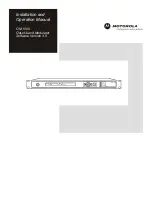
Motorola OM 1000, Installation And Operation Manual
The Motorola OM 1000 is a powerful and reliable device designed to enhance communication in various industries. Ensure seamless installation and operation with our comprehensive "Installation And Operation Manual". Download the manual for free from our website and unlock the full potential of your Motorola OM 1000.
Share
Download


Reviews:
No comments
Related manuals for OM 1000
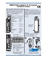
BM450
Brand: Naval Electronics AB Pages: 2
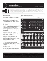
Maestro
Brand: acid rain technology Pages: 2
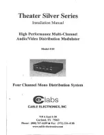
4101
Brand: Cable Electronics Pages: 8

MD-4
Brand: T2 Pages: 7

MD-EM1
Brand: T2 Pages: 7
TQM 1616
Brand: Teknoline Pages: 23
CTARM-2SV
Brand: CableTronix Pages: 4
HDDM
Brand: Toner Pages: 22
GRB-200
Brand: Quorum Pages: 54
XP300
Brand: DigiTech Pages: 4

TWIN PEAKS V5
Brand: Drolo Pages: 4
XP400
Brand: DigiTech Pages: 4
Agile 2020
Brand: Wavecom Pages: 20

UIM 1-00
Brand: axing Pages: 40
CT-FSAM550
Brand: CableTronix Pages: 10
NOVA Modulator NM-1
Brand: TC Electronic Pages: 34

CT-FMM
Brand: CableTronix Pages: 8
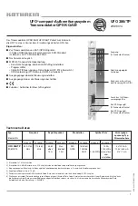
20610014
Brand: Kathrein Pages: 64


