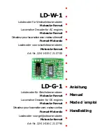
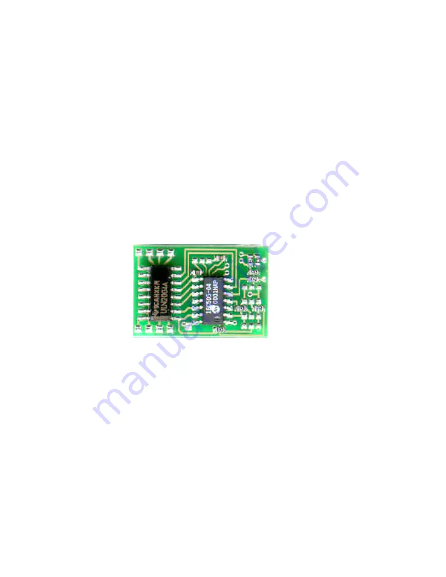
background image

n

LD-W-1

n

Lokdecoder für Wechselstrommotoren

Motorola-Format

n

Locomotive Decoder for AC engines

Motorola-Format

n

Décodeur pour locomotive avec moteur alternatif

Format-Motorola

n

Locdecoder voor wisselstroommotoren

Motorola-format

n

Art.-Nr. 22-01-015 C 21 27 00

n

n

n

n

LD-G-1

n

Anleitung

Lokdecoder für Gleichstrommotoren

Motorola-Format

n

Manual

Locomotive Decoder for DC engines

Motorola-Format

n

Mode d´emploi

Décodeur pour locomotive avec moteur continu

Format-Motorola

n

Handleiding

Locdecoder voor gelijkstroommotoren

Motorola-format

n

Art.-Nr. 22-01-016 C 21 27 96

n

Summary of Contents for LD-G-1

Page 1: ...ecoder voor wisselstroommotoren Motorola format n Art Nr 22 01 015 C 21 27 00 n n n n LD G 1 n Anleitung Lokdecoder für Gleichstrommotoren Motorola Format n Manual Locomotive Decoder for DC engines Motorola Format n Mode d emploi Décodeur pour locomotive avec moteur continu Format Motorola n Handleiding Locdecoder voor gelijkstroommotoren Motorola format n Art Nr 22 01 016 C 21 27 96 n ...

Page 2: ...r by any means electronic or mechanical including photocopying without prior permission in writing from Tams Elektronik GmbH Subject to technical modification 07 2002 Tams Elektronik GmbH Tout droits réservés en particulier les droits de reproduction et de diffusion ainsi que le traduction Toute duplication ou reproduction sous quelque forme que ce soit nécessite l accord écrit de la societé Tams ...

Page 3: ...bles 27 Safe and correct soldering 27 Performing a visual check 28 Mounting the locomotive decoder 28 Setting the locomotive decoder 30 Operation 32 FAQ 33 Manufacturer s note 34 Certification 34 Conditional warranty 34 Diagram Setting the locomotive address 68 Circuit Diagram LD G 1 Fig 1 I Circuit Diagram LD W 1 Fig 2 II Connections 1 front LD G 1 and LD W 1 Fig 3a and 3b III Connections 2 rear ...

Page 4: ...cuits are very sensitive to static electricity Do not touch components without first discharging yourself Touching a radiator or other grounded metal part will discharge you The module can be used according to the specifications of this manual It is designed for the mounting in a model railway locomotive with d c motor LD G 1 resp a c motor LD W 1 It evaluates the Motorola format data sent by the ...

Page 5: ...high humidity Condensation building up can cause serious injury due to electrical shock Take the following precautions to prevent this danger Never perform wiring on a powered module Only use low power for this module as described in this manual and only use certified transformers Connect transformers and soldering stations only in approved mains sockets installed by an authorised electrician Obse...

Page 6: ... remove liquid solder with a thick wet rag or wet sponge Dangerous environments A working area that is too small or cramped is unsuitable and can cause accidents fires and injury Prevent this by working in a clean dry room with enough freedom of movement Other dangers Children can cause any of the accidents mentioned above because they are inattentive and not responsible enough Children under the ...

Page 7: ...format The digital driving data is differently encoded and transmitted in the old Motorola I format and the new Motorola II format The locomotive decoder is designed to evaluate data in Motorola II format This limits its use in Motorola I format Since data of the auxiliary functions F1 to F4 sent in Motorola I Format cannot be evaluated by the locomotive decoder it is not possible to switch these ...

Page 8: ...an be fixed Compared to the set standard velocity characteristic this characteristic allows a higher maximum speed however the shunting gear is no longer available Acceleration and brake delay Three variants of acceleration and brake delay are available fast medium and slow By attaching solder bridges one of the three variants can be fixed Function lighting The lighting can be switched on and off ...

Page 9: ...ctions F1 to F4 are not available in Motorola I format It is possible to control one accessory via the function function according to the direction of travel Technical specifications Data format Motorola I and II Supply voltage 12 22 Volt digital voltage Current consumption without connected loads ca 10 mA Max current for motor 1 000 mA Max current per function output 500 mA Max total current 1 50...

Page 10: ...opper tracks Only use tin solder SN 60 Pb i e 60 tin 40 lead with rosin based flux Solder fast long soldering can destroy components and copper tracks and damages through plated holes Use a small soldering iron with max 30 Watt Keep the soldering tip clean so the heat of the soldering iron is applied to the solder point effectively Apply the soldering tip to the soldering spot in such a way that t...

Page 11: ...reme interference Connecting the LD G 1 Follow the connections diagrams fig 4 Solder the connections to the rails at points X1 and X2 rear of the decoder and the connections to the motor at the points X11 and X12 rear of the decoder The connection to the rails is optional but you must observe polarity when connecting the motor Connecting the LD W 1 Follow the connections diagrams fig 5 Solder the ...

Page 12: ...mps often flicker in operation You can avoid the flickering of the lamps if you connect the second side to the return conductor point X3 instead of locomotive ground Caution If you connect the loads to the return conductor for all functions point X3 the load must be insulated The loads must not make contact with metal parts of the locomotive Possible short circuit The locomotive decoder will be da...

Page 13: ...for example Using an NEM 652 interface connector Contact Connection Colour of cable Connecting points 1 Motor connection 1 orange X11 2 Lighting back yellow X5 3 Not used or F1 green X7 4 Power supply left black X1 5 Motor connection 2 grey X12 6 Lighting front white X4 7 Common conductor for all functions blue X3 8 Power supply right red X2 Some locomotives already have an NEM 652 interface conne...

Page 14: ...nting gear active switched via F4 X17 Pin 1 X 20 Second velocity characteristic shunting gear inactive X17 Pin 1 X 17 Pin 2 Standard velocity characteristic shunting gear inactive X17 Pin 3 no solder bridge Fast delay X17 Pin 3 X 20 Slow delay X17 Pin 3 X 17 Pin 2 Medium delay Example Adjusting the second velocity characteristic and the medium acceleration and brake delay Setting the locomotive ad...

Page 15: ...is used for switching the shunting gear When activated the aproach and braking delays are automatically deactivated The other accessories connected to the output X10 will also switch with the shunting gear Improvement of the driving characteristics Locomotives with especially high current consumption or track sections with bad contacts e g some types of points may give an unsatisfactory performanc...

Page 16: ...1 and X12 have been exchanged à Exchange the connections A lamp flickers this is not a defect Possible cause The lamp is connected with one side to locomotive ground à If you do not want the lamp to flicker disconnect it from locomotive ground insulate it and connect it to the return conductor point X3 The locomotive does not run Possible cause The locomotive address is not set correctly à Check t...

Page 17: ...improvements supply spare parts or return the purchase price The following invalidate the warranty using an unsuitable soldering iron solder containing liquid acids or similar if damage is caused by not following the instructions in this manual or the circuit diagram if the circuit has been altered and repair attempts have failed if arbitrary changes in the circuit are made if parts are stored inc...

Page 18: ...s X14 X16 X15 X13 1 2 3 2 3 2 4 2 4 21 2 3 1 2 1 2 2 4 2 2 3 2 4 2 4 2 4 22 2 3 2 4 1 2 3 2 4 1 2 23 2 3 1 2 2 4 2 4 4 2 3 2 3 2 4 1 2 24 2 4 2 4 2 4 1 2 5 1 2 1 2 2 4 1 2 25 2 3 1 2 2 4 1 2 6 2 4 2 4 1 2 26 2 3 1 2 2 4 7 1 2 2 4 1 2 27 2 4 2 4 1 2 1 2 8 2 3 2 4 2 3 2 4 28 2 3 2 3 1 2 1 2 9 1 2 1 2 2 4 2 4 29 2 3 2 4 1 2 1 2 10 2 4 2 4 30 1 2 1 2 11 1 2 2 4 2 4 31 2 4 1 2 12 2 4 2 4 32 1 2 1 2 1 2...

Page 19: ...1 2 1 2 87 1 2 2 3 2 4 2 3 52 2 3 2 4 2 4 88 2 3 1 2 1 2 53 1 2 2 3 1 2 89 2 4 2 4 2 4 54 2 4 2 4 1 2 2 4 90 2 4 2 3 2 4 55 2 3 2 3 1 2 2 4 91 2 4 2 4 2 3 56 2 3 2 4 1 2 2 4 92 2 4 2 3 2 3 57 2 3 2 4 2 4 93 1 2 2 4 2 4 58 2 3 1 2 1 2 2 3 94 1 2 2 3 2 4 59 1 2 1 2 2 3 95 1 2 2 4 2 3 60 1 2 2 4 96 1 2 2 3 2 3 61 2 4 2 4 97 2 4 2 3 1 2 2 4 62 2 3 1 2 2 4 98 2 4 2 3 2 4 63 1 2 1 2 1 2 2 4 99 2 4 2 3 1...

Page 20: ... 3 1 2 122 2 4 2 3 1 2 158 2 3 2 4 1 2 123 1 2 1 2 159 2 4 2 4 1 2 124 2 4 2 3 160 2 3 125 1 2 2 4 1 2 161 2 3 2 3 2 4 2 3 126 1 2 2 3 1 2 162 2 3 2 4 2 3 127 1 2 2 4 163 2 3 2 4 2 3 128 1 2 2 3 164 2 4 2 3 129 2 4 2 3 1 2 1 2 165 2 3 2 3 1 2 2 3 130 2 4 2 3 1 2 166 131 2 4 2 3 1 2 167 1 2 1 2 2 3 132 2 4 2 3 168 1 2 133 1 2 2 3 1 2 1 2 169 1 2 2 3 134 1 2 2 3 1 2 170 2 4 135 2 4 1 2 171 1 2 2 4 1...

Page 21: ... 2 2 3 2 4 232 2 4 2 4 2 3 197 2 3 1 2 233 2 3 2 3 2 3 198 2 4 2 3 2 4 234 2 3 2 4 2 3 199 2 3 2 3 2 3 235 2 4 2 4 2 3 1 2 200 1 2 2 3 2 3 2 3 236 2 3 2 3 2 3 1 2 201 2 4 2 3 2 3 237 2 3 2 4 2 3 1 2 202 1 2 2 4 2 3 2 3 238 2 3 2 4 2 3 2 3 203 2 3 2 3 2 4 239 2 4 2 4 2 3 2 3 204 1 2 2 3 2 3 2 4 240 2 3 2 3 2 3 2 4 205 2 4 1 2 2 3 2 3 241 1 2 1 2 2 3 206 2 4 1 2 2 3 242 2 3 207 2 4 1 2 2 3 243 1 2 2...

Page 22: ...LD G 1 LD G 1 Seite Page Page Pagina I Seite Page Page Pagina I LD G 1 Schaltplan Circuit diagram Schéma de principe Schakelschema n n n Fig 1 Ausgänge Outputs Sorties Uitgangen ...

Page 23: ...LD W 1 LD W 1 Seite Page Page Pagina II Seite Page Page Pagina II LD W 1 Schaltplan Circuit diagram Schéma de principe Schakelschema n n n Fig 2 Ausgänge Outputs Sorties Uitgangen ...

Page 24: ...LD G 1 LD W 1 LD G 1 LD W 1 Seite Page Page Pagina III Seite Page Page Pagina III Anschlußplan 1 Connections 1 Plan de raccordement 1 Aansluit plan 1 n n n Fig 3a 3b ...

Page 25: ...LD G 1 LD W 1 LD G 1 LD W 1 Seite Page Page Pagina IV Seite Page Page Pagina IV Anschlußplan 2 Connections 2 Plan de raccordement 2 Aansluit plan 2 n n n Fig 4 5 ...

Page 26: ... Actuele informatie en tips n http www tams online de n n n n Garantie und Service Warranty and service n Garantie et service Garantie en service n Tams Elektronik GmbH Sievertstraße 22 D 30625 Hannover fon 0049 0 511 55 60 60 fax 0049 0 511 55 61 61 n e mail modellbahn tams online de n ...

Reviews: