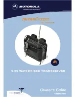

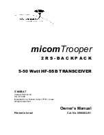


Summary of Contents for HF-SSB
Page 1: ......
Page 2: ......
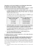
Page 6: ......
Page 8: ......
Page 18: ...Intentionally Left Blank iv ...
Page 26: ...Intentionally Left Blank 1 8 ...
Page 33: ...Lower Battery Flap Upper Battery Flap Battery Straps 2 7 ...
Page 35: ...Battery Connector Power Cable Power Connector Transceiver 2 9 ...
Page 37: ...2 11 ...
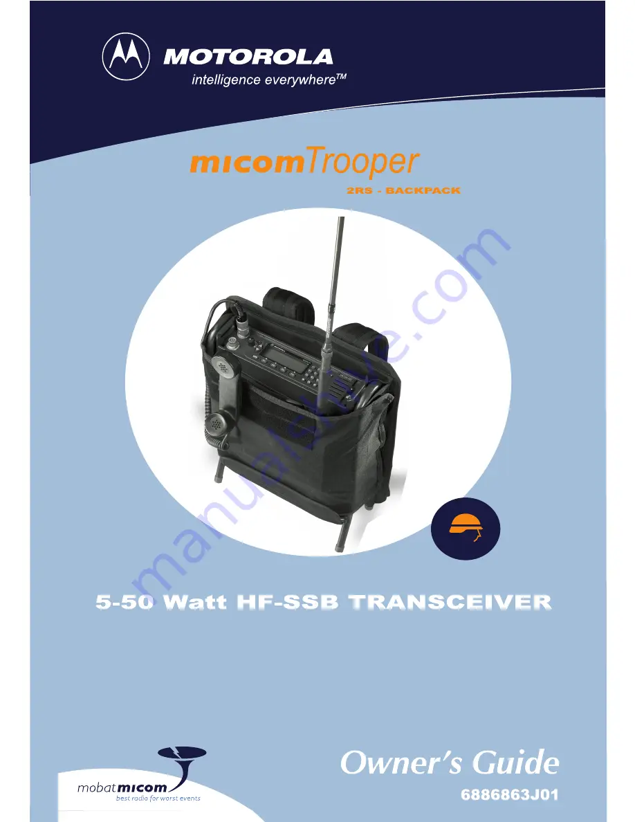
Page 39: ...Whip Mount Antenna Base Whip Antenna Handset 2 13 ...
Page 42: ...Intentionally Left Blank 2 16 ...
Page 48: ...Intentionally Left Blank 3 6 ...
Page 52: ...Intentionally Left Blank A 4 ...
Page 56: ...Intentionally Left Blank B 4 ...


