Motorola HF-SSB T1961A, Installation Procedures Manual
The Motorola HF-SSB T1961A is a high-performance communication device that offers reliable and efficient long-range transmission capabilities. Ensure seamless setup and operation with the comprehensive Installation Procedures Manual. Download this essential manual for free, exclusively from our website, and unlock the full potential of your Motorola HF-SSB T1961A.
Share
Download


Reviews:
No comments
Related manuals for HF-SSB T1961A
CT20
Brand: Samson Pages: 2
LU20
Brand: Ibanez Pages: 2
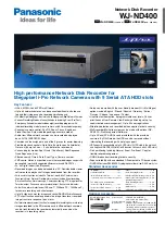
WJND400 - NETWORK DISK RECORDER
Brand: Panasonic Pages: 2

WJ-NX200K
Brand: i-PRO Pages: 22
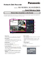
WJ-NV300K
Brand: Panasonic Pages: 4

WJ-NX400K
Brand: Panasonic Pages: 30
TS-108
Brand: B&K Pages: 5
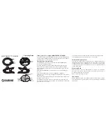
Odyssey
Brand: SABINE Pages: 2
M4 Series
Brand: DaySequerra Pages: 16
T-103
Brand: Accuphase Pages: 13
312C
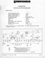
Brand: H.H. Scott Pages: 8
340B
Brand: H.H. Scott Pages: 23
62789
Brand: Hama Pages: 40

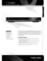
T-403
Brand: Harman Kardon Pages: 5
TU 980
Brand: Harman Kardon Pages: 2

PT2500
Brand: Harman Kardon Pages: 16
CITATION 23
Brand: Harman Kardon Pages: 12

TU915
Brand: Harman Kardon Pages: 9


