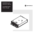


Installation and
Operation Manual
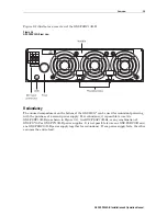
GX2-PSDC10D-R
Power Supply
S
E
U
F
SE
U
F
SE
U
F
W A
RR
AN
TY
VO
ID
S
RO
IF
EA
LB
KE
N
C
UT
A
ION
C
DIS
CON
NE
T P
OW
ER
BEF
ORE
REM
OVIN
G
U
IT
R
M
N
F
O
S
CHA
S
IS
5
8841-00
-00 CODE: 1
2
2
G
R
O
ER
X2-PSDC10D-
P
W
SUPPL
Y
07
P
60
0
00
2
D
A
6
4
0
0
9
F918B
000Q
E
O
E
X
SD
0
M
D
L:
G
2-P
C1
D-
R
X
AIH
-G
2-D
C
PR
OD
CT
P
L
PIN
S
U
OF
HI
IP
E
,
INPUT
: 36-75V
14.8-7
.1A
OUTPUT
:
V
16
A M
X.
12
.1
A
5
. A
MAX
.1V
17
9
.
3.7V
19.2A MAX.
A
0
M
X. POWER:
3 0W
Summary of Contents for GX2-PSDC10D-R
Page 13: ......
Page 17: ......
Page 19: ......
Page 23: ......
Page 24: ...512823 001 a 9 07 Visit our website at www motorola com ...


