background image

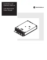
Installation and 
Operation Manual

GX2-PSAC10D-R
Power Supply

U

SE

 O

N

LY

 W

IT

H

 25

0V

 FU

SE

S

1 0

52884

- 01-00

GX2

PSAC1

0D-R Power Supply

-

E06AP

6

3

C

6

0

00

00

00

6

E9

69X000C

W A

RR

AN

TY

VO

ID

S

RO

IF

EA

LB

KE

N

MO

DE

L

X2

-P

SAC

1

D-

R

: G

0

AIH

-G

2

X

M

X

P

WE

300

A

. O

R:

W

1

A

3.7V

9.2

MAX

.

1 V

1 .1

AM

X.

2

6

A

5.1

17

A

V

.9

MAX

.

PU

5/ 3

V~

IN

T: 11

2 0

50 6

0 H

4.5

2 3A

/

z

/ .

U

P

T:

O

T

U

PR

DU

CT

OF

P

I IP

PIN

ES

O

H L

E18624

9

R

C

UT

A

ION

C

DIS

CON

NE

T P

OW

ER

BEF

ORE

 REM

OVIN

G

U

IT

R

M

N

 F

O

S

CHA

S

IS

Summary of Contents for GX2-PSAC10D-R

Page 1: ...A P 6 3 C 6 0 0 0 0 0 0 0 6 E9 69 X0 00 C W A R R A N T Y V O ID S R O IF E A L B K E N MODEL X2 P SAC1 D R G 0 AIH G 2 X M X P WE 300 A O R W 1 A 3 7V 9 2 MAX 1 V 1 1AM X 2 6 A 5 1 17 A V 9 MAX PU 5 3 V IN T 11 2 0 50 60 H 4 5 2 3A z U P T O T U PR DUCT OF P I IPPINES O H L E1 86 24 9 R C UT A ION C DISCONNE T POWER BEFORE REMOVING U IT R M N F O S CHAS IS ...

Page 2: ...having the same electrical ratings marked at the location of the fuse This symbol indicates a hot surface Use caution before touching a surface marked with this symbol This equipment operates over the marked Voltage and Frequency range without requiring manual setting of any selector switches Different types of line cord sets may be used for connections to the mains supply circuit and should compl...

Page 3: ...lowing standards EMC Standards EN55022 EN55024 EN55013 EN50083 2 CISPR 22 CISPR 24 CISPR 13 IEC60065 Safety Standards EN60065 EN60825 EN50083 1 EN60950 IEC 60950 A1 1992 A2 1993 A3 1995 A4 1996 following the provisions of the Directive s of the Council of the European Union EMC Directive 89 336 EEC Low Voltage Directive 73 23 EEC WARNING There is an energy hazard on this built in power supply Duri...

Page 4: ...3 Calling for Repairs 1 4 Section 2 Overview Redundancy 2 3 Section 3 Installation and Operation Unpacking 3 1 Installation 3 1 Powering 3 2 Operation 3 2 Fault Reporting 3 3 Appendix A Specifications Input Power A 1 Output Power A 1 Physical Properties A 1 Environmental A 1 Appendix B Menus Module Status Menu B 1 Module Info Menu B 2 Alarms B 2 Abbreviations and Acronyms ...

Page 5: ...fully populated 2 1 Figure 2 2 GX2 PSAC10D R front view 2 2 Figure 2 3 GX2 PSAC10D R top view 2 2 Figure 2 4 GX2 PSAC10D R rear view 2 3 Figure 3 1 GX2 PSAC10D R 3 1 Figure 3 2 AC input connector 3 2 Figure 3 3 GX2 PSAC10D R block diagram 3 2 Tables Table 3 1 LED fault indication 3 3 Table B 1 GX2 PSAC10D R menus B 1 ...

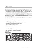
Page 6: ...th applications optimize operating space Its high module density enables network operators to install more equipment in less space The wide operational bandwidth of the platform enables you to offer more revenue generating services This manual describes the GX2 PSAC10D R power supply that provides power for the equipment shelf GX2 HSG and all application modules The GX2 PSAC10D R features include ...

Page 7: ...anual Related Documentation The following documents provide information that is required for products that can be used with the GX2 PSAC10D R GX2 CM100B Control Module Installation and Operation Manual GX2 PSDC10D R DC Power Supply Installation and Operation Manual GX2 HSG Equipment Shelf Installation Manual There are additional documents that provide information that may be of interest to you The...

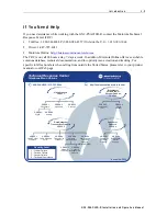
Page 8: ... manual or our Web page http businessonline motorola com Data Networks Transmission Products PRESS 3 Products PRESS 1 Cable Router VOIP PRESS 2 Cable Modems Products PRESS 3 Transmission Transport Products MBT MWT MEA PRESS 5 Multiservice Management PRESS 4 Network Licensing PRESS 1 Network Management Products PRESS 2 Network Technical Response Center Telephone Menu Options Connected Home Solution...

Page 9: ...s The Repair Facility is open from 8 00 AM to 5 00 PM Central Time Monday through Friday When calling from outside the United States use the appropriate international access code and then call 956 541 0600 to contact the Repair Facility When shipping equipment for repair follow these steps 1 Pack the unit securely 2 Enclose a note describing the exact problem 3 Enclose a copy of the invoice that v...

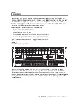
Page 10: ...clude Equipment shelf model GX2 HSG Control module GX2 CM100B Power supply module GX2 PSAC10D R or GX2 PSDC10D R A series of application modules to fit any system requirement Figure 2 1 illustrates a front view of a fully populated GX2 HSG Figure 2 1 GX2 HSG fully populated The GX2 PSAC10D R provides 5 1 12 and 3 7 VDC power to the GX2 HSG and all application modules The auto sensing input voltage...

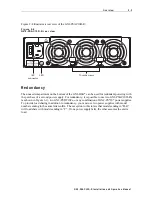
Page 11: ... Figure 2 2 illustrates a front view of the GX2 PSAC10D R Figure 2 2 GX2 PSAC10D R front view Figure 2 3 illustrates a top view of the GX2 PSAC10D R Figure 2 3 GX2 PSAC10D R top view CAUTION Surface may be hot Disconnect power and allow surface to cool before touching ...

Page 12: ...ering with the purchase of a second power supply For redundancy it is possible to use two GX2 PSAC10D R s as shown in Figure 3 1 two GX2 PSDC10Cs or any combination of GX2 PS 10 power supplies To provide load sharing in addition to redundancy you must use two power supplies with model numbers ending in the same letter suffix The exception to this rule is that models ending in D R will load share w...

Page 13: ...llation To operate the GX2 HSG must be equipped with a GX2 PSAC10D R or GX2 PSDC10D R power supply To install the GX2 PSAC10D R power supply 1 Rotate the power supply so that the cooling fans face you and the external power connection is on the left 2 Position the power supply into the left or right side power supply compartment on the rear of the GX2 HSG as illustrated in Figure 3 1 Figure 3 1 GX...

Page 14: ...y five minutes before restoring power or the unit may not start properly In normal operation it is not necessary to remove power from the equipment shelf when installing a new module or replacing one The shelf and all modules are designed to enable module replacement with power applied Operation The AC input voltage which must be between 105 Vrms and 264 Vrms is filtered and then applied to a powe...

Page 15: ...required Not lit If the LED is not lit verify that system power is available The GX2 PSAC10D R also includes non volatile memory to store module identity information that includes model number serial number and manufacturing date code To access this information the GX2 CM100B Control Module must be installed in the GX2 HSG Data from the GX2 PSAC10D R is reported to the GX2 CM100B and is accessible...

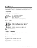
Page 16: ... slow blow at power input connector Output Power Output voltage 5 1 VDC range 12 VDC range 3 7 VDC range 5 05 to 5 15 VDC nominal with maximum load at 25 C 11 88 to 12 12 VDC nominal with maximum load at 25 C 3 66 to 3 75 VDC nominal with maximum load at 25 C Output current 5 1 VDC range 12 VDC range 3 7 VDC range Maximum total output power 17 9 amps maximum with maximum load at 25 C 16 1 amps max...

Page 17: ...rom the top level PS1 or PS2 menu Press the right arrow Then press the up and down arrows to scroll to the MODULE STATUS MENU or the MODULE INFO MENU Change a parameter value Press the right arrow to enter edit mode Use the up and down arrows to change the value Press ENTER to save the new value or press the left arrow to exit edit mode without changing the value If you press no key for 10 to 15 s...

Page 18: ...yyyy FW REV XX HW REV XX Alarms The second line on the SDU can display any of the following messages when an alarm condition exists FAN CURRENT ALARM 12V BACKPLANE ALARM 5 1V BACKPLANE ALARM 3 7V BACKPLANE ALARM AMBIENT TEMPERATURE ALARM HEATSINK TEMPERATURE ALARM BANK 0 BOOT ALARM BANK 1 BOOT ALARM FLASH ALARM FACTORY CRC ALARM ALARM CRC ALARM MODEL NAME ALARM POWER SUPPLY FAIL ...

Page 19: ... this manual CATV Community Antenna Television dB decibels dBm decibels referenced to one milliwatt dBc decibels relative to carrier level dBmV decibels referenced to one millivolt ESD electrostatic discharge LED light emitting diode MHz Megahertz mW milliwatts RF radio frequency RSA Return for Service Authorization TRC Technical Response Center TTR time to repair ...

Page 20: ...538445 001 a 5 07 Visit our website at www motorola com ...

Reviews: