


Summary of Contents for F2265A
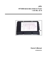
Page 1: ...ATU HF SSB Automatic Antenna Tuner 1 6 30 MHz 125 W Owner s Manual 68P02948C35 A ...
Page 2: ......
Page 3: ...ATU HF SSB Automatic Antenna Tuner 1 6 30 MHz 125 W Owner s Manual 68P02948C35 A ...
Page 4: ......
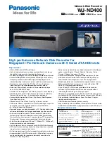
Page 10: ......
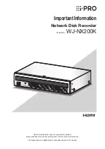
Page 12: ......