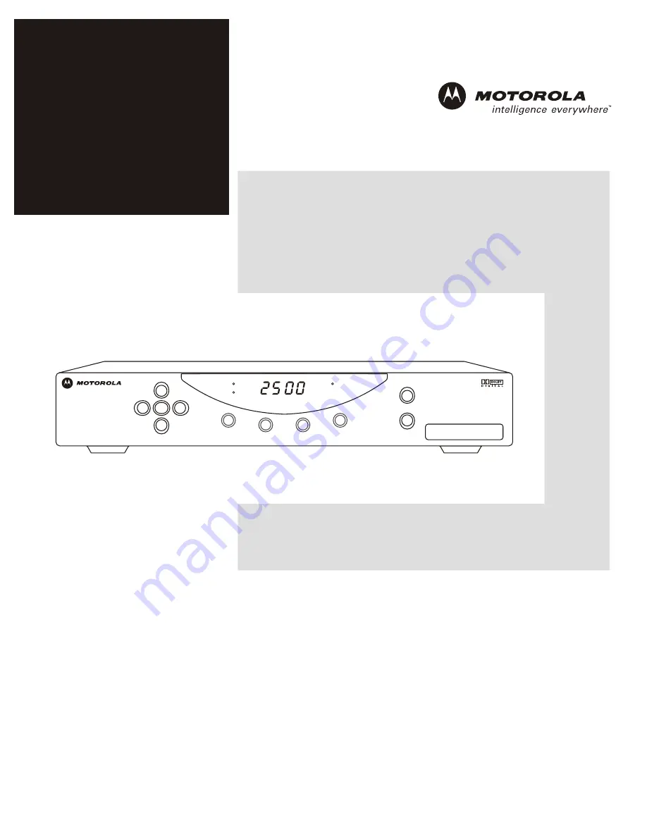
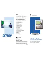
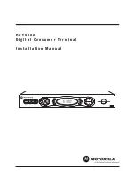
Motorola DCT2500, Installation Manual
The Motorola DCT2500 User Manual is an essential companion for users of this innovative product. Packed with valuable information and guidance, this manual can be downloaded for free from our website, ensuring that users can optimize their device's features and capabilities. Get ready to explore the full potential of your Motorola DCT2500! (Note: Website name is not provided in the prompt)
Share
Download


Reviews:
No comments
Related manuals for DCT2500
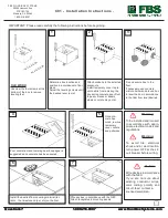
C01
Brand: FBS Pages: 2
C-BOX 100
Brand: Datalogic Pages: 25
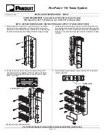
PN79G
Brand: Panduit Pages: 2
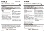
Robus REX4P0-01
Brand: LED Group Pages: 3
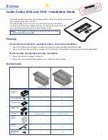
Cable Cubby 1202
Brand: Extron electronics Pages: 8
DCT 6208
Brand: Seaside Communications Pages: 48
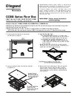
CCBBS
Brand: LEGRAND Pages: 4
Cable Box
Brand: Sony Pages: 48
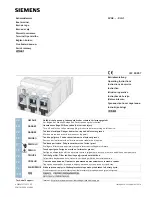
3VA9-0JA1 Series
Brand: Siemens Pages: 4
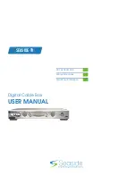
DCT2500
Brand: Motorola Pages: 54
DCT5100
Brand: Motorola Pages: 2
DCT5100
Brand: Motorola Pages: 81
NDA-31135
Brand: NEC Pages: 38
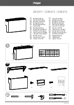
ZAX011
Brand: hager Pages: 2
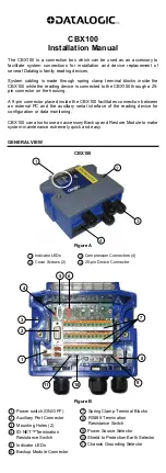
CBX100
Brand: Datalogic Pages: 8

Defender Series
Brand: Adam Hall Pages: 100

Defender Compact
Brand: Adam Hall Pages: 56
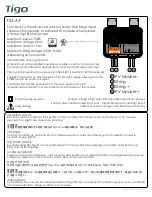
TS4-A-F
Brand: Tigo Pages: 2


