background image

D C P 5 0 1

H o m e T h e a t e r S y s t e m

I n s t a l l a t i o n M a n u a l

D C P 5 0 0 S e r i e s

Summary of Contents for DCP501 - DVD Player / AV Receiver

Page 1: ...D C P 5 0 1 H o m e T h e a t e r S y s t e m I n s t a l l a t i o n M a n u a l D C P 5 0 0 S e r i e s ...

Page 2: ...teral triangle is intended to alert the user to the presence of important installation servicing and operating instructions in the documents accompanying the equipment For continued protection against fire replace all fuses only with fuses having the same electrical ratings marked at the location of the fuse WARNING TO PREVENT FIRE OR SHOCK HAZARD DO NOT EXPOSE THIS APPLIANCE TO RAIN OR MOISTURE T...

Page 3: ...ed continue to reflect the equipment being produced can be expected to be within the variation accepted due to quantity production and testing on a statistical basis as required by 47 CFR 2 909 Operation is subject to the following condition This device must accept any interference received including interference that may cause undesired operation The above named party is responsible for ensuring ...

Page 4: ...7 0450 for a Return for Service Authorization RSA number before sending the unit The RSA number must be prominently displayed on all equipment cartons Pack the unit securely enclose a note describing the exact problem and a copy of the invoice that verifies the warranty status Ship the unit PRE PAID to the following address Motorola Inc C O UPS Freight Service Attn RSA ___________ 1201 C Street NW...

Page 5: ... 4 Storing Discs 2 4 Region Numbers 2 4 Front Panel 2 5 DCP501 Display 2 8 Rear Panel 2 11 Operating the Remote Control 2 14 Selecting TV and VCR Setup Codes 2 18 Verifying a Setup Code Using Blink Back 2 18 Finding a Setup Code 2 19 Installing Batteries in Remote Control 2 20 Section 3 Installation 3 1 Before You Begin 3 2 Installing the DCP501 3 2 Recording Your Connections 3 3 Connecting a TV 3...

Page 6: ...Antennas 3 20 Connecting for Power 3 21 Connecting to the Front Panel 3 21 A B IN Module Cabling Optional 3 23 Telephone Modem 3 24 Operational Check 3 25 Section 4 Operation 4 1 Before You Begin 4 1 Setting Up Audio 4 2 Input Setup 4 2 Subwoofer and Speakers 4 5 Test Tone Adjust 4 18 Advanced Audio Setup 4 23 Using DCP501 Cable TV Functions 4 30 Using Cable TV Record 4 30 Using CATV Channel Scan ...

Page 7: ... Edit on a DVD 4 46 Insert Chapter on a DVD 4 47 Delete Program on a DVD 4 47 Exiting Program Play on a DVD 4 47 Using the Repeat Feature 4 48 Repeat Play 4 48 A B Repeat Play 4 48 Using the CD Banner Display 4 49 Selecting a CD Track 4 49 Using IntroScan on a CD 4 49 Using Bookmarks on a CD 4 50 Recalling a Bookmarked Selection on a CD 4 50 Clearing a Bookmark on a CD 4 50 Program Edit on a CD 4 ...

Page 8: ...me Up Down 4 66 DVD CD Playback Control 4 66 Source Change 4 67 Section 5 Troubleshooting 5 1 Appendix A Specifications A 1 Digital Cable Receiver A 1 A V Receiver and Amplifier A 1 DVD CD Player A 2 Input Output A 2 Front Panel Inputs A 2 Front Panel Outputs A 2 Rear Panel Inputs A 2 Rear Panel Outputs A 3 General A 3 Appendix B TV and VCR Setup Codes B 1 TV Setup Codes B 1 VCR Setup Codes B 5 Ap...

Page 9: ...tes D 17 Purchasable Indicator LED and OSD D 17 Preview Indicator LED and OSD D 18 CURRENT CHANNEL STATUS OSD D 18 Current channel status OSD fields D 20 D 08 Renewable Security System D 21 TvPC Required LED and OSD D 22 Current Mode D 22 TvPC Status D 22 D 09 Upstream Modem Status D 23 STARVUE II RF Diagnostics D 23 STARFONE Diagnostics D 25 D 10 Application Code Modules D 31 D 11 Memory Status D...

Page 10: ...re 3 2 S video connections to a TV 3 4 Figure 3 3 Composite video connections to a TV 3 5 Figure 3 4 Connecting to cable TV 3 6 Figure 3 5 Example of speaker placement 3 7 Figure 3 6 Connecting front speakers and active subwoofer 3 9 Figure 3 7 Connecting front speakers and passive subwoofer 3 10 Figure 3 8 Connecting surround and center speakers 3 11 Figure 3 9 S video connections to a VCR 3 13 F...

Page 11: ...ANNEL STATUS OSD for digital channel D 19 Figure D 15 Renewable security status LEDs D 21 Figure D 16 RENEWABLE SECURITY OSD D 21 Figure D 17 STARVUE II diagnostics LEDs D 23 Figure D 18 STARVUE II DIAGNOSTICS OSD D 23 Figure D 19 STARFONE diagnostics LEDs D 25 Figure D 20 STARFONE diagnostic screen D 25 Figure D 21 STARFONE Poll History screen D 27 Figure D 22 Application code module LEDs D 31 Fi...

Page 12: ...D 13 Purchasable status LED and OSD D 17 Table D 14 Preview status LED and OSD D 18 Table D 15 Current channel status OSD fields D 20 Table D 16 TvPC required D 22 Table D 17 Current mode D 22 Table D 18 TvPC status D 22 Table D 19 STARVUE II transmitter status D 24 Table D 20 STARVUE II IPPV status D 24 Table D 21 STARFONE diagnostic screen variables D 26 Table D 22 Poll history screen variables ...

Page 13: ... pay per view movie and events channels and Internet access It also enables the subscriber to connect their TV VCR speakers and other electronic devices through the DCP for easier control of their audio and video electronics The DCP501 is shown in Figure 1 1 Figure 1 1 DCP501 POWER AUDIO MODE SET UP CURSOR VOLUME TONE LEVEL MENU AM FM GUIDE FM MODE INFO TUNE CH PRESETS PHONES PLAY PAUSE SKIP SEARC...

Page 14: ...s how to install the IR Blaster Abbreviations and Acronyms The Abbreviations and Acronyms list contains the full spelling of the short forms used in this manual Document Conventions The following conventions are used in this manual Bold type Indicates text that you must type exactly as it appears or indicates a default value SMALL CAPS Denotes silk screening on the equipment typically representing...

Page 15: ...ing for Returns Credit If returns are necessary call the Motorola Customer Support Center at 1 866 MOT BCS1 1 866 668 2271 for a Return for Service Authorization RSA number before sending the unit The RSA number must be prominently displayed on all equipment cartons When shipping equipment for repair follow these steps 1 Pack the unit securely 2 Enclose a note describing the exact problem 3 Enclos...

Page 16: ...ious controls and displays Information on installing the DCP501 is provided in the Section 3 Installation NOTE When not in use turn off the DCP501 Features The DCP 501 includes DVD CD player single disc tray Audio Video Receiver AM FM tuner audio amplifier DCT2000 Digital Cable receiver analog digital hybrid Audio output 5 x 100 watts per channel Tripath Class T solid state amplifiers Dolby Digita...

Page 17: ... Video TV features include Tuning and watching either digital or analog cable TV channels on the cable system Viewing digital programs and movies played on the DCP501 DVD player Viewing analog programs and movies played on an analog VCR or analog video camera Viewing digital movies played on a digital VCR or digital video camera Viewing movies and programs recorded with a personal video recorder P...

Page 18: ...at can be used with the DCP501 and how to handle clean and store them Types of Discs You Can Use The DCP501 can play back the following discs Type Disc Logo Mark Contents Disc Size Maximum Playback Time 12 cm Approx 4 hours for a single sided disc or 8 hours for a double sided disc DVD Audio and Video 8 cm Approx 80 minutes for a single sided disc or 160 minutes for a double sided disc 12 cm Appro...

Page 19: ...nts such as record cleaning sprays to clean a disc Solvents can damage the disc Storing Discs When storing discs advise the subscriber to follow these guidelines Store discs vertically in their cases Do not stack or place objects on unprotected discs This can cause warping or scratches Do not store discs in direct sunlight or near a heat source Do not store discs in places subject to moisture or d...

Page 20: ... G I T A L S U R R O U N D 1 2 3 4 5 6 7 8 9 10 11 12 13 Item Control Description 1 CURSOR Moves cursor up down left right in DCP501 display on screen display and CATV application control 2 SELECT STORE Selects current DCP501 display on screen display item or CATV application controlled item 3 SET UP Press once to view DCP501 A V configuration menus Hold enter DCP501 diagnostics after 6 seconds Ex...

Page 21: ...AM FM MODE Press once to force FM station to mono Press again to return to normal TUNE Press to increase or decrease radio tuner frequency Hold to scan to next or previous strongest signal station 6 SOURCE Selects viewing source in the following sequence CATV DVD CD TUNER VCR1 VCR2 VIDEO1 VIDEO2 TAPE 7 VOLUME Increases clockwise or decreases counter clockwise pre amp and speaker level 8 POWER Plac...

Page 22: ...rent title track Press three times to repeat playback of current chapter DVD only Press again to clear the repeat function PROGRAM Press Once program DVD CD playback list On screen Press Twice program CD playlist on DCP501 display SHUFFLE Press Once shuffle current CD tracks Press Again clear shuffle SHUFFLE does not work with DVDs 13 VIDEO 2 Ports for connecting devices such as digital video came...

Page 23: ... on to indicate Dolby Pro Logic Surround is the currently selected audio mode 5 On indicates Dolby 3 Channel Stereo is the currently selected audio mode On indicates standard 2 Channel Stereo is the currently selected audio mode 6 Turns on when a DVD CD or external digital audio input is not Dolby or DTS audio 7 On indicates DSP sound mode is selected When DSP is selected the specific sound mode i...

Page 24: ... Chapter Repeat CD REPEAT turns on to indicate Disc Repeat and flashes TRACK to indicate Track Repeat 19 DVD CD turns on when a sequence for continuous play is being selected When a DVD or CD is in playback the A B button on the remote control can be used to select a sequence for continuous repeated play The A icon turns on to indicate the start of the sequence has been selected The B icon turns o...

Page 25: ...n on the remote control the following is displayed DVD Displays the current title of the DVD 30 After selecting DVD CD as the source and pressing DVD CD button on the remote control the following is displayed CD Displays the current track two digit number 31 After selecting DVD CD as the source and pressing DVD CD button on the remote control the following is displayed DVD displays the current cha...

Page 26: ...box behind the boxed icon indicates whether the speaker has been set up as LARGE the three dimensional box is turned on as shown in the example above or SMALL the three dimensional box is not turned on For more information on speaker settings see Initial Set up Operations in Section 4 Operations 37 On indicates Night mode enabled In Night mode you can set the DCP501 to dim the display illumination...

Page 27: ... digital audio output device with coaxial cable connector OPTICAL 1 digital audio input from digital audio output device with optical connector 10 Antenna FM 75 Ω Ω Ω Ω F connector used for FM antenna AM terminal tabs used for connecting AM antenna 11 Power Outlet AC power outlet 12 AUDIO IN VCR 1 left and right RCA jacks used for VCR audio output VCR 2 left and right RCA jacks used for audio outp...

Page 28: ...S video VCR 1 and VCR 2 connectors used for video output of VCR 1 and VCR 2 or PVR VIDEO 1 connectors used for video output of external video source such as a camcorder 16 VIDEO OUT The RCA jacks in the row labeled VIDEO are used for composite video The connectors in the row labeled S VIDEO are used for S video TV connectors used for video input of TV VCR 1 and VCR 2 connectors used for video inpu...

Page 29: ... DCP501 uses the DCP501 R Universal Remote Control Figure 2 5 illustrates the DCP501 R Universal Remote Control Figure 2 5 Remote control 1 24 25 26 29 31 32 33 34 35 36 38 39 40 41 42 43 44 46 45 47 48 49 37 27 30 28 2 3 4 5 6 7 8 9 10 11 12 13 14 15 16 17 18 19 20 21 22 23 ...

Page 30: ... button does not turn on Hold for more than six seconds enter DCP501 Diagnostics 9 GUIDE CATV application controlled 10 LAST CATV application controlled 11 VOL Raise or lower speaker level 12 MUTE Any DCP501 source mute speaker and pre amplifier outputs TV source mute speaker output 13 A CATV application controlled 14 B CATV application controlled 15 NIGHT Press once DIM mode DCP501 display dims a...

Page 31: ...uence playback 21 SHUFFLE CD source Press once shuffle current CD tracks 22 PROG Press Once program DVD CD playback list on screen display Press Twice program CD playlist on DCP501 display 23 CLEAR In playback clear A B Shuffle Repeat or Program playback modes and resume normal mode Not in playback clear A B Shuffle Repeat or Program playback modes 24 POWER Place DCP501 in standby mode Turns power...

Page 32: ...f DVD CD tray closed Close tray and begin playback if DVD CD tray open VCR 1 or VCR 2 source Begin playback 42 TUNE Cable TV source CATV application enabled DVD CD source Press once fast forward and play fast forward 1 Press twice fast forward and play fast forward 2 Press three times fast forward and play fast forward 3 Press four times fast forward and play fast forward 4 for DVD only Press agai...

Page 33: ... or VCR The setup code can be found in Appendix B TV and VCR Setup Codes When the setup code is accepted the selected mode button will blink three times If the setup code is not accepted or more than ten seconds have elapsed between button presses the selected mode button turns off the TV or VCR exits programming mode and the most recent pre programmed setup code is restored You can only set up th...

Page 34: ...s are listed by brand in Appendix B TV and VCR Setup Codes If the setup code for the subscriber s brand of TV or VCR is not listed or if their TV or VCR does not respond to the setup codes listed for its brand you can search for the setup code using the remote control s Step and Set function To search for a setup code 1 Press the mode button for the device either TV VCR 1 or VCR 2 for six seconds ...

Page 35: ...t up the remote control while in TV VCR 1 or VCR 2 mode Installing Batteries in Remote Control Before using the remote control you must install two AA 1 5 V alkaline batteries included as illustrated in Figure 2 6 To install batteries in the remote control 1 Press and slide the battery compartment cover off 2 Place the batteries in the compartment be careful to observe the correct polarity 3 Slide...

Page 36: ...es in accordance with all applicable laws rules and regulations Motorola will not be liable to anyone for the user s failure to use and or dispose of batteries in the proper manner and in accordance with such laws rules and regulations or for any defect contained in batteries that may cause injury damage to persons or property ...

Page 37: ...ing Connecting a TV Connecting to Cable TV Connecting speakers and subwoofer Connecting a VCR Video connections Audio connections Connecting other audio visual sources Digital audio connections Connecting a tape deck or an additional CD player Connecting the FM and AM antennas Connecting for power Connecting to the front panel Game console Digital camera Camcorder analog or digital MiniDisc player...

Page 38: ...onnection between the RF In and To RF In ports Removal of this cable could disrupt operation of the DCP501 WARNING To avoid damaging the DCP501 do not use the cable connection between the RF In and To RF ports as a handle Installing the DCP501 Before making any connections to the DCP501 refer to the diagrams later in this section for more detailed information CAUTION The DCP501 should be placed on...

Page 39: ...ect the subscriber s system if they move the equipment or add new equipment Figure 3 1 Recording your connections Front speakers Left Right Surround speakers Left Right Center speaker Subwoofer CABLE ANTENNA IN INPUT S VIDEO VIDEO AUDIO LEFT AUDIO RIGHT To TV CABLE ANTENNA IN OUTPUT AUDIO L R VIDEO INPUT AUDIO L R VIDEO VCR DCP501 TV S VIDEO S VIDEO MODEL NO DCP 501 À LA PLUIE NI À L HUM IDITE ...

Page 40: ...ilable on the DCP501 If the subscriber s TV does not provide S video use the VIDEO connections To determine whether the subscriber s TV features S video or composite video check the manual supplied with the TV to determine the best connection available S Video To connect the DCP501 to a TV with S video capability Figure 3 2 S video connections to a TV À LA PLUIE NI À L HUMIDITE MODEL NO DCP 501 DC...

Page 41: ... TV À LA PLUIE NI À L HUMIDITE MODEL NO DCP 501 DCP501 CABLE ANTENNA IN INPUT S VIDEO VIDEO AUDIO LEFT AUDIO RIGHT TV Video Cable s you will need When connecting the video path never connect composite video and S Video together Because certain types of electronics equipment will not support both video inputs simultaneously use only one connection path ...

Page 42: ...e Motorola DCP501 can be activated only in certain cable systems throughout North America In cable systems where that feature cannot be activated you may connect an external cable receiver provided by the local cable provider For best results connect an external cable receiver through the audio and video inputs on the back of the DCP501 CAUTION To avoid damaging the DCP501 do not use the cable con...

Page 43: ...d center speakers should be at the same height Position the front speakers on both sides of the TV at equal distances from the TV Position the center speaker on top or below the TV set Do not place the center speaker farther away from the listening position then the front speakers Position the rear speakers beside or slightly behind your viewing position If the rear speakers are placed on the floo...

Page 44: ...round and center speakers Connecting Speaker Cords To connect speaker cords 1 Twist the stripped ends of the speaker cords about 2 3 inch 10 mm 2 Be sure to match the speaker cord to the appropriate terminal on the components to and to 3 Press down on the terminal s tab to open the terminal and insert the wire 4 Snap the tab closed Consult the manual supplied with the speakers or subwoofer for fur...

Page 45: ... active subwoofer optional as shown in Figure 3 6 Figure 3 6 Connecting front speakers and active subwoofer À LA PLUIE NI À L HUMIDITE MODEL NO DCP 501 Front speakers Right Left Subwoofer SURR DCP501 VCR Consult the manual supplied with the speakers or subwoofer for further information on making the proper connections ...

Page 46: ...assive subwoofer optional as shown in Figure 3 7 Figure 3 7 Connecting front speakers and passive subwoofer À LA PLUIE NI À L HUMIDITE MODEL NO DCP 501 Front speakers Left Right SURR DCP501 Passive subwoofer Consult the manual supplied with the speakers or subwoofer for further information on making the proper connections ...

Page 47: ... Connecting Surround and Center Speakers Connect surround and center speakers as shown in Figure 3 8 Figure 3 8 Connecting surround and center speakers À LA PLUIE NI À L HUMIDITE MODEL NO DCP 501 Center speaker Surround speakers Left Right DCP501 ...

Page 48: ...the subscriber s VCR to the DCP501 you must determine which type of video connection to use The DCP501 features two types of video inputs and outputs S video and video also referred to as composite video S video is the highest quality video available on the DCP501 If the subscriber s VCR does not offer S video proceed to the Composite Video instructions that follow the S video Connections diagram ...

Page 49: ...ideo Connect a VCR as shown in Figure 3 9 Figure 3 9 S video connections to a VCR À LA PLUIE NI À L HUMIDITE MODEL NO DCP 501 To TV CABLE ANTENNA IN OUTPUT AUDIO L R VIDEO INPUT AUDIO L R VIDEO S VIDEO S VIDEO DCP501 VCR Cable s you will need S Video ...

Page 50: ...E NI À L HUMIDITE MODEL NO DCP 501 DCP501 To TV CABLE ANTENNA IN OUTPUT AUDIO L R VIDEO INPUT AUDIO L R VIDEO VCR Video Cable s you will need When connecting the video path never connect composite video and S Video together Because certain types of electronics equipment will not support both video inputs simultaneously use only one connection path ...

Page 51: ... determine whether a VCR is mono or stereo check the connectors on the rear panel of the VCR or consult the manual supplied with the VCR Stereo VCR To connect a stereo VCR Figure 3 11 Stereo VCR audio connections À LA PLUIE NI À L HUMIDITE MODEL NO DCP 501 To TV CABLE ANTENNA IN OUTPUT AUDIO L R VIDEO INPUT AUDIO L R VIDEO VCR DCP501 Audio Cable s you will need ...

Page 52: ...ation Manual Mono VCR To connect a mono VCR Figure 3 12 Mono VCR audio connections To TV CABLE ANTENNA IN OUTPUT AUDIO VIDEO INPUT AUDIO VIDEO À LA PLUIE NI À L HUMIDITE MODEL NO DCP 501 VCR monaural DCP501 Audio Cable s you will need ...

Page 53: ...SETUP screens If the DVD player is connected to the VIDEO2 inputs on the front panel the DCP501 automatically uses the OPTICAL2 digital audio input over the analog input if it is available See Section 4 Operations for information on using the INPUT SETUP screens Before connecting the DVD player check the manual supplied with the DVD player for the manufacturer s installation guidelines Figure 3 13...

Page 54: ...n on using the INPUT SETUP screens If you are connecting audio equipment that uses Dolby 5 1 or DTS be sure to connect the digital output of the equipment to either Coaxial or Optical 1 Do not connect the equipment to any other audio input When making digital audio connections it is not necessary to make connections from both the coaxial and optical digital outputs to the same component When makin...

Page 55: ... an alternate stereo source such as a tape deck or CD player Figure 3 15 Audio connections À LA PLUIE NI À L HUMIDITE MODEL NO DCP 501 DCP501 IN IN OUT OUT TAPE 1 TAPE 1 CD IN CD IN AUX IN AUX IN SPEAKER CONNECTORS SPEAKER CONNECTORS R R L L CD player or tape deck Audio Cable s you will need ...

Page 56: ...o connect the AM antenna 1 Press down on the AM Antenna terminal s tab to open the terminal 2 Insert the wire and snap the tab closed 3 Place the AM antenna as far as possible from the DCP501 TV speaker cords and power cords After connecting the FM antenna keep it as horizontal as possible If an outside antenna is connected to the DCP501 be sure the antenna is grounded to provide some protection a...

Page 57: ...CP501 s power cord into a wall outlet until you have completed all connections between the DCP501 and other components To prevent electrical shock do not use this polarized plug with an extension cord receptacle or other outlet unless the blades can be fully inserted to prevent blade exposure Connecting to the Front Panel For easy access you can connect the following devices to the DCP501 front pa...

Page 58: ... MODE INFO TUNE CH PRESETS PHONES PLAY PAUSE SKIP SEARCH STOP OPEN CLOSE PROGRAM REPEAT SHUFFLE DIGITAL AUDIO IN VIDEO IN L R AUDIO IN SOURCE SELECT STORE VIDEO 2 D I G I T A L S U R R O UN D Mini Disc Player or DAT Tape Player DIGITAL OUT DCP501 Game Console L R AUDIO OUT VIDEO OUT or or Camcorder L R AUDIO OUT VIDEO OUT Digital Camera VIDEO OUT Video Digital Audio Cable s you will need ...

Page 59: ...le In port on the rear panel of the DCP501 It contains coaxial input connectors used in a dual cable system and with an A B box Figure 3 18 illustrates the DCP501 with the return on Cable A Figure 3 18 A B In module with return on Cable A MODEL NO DCP 501 À LA PLUIE NI À L HUMIDITE CABLE IN A B Cable A return Cable B RF 75 ohm coaxial connection ...

Page 60: ...A B Cable B return Cable A RF 75 ohm coaxial connection Telephone Modem The STARFONE return module is used in a one way addressable cable TV system to send information from the DCP501 to the cable service provider via a telephone hookup A limited number of cable systems in North America require the STARFONE return module The return module should be installed following the instructions provided wit...

Page 61: ...ideo source Channel Selection Scan through the channels using the CHANNEL 56 buttons on the DCP501 and the CHANNEL buttons on the remote control Tune to several channels by entering the channel number with the numeric buttons on the remote control Volume Control Turn the TV volume down completely Use the DCP501 volume control to adjust the sound volume to a moderate level Press VOLUME on the remot...

Page 62: ...Same as OK on the DCP501 remote control OK On the DCP501 remote control press OK to choose a menu option or save a change to a DCP501 setting Same as SELECT on the DCP501 front panel Flashing option Indicates that the option is selected and can be adjusted Cursor left and cursor right Step through available values for the selected option Cursor up and cursor down Move up and down through DCP501 me...

Page 63: ...ed at 8 ohms are preferred but the DCP501 speaker outputs can drive speakers rated from 4 to 16 ohms CAUTION To turn on the DCP501 press the power button on the remote control or the front of the DCP501 When not in use turn off the DCP501 Setting Up Audio This section includes information about setting up speakers and selecting audio inputs Once a digital input is assigned to a particular source t...

Page 64: ...ETUP Press SELECT or OK to display the I N P U T S E T U P menu on the TV or V I D I N P U T on the DCP501 display The DCP501 has three digital audio inputs a single coaxial input and two optical inputs O P T I C A L 2 is always associated with the V I D E O 2 input on the front panel However O P T I C A L 1 and the C O A X I A L input can be assigned to any one of V C R 1 V C R 2 or V I D E O 1 i...

Page 65: ... DCP501 display shows the current audio input used by the selected source O P T 1 C O A X or A N A L O G For digital audio inputs only the DCP501 turns on an icon to distinguish the digital input type P C M d t s or D D I G I T A L To assign a different audio input to the selected video input press down arrow On screen Display DCP501 Display 7 Press SELECT or OK and the current audio input assigne...

Page 66: ...t set the DCP501 to an audio mode that uses the center channel and or the surround channels in order to make adjustments to the center speaker and or surround speakers This option defines whether a subwoofer speaker is connected to the AUDIO PREOUT SUB connector If N O is selected Speaker Size for all speakers defaults to L A R G E The factory setting is Y E S To change the subwoofer settings on t...

Page 67: ...O F E R S E T U P S U B W O O F E R Y E S C R O S S O V E R F R E Q 8 0 H z S U B W O O F E R L E V E L 0 d B R E T U R N T O M E N U 3 Press down arrow On screen Display DCP501 Display 4 Press SELECT or OK to display the S P E A K E R S E T U P menu on the TV On screen Display DCP501 Display 5 SUBWOOFER SETUP Press SELECT or OK to display the DCP501 S U B W O O F E R S E T U P menu or S U B on th...

Page 68: ...g a subwoofer to the AUDIO PREOUT SUB connector on the back of the DCP501 8 Press SELECT or OK to accept your selection 9 CROSSOVER FREQUENCY Press down arrow to select the subwoofer crossover frequency which is the frequency below which sound is output by the subwoofer The factory setting is 8 0 H z On screen Display DCP501 Display 10 Press SELECT or OK and the currently selected setting flashes ...

Page 69: ...B R E T U R N T O M E N U 13 SUBWOOFER LEVEL Press down arrow to select the subwoofer level which is the volume level adjustment to the bass subwoofer The factory setting is 0 d B no level adjustment On screen Display DCP501 Display 14 Press SELECT or OK and the d B icon on the DCP501 front panel display turns on and the currently selected setting flashes In this example 0 d B starts flashing On s...

Page 70: ...E R S E T U P L E F T R I G H T S E T U P C E N T E R S E T U P S U R R O U N D S E T U P S P E A K E R R E S E T R E T U R N T O M E N U L E F T R I G H T S E T U P L E F T R I G H T L A R G E D I S T A N C E 1 0 f t R E T U R N T O M E N U 18 Press SELECT or OK or press left arrow On screen Display DCP501 Display 19 LEFT RIGHT SETUP Press down arrow On screen Display DCP501 Display 20 Press SELE...

Page 71: ...y limited satellite speakers that do not reproduce sounds below 100Hz When the S M A L L setting is used a subwoofer is required to reproduce low frequency sounds Note that L A R G E and S M A L L refer to the speaker s ability to reproduce low frequency sounds and not their physical size Consult the manufacturer s manual that accompanied the speakers for more information On screen Display DCP501 ...

Page 72: ...U N D S E T U P S P E A K E R R E S E T R E T U R N T O M E N U 25 Press SELECTor OK and the currently selected setting flashes In this example 1 0 f t flashes On screen Display DCP501 Display 26 Press CURSOR left right to adjust the distance between the left right speakers from a minimum of 3 feet to a maximum of 40 feet 27 Press SELECT or OK to accept your selection and your selection stops flas...

Page 73: ...R S M A L L D I S T A N C E 1 0 f t R E T U R N T O M E N U 31 Press SELECT or OK On screen Display DCP501 Display 32 Press SELECT or OK and the currently select setting flashes In this example S M A L L flashes On screen Display DCP501 Display 33 Press CURSOR left right to display L A R G E S M A L L or N O N E 34 Press SELECT or OK to accept your selection and L A R G E S M A L L or N O N E stop...

Page 74: ... arrow On screen Display DCP501 Display 36 Press SELECT or OK and the currently selected setting flashes In this example 1 0 f t flashes On screen Display DCP501 Display 37 Press CURSOR left right to display the desired distance The center speaker cannot be closer than the front speaker by more than 5 feet The center speaker cannot be further away than the front speaker 38 Press SELECT or OK to ac...

Page 75: ...U P S U R R O U N D S M A L L D I S T A N C E 1 0 f t R E T U R N T O M E N U 40 Press SELECT or OK 41 SURROUND SETUP Press down arrow On screen Display DCP501 Display 42 Press SELECT or OK On screen Display DCP501 Display 43 Press SELECT or OK and the currently selected setting flashes In this example SMALL flashes 44 Press CURSOR left right to display L A R G E S M A L L or N O N E 45 Press SELE...

Page 76: ...T O M E N U 46 Press down arrow On screen Display DCP501 Display 47 Press SELECT or OK and the currently selected setting flashes In this example 1 0 f t flashes On screen Display DCP501 Display 48 Press CURSOR left right to adjust the distance from your listening position to the surround sound speakers The surround speaker cannot be further away than the front speaker 49 Press SELECT or OK to acc...

Page 77: ... S E T U P C E N T E R S E T U P S U R R O U N D S E T U P S P E A K E R R E S E T R E T U R N T O M E N U S P E A K E R R E S E T R E S E T S P K R S E T U P N O R E T U R N T O M E N U 51 Press SELECT or OK On screen Display DCP501 Display 52 SPEAKER RESET Press down arrow The Speaker Reset option allows you to return all speaker settings to their factory default values On screen Display DCP501 ...

Page 78: ...A K E R S E T T I N G S S P E A K E R R E S E T R E S E T S P K R S E T U P Y E S R E T U R N T O M E N U A L L S P E A K E R S E T T I N G S E R A S E D 54 Press SELECT or OK and N O flashes On screen Display DCP501 Display 55 Press right arrow and Y E S flashes On screen Display DCP501 Display 56 Press SELECT or OK and Y E S stops flashing On screen Display DCP501 Display 57 Press SETUP to exit ...

Page 79: ...st the test tones for these three speakers but not for either of the surround speakers In any of the full surround modes you can adjust all five test tone levels left right center right surround left surround You are not allowed to adjust any of the test tones when stereo mode is selected Set the base volume level of each speaker with this option Perform this operation while sitting at the listeni...

Page 80: ...P E X I T A U D I O S E T U P I N P U T S E T U P S P E A K E R S E T U P T E S T T O N E A D J U S T A D V A N C E D S E T U P E X I T 2 Press SELECT or OK to display the A U D I O S E T U P menu on the TV or I N P U T S E Ton the DCP501 display On screen Display DCP501 Display 3 Press down arrow twice On screen Display DCP501 Display T E S T T O N E I N P U T S E T ...

Page 81: ... 0 d B flashes The DCP501 begins to cycle through a speaker level test by emitting a tone from each speaker in the following order for 4 seconds Speaker Location L E F T front channel left C N T R center channel R I G H T front channel right R S U R surround right channel L S U R surround left channel On screen Display DCP501 Display The d B icon turns on The current setting for the F R O N T L E ...

Page 82: ... O M E N U 6 After 4 seconds the test tone plays on the center speaker and the C E N T E R speaker is selected Make volume level adjustments for the center speaker In this example 0 d B flashes On screen Display DCP501 Display The d B icon turns on 7 Press the remote control CURSOR left right to adjust the volume level for the center speaker In this example 2 d B flashes On screen Display DCP501 D...

Page 83: ... F T 0 d B R E T U R N T O M E N U A U D I O S E T U P I N P U T S E T U P S P E A K E R S E T U P T E S T T O N E A D J U S T A D V A N C E D S E T U P E X I T 10 After setting the level for all speakers press down arrow On screen Display DCP501 Display 11 Press SELECT or OK On screen Display DCP501 Display 12 Press SETUP to exit T E S T T O N E A D J U S T M E N U T E S T T O N E ...

Page 84: ...ble disable audio level compression and switch the DCP501 front panel lighting to a dimmer level To set the V O L U M E D E F A U L T and N I G H T M O D E 1 VOLUME DEFAULT This feature defines the volume level for the DCP501 when it is turned on The factory setting is 5 0 d B and the range is 0 to 70 dB In the steps below you turn the feature on or off and if on set the level To set Volume Defaul...

Page 85: ...0 N I G H T M O D E O F F M O D E E N A B L E D D I M R E T U R N T O M E N U A D V A N C E D S E T U P V O L U M E D E F A U L T O F F D E F A U L T V O L S E T 5 0 N I G H T M O D E O F F M O D E E N A B L E D D I M R E T U R N T O M E N U 3 Press down arrow three times On screen Display DCP501 Display 4 Press SELECT or OK On screen Display DCP501 Display 5 Press SELECT or OK and O F F flashes O...

Page 86: ...L T V O L S E T 5 0 N I G H T M O D E O F F M O D E E N A B L E D D I M R E T U R N T O M E N U A D V A N C E D S E T U P V O L U M E D E F A U L T O N D E F A U L T V O L S E T 5 0 N I G H T M O D E O F F M O D E E N A B L E D D I M R E T U R N T O M E N U 6 Press right arrow and O N flashes On screen Display DCP501 Display 7 Press SELECT or OK and O N stops flashing On screen Display DCP501 Disp...

Page 87: ... L T V O L S E T 3 0 N I G H T M O D E O F F M O D E E N A B L E D D I M R E T U R N T O M E N U 9 Press SELECT or OK and the current setting flashes In this example 5 0 d B flashes On screen Display DCP501 Display 10 Press CURSOR left right to select the default volume level to adjust the default listening level for the DCP501 11 Press SELECT or OK and the value you selected stops flashing In thi...

Page 88: ...el compression and switches the DCP501 front lighting to a dimmer level The factory setting is O F F Use Night Mode To reduce the light level emitted from the DCP501 display to minimize a visual distraction associated with TV viewing To decrease the loudness of action scenes such as explosions and increase the loudness of quieter scenes such as leaves blowing and create an overall quieter sound Re...

Page 89: ... R E T U R N T O M E N U A D V A N C E D S E T U P V O L U M E D E F A U L T O N D E F A U L T V O L S E T 3 0 N I G H T M O D E O N M O D E E N A B L E D D I M R E T U R N T O M E N U 14 Press right arrow and O N flashes With Night Mode enabled DCP501 display is dimmer and the N I G H T icon on the DCP501 display turns on On screen Display DCP501 Display 15 Press SELECT or OK and O N stops flashi...

Page 90: ...G H T icon on the DCP501 display turns on On screen Display DCP501 Display 19 Press right arrow and D I M L O U D flashes This means Night Mode is enabled with the DCP501 display dimmer and heavy sound compression The N I G H T icon on the DCP501 display turns on On screen Display DCP501 Display Summary of Night Mode Operation Press once DIM mode DCP501 display dims and audio plays at maximum dyna...

Page 91: ...n the TV If you receive an electronic message from the cable operator the message icon turns on You must use the TV program guide to retrieve an electronic message Additional DCP501 cable TV functions include CATV Record and CATV Channel Scan Using Cable TV Record The DCP501 does not have record capability but it allows you to watch one source like a DVD while recording a cable TV channel on a VCR...

Page 92: ...V R E C O R D C A T V R E C O R D O F F R E T U R N T O M A I N S E T U P C A T V R E C O R D C A T V R E C O R D O F F R E T U R N T O M A I N S E T U P 2 Press down arrow twice On screen Display DCP501 Display 3 Press SELECT or OK On screen Display DCP501 Display 4 Press SELECT or OK and O F F flashes On screen Display DCP501 Display C A T V R E C C A T V R E C O F F ...

Page 93: ... R E T U R N T O M A I N S E T U P T H I S F O R C E S C A T V T O V C R 1 V C R 2 A N D T A P E A U D I O O N L Y R E A R O U T P U T S 5 Press right arrow and O N flashes and the R E C icon on the DCP501 display turns on The current Cable TV channel is directed to VCR1 VCR2 and TAPE outputs regardless of the selected listening viewing source The TAPE outputs only carry the audio from the Cable T...

Page 94: ...ng CATV Channel Scan Use this option only if the subscriber is NOT a digital cable TV subscriber This feature enables the set top terminal in the DCP501 to locate any clear analog cable channels on the cable system To perform an analog channel scan 1 Press setup to display the M A I N S E T U P menu on the TV or A U D I O S E T on the DCP501 display On screen Display DCP501 Display 2 Press down ar...

Page 95: ... F Y O U A R E N O T A D I G I T A L C A B L E T V S U B S C R I B E R C A T V C H A N N E L S C A N C A T V C H A N N E L S C A N O N R E T U R N T O M A I N S E T U P W A R N I N G O N L Y P E R F O R M A C H A N N E L S C A N I F Y O U A R E N O T A D I G I T A L C A B L E T V S U B S C R I B E R 3 Press select or OK On screen Display DCP501 Display 4 Press select or OK and O F F flashes On scr...

Page 96: ...N stops flashing and an analog CATV channel scan begins When finished the DCP501 tunes to the first analog cable channel number The DCP501 also displays the corresponding channel numbers as it scans for clear analog video The display may take some time to appear on the DCP501 front panel after a channel scan is initiated Note Configuring the DCP501 in this manner disables third party applications ...

Page 97: ...rns on If the signal is weak S T stereo flashes Press FM MODE to improve the sound which causes the receiver to operate in monaural mono mode and the S T icon turns off Press FM MODE again to return to stereo operation Note The red S T stereo icon which corresponds to AM FM broadcasts is different from the S T stereo icon that corresponds to audio playback from all other sources Presetting Radio S...

Page 98: ...G19yyyDAxxx DCP501s with serial numbers where yyy is Higher than 216 Version 2 audio mode operation 216 or lower Version 1 audio mode operation An explanation of each version of audio operation is provided below DCP501 Sound Effects with Version 1 Operation The DCP501 automatically selects a sound effect when possible but this can be overridden The DCP501 stores the last audio mode used for a part...

Page 99: ...ly selected by the DCP501 when returning to that SOURCE Some sound effects can only be used on analog or PCM audio and some only on Dolby Digital audio The dts sound effect can only be used on dts audio The following sound effects can be used on analog or PCM audio Dolby Pro Logic II movie music Dolby Pro Logic Dolby 3 Stereo Stereo Six DSP sound effects Stadium Concert Theater Arena Club Church T...

Page 100: ...twice to display TREBLE Press select and the current setting flashes 5 Press cursor left right to set the speaker treble response and then press SELECT or OK Below are examples of what is displayed on the TV when you adjust the bass and treble response on the DCP501 On screen Display DCP501 Display Changing Balance and Fade on the DCP501 You can define the balance between left and right speakers a...

Page 101: ...Display DCP501 Display Using the DCP501 DVD CD Player This section describes the DCP501 DVD CD player 1 Press SOURCE to change to DVD CD mode Note R E A D I N G is displayed on the DCP501 front panel If no disc is present the message N O D I S C is displayed 2 Press the OPEN CLOSE on the front panel to open the loader and insert a disc 3 Press OPEN CLOSE again to close the loader 4 To begin playba...

Page 102: ... S E C icons with CD playing time With a CD R CD RW containing mp3 audio files M P 3 icon T R A C K icon with total number of tracks H O U R M I N S E C icons with CD playing time Resume Play To use the resume play feature 1 Press SOURCE to change to D V D C D mode If no disc is present the message N O D I S C is displayed 2 Press the OPEN CLOSE on the front panel to open the loader and insert a d...

Page 103: ...Display features are only available if the disc was created with that particular feature For example if you select the S u b t i t l e icon you cannot change the subtitle language unless the disc was created with multiple subtitle languages Title Chapter Audio Subtitle Angle Bookmarks Disc Type Press CLEAR or INFO to remove the Banner Display from the TV screen To view the Banner Display you must ...

Page 104: ... Chapter feature does not work if the disc is not formatted with separate chapters Changing the Audio Language on a DVD If the disc was created with different language tracks you can use the Banner Display to temporarily change the DVD player s Audio setting To change the DVD audio language 1 While a disc is playing press INFO to view the Banner Display on the TV 2 Press CURSOR left right to highl...

Page 105: ... enable subtitles checkmark shown when enabled 6 Press CLEAR or INFO to remove the Banner Display from the TV screen The subtitle feature only works if the disc was created with subtitles Changing the Camera Angle on a DVD Some discs contain multiple angles of a particular scene or sequence If the disc only has one angle this feature does not apply To change the DVD camera angle 1 While a disc is ...

Page 106: ...ess CLEAR or INFO to remove the Banner Display from the TV screen Recalling a Bookmarked Scene on a DVD To recall a bookmark 1 While a disc is playing press INFO to view the Banner Display on the TV 2 Press CURSOR up to select the G o T o row of the Bookmark menu 3 Press CURSOR left right to select the bookmarked scene you want to view 4 Press SELECT or OK to select the bookmark 5 Press CLEAR or I...

Page 107: ...no programmed Chapter on the P l a y l i s t the screen below is displayed when you press INFO 2 Select specific T i t l e C h a p t e r by pressing CURSOR up down or enter the number 0 9 on the remote control 3 Click A d d to list your entry on the P l a y l i s t 4 You can add to up to 32 entries by repeating step 2 5 When you complete program edit select P l a y on P R O G R A M E D I T screen ...

Page 108: ...pter 3 Press CURSOR left right to highlight I n s e r t 4 Click I n s e r t on the P R O G R A M E D IT screen to add the entry into your P l a y l i s t 5 Press SELECT or OK Delete Program on a DVD To delete an entry from the P l a y l i s t 1 Press CURSOR up down to select the entry 2 Press CURSOR left right and up down to highlight D e l e t e 3 Press SELECT or OK to delete the selected entry E...

Page 109: ...ptions change when you press REPEAT in the following order R e p e a t D i s c R e p e a t T i t l e R e p e a t C h a p t e r R e p e a t O f f 3 Press CLEAR or INFO to remove the R e p e a t options from the TV screen A B Repeat Play To use A B Repeat Play 1 While a disc is playing press A B to display the R e p e a t A B 2 Press A B when you want to choose a scene as the beginning point 3 Press...

Page 110: ...een Selecting a CD Track To select a track on a CD 1 While a disc is playing press INFO to view the Banner Display on the TV 2 Press CURSOR left right to highlight the T r a c k icon 3 Press SELECT or OK and is displayed under the T r a c k icon 4 Press the number button s on the remote control or CURSOR up down to enter the Track number When you enter a one digit Track number you may have to pres...

Page 111: ... OK 5 Press CLEAR or INFO to remove the Banner Display from the TV screen Recalling a Bookmarked Selection on a CD To recall a bookmark 1 While a disc is playing press INFO to view the Banner Display on the TV 2 Press CURSOR up to select the G o T o row of the Bookmark Menu 3 Press CURSOR left right to select the bookmark you want to activate 4 Press SELECT or OK to select the bookmark 5 Press CLE...

Page 112: ...dit mode while a disc is playing the disc must be stopped Program a Playlist with the TV Turned On 1 Press PROG to display the P R O G R A M E D I T screen on the TV 2 Select specific T r a c k C h a p t e r by pressing CURSOR up down or enter the number 0 9 on the remote control The C h a p t e r icon is not an available feature on a CD and is always set to A L L 3 Click A d d to list the entry o...

Page 113: ...en you press PROG 2 To insert Track press CURSOR up down to select the location where you want to insert a Track 3 Press CURSOR left right to highlight A D D 4 Click I n s e r t on the P R O G R A M E D I T screen 5 Press SELECT or OK Delete Program on a CD To delete an entry from the P l a y l i s t 1 Press CURSOR up down to select the entry 2 Press CURSOR left right and up down to highlight D e ...

Page 114: ...laylist 6 Press PLAY to begin playback of the play list Exiting Program Play on a CD You exit Program Play when you Open the disc tray Press STOP on the DCP501 front panel or press twice on the DCP501 remote control Turn off the DCP501 Press CLEAR on the remote control Using the Repeat Feature There are three Repeat options for a CD Disc repeat the disc that is playing Track repeat the title that ...

Page 115: ...ess A B on the remote again to cancel repeat A B mode 5 Press CLEAR or INFO to remove R e p e a t A B from the TV screen Random Play To use Random Play on a CD 1 While a disc is playing press SHUFFLE to display R a n d o m P l a y 2 Each time you press SHUFFLE R a n d o m P l a y turns on and off 3 Press CLEAR or INFO to remove R a n d o m P l a y from the TV screen If you want to cancel R a n d o...

Page 116: ...iles other than MP3 files on a CD played on the DCP501 If the MP3 extension is added to any files other than MP3 files the DCP501 produces loud noises and may damage the subscriber s speakers Make sure an MP3 file can be played on a PC prior to copying the file s to a CD Make sure you close the MP3 copy session on the PC when creating an MP3 CD An MP3 CD does not play on the DCP501 if the session ...

Page 117: ...type Playlist Scroll Elevator Programmed Playlist Playing MP3 Files 1 Press CURSOR up down to select an MP3 file on the left hand side of the screen 2 Press SELECT or OK to begin playback of the selected file Programming Selections from an MP3 CD To program the DCP501 to play selections from an MP3 CD 1 If an MP3 CD is playing press STOP on the DCP501 front panel or on DCP501 remote control to end...

Page 118: ... Programmed Playlist on the right hand side of the screen 3 Continue selecting the files you want to delete 4 To listen to your revised Programmed Playlist press PLAY PAUSE on the front panel or the play button on the DCP501 remote control and the play icon is displayed To remove all files from a MP3 Programmed Playlist press CURSOR up down to select A l l C l e a r Then press SELECT or OK and all...

Page 119: ...ay button on the DCP501 remote control and playback begins from your selection DVD Setup The following DVD options are performed only through the on screen display on the TV Audio Subtitles Menus Rating Password TV Aspect Subtitles On Off During DVD setup the message D V D S E T U P is displayed on the DCP501 display To set programmable DVD options on the DCP501 1 Press SETUP to display M A I N M ...

Page 120: ...i o Use this option to set the DVD audio language The factory setting is E n g l i s h 5 Press CURSOR up down to highlight E n g l i s h F r e n c h S p a n i s h or O t h e r and press SELECT If you select O t h e r you are prompted to enter a 4 digit language code After entering this code press SELECT 6 Press down arrow to highlight the S u b t i t l e s option on the D V D S E T U P menu ...

Page 121: ...up down to highlight E n g l i s h F r e n c h S p a n i s h or O t h e r and press SELECT If you select O t h e r you are prompted to enter a 4 digit language code After entering this code press SELECT 9 Press down arrow to highlight the M e n u s option on the D V D S E T U P menu 10 MENUS Press SELECT to set M e n u s Use this option to set the language for DVD menus The factory setting is E n ...

Page 122: ...k is prohibited unless a password is entered The DCP501 cannot prevent the playback of DVD titles that do not have a rating level encoded onto the disc regardless of the desired rating level setting on the DCP501 DVDs use a rating system consisting of eight rating levels The MPAA rating system is shown in the list below The factory setting is 8 which allows all DVDs to be played MPAA Rating G Gene...

Page 123: ...ed and the DVD navigation menu is re displayed 16 Press down arrow to highlight the P a s s w o r d option on the D V D S E T U P menu 17 PASSWORD Press SELECT to set the P a s s w o r d After setting a Rating you may enter a password to override the Parental Control Level set in the case of a DVD with a higher rating is inserted in the DCP501 for playback To set a password a four digit number mus...

Page 124: ... highlighting C l e a r P a s s w o r d and press SELECT You are first be required to enter the current password before clearing 20 Press down arrow to highlight the T V A s p e c t option on the D V D S E T U P menu 21 TV ASPECT Press SELECT to set T V A s p e c t This option changes the TV aspect to widescreen 16 9 or conventional 4 3 The factory setting for aspect ratio is 4 X 3 L e t t e r b o...

Page 125: ...three times On screen Display DCP501 Display 30 Press SELECT to return DCP501 to normal operation If you enter the DVD Setup menu while watching a DVD the DVD player automatically stops in resume mode which means you can return to the same part of the movie After finishing your changes in the DVD Setup exit the menus Press PLAY PAUSE on the front panel or the play button on the DCP501 remote contr...

Page 126: ...etup Banner Display Program Edit To reset your DVD parental control password On the DCP501 front panel only press SETUP CURSOR at the same time to clear the old password The DCP501 display clears indicating that your action was successful Switch off the DCP501 and switch it back on using the POWER button You can then return to the DVD Setup password entry screen to enter a new password Steps for r...

Page 127: ...R S E A R C H 3 R S E A R C H 4 Other On Screen Text Messages The following text is displayed on the TV when you press the corresponding button on the DCP501 front panel or the DCP501 remote control Mute On screen Display DCP501 Display Volume Up Down On screen Display DCP501 Display DVD CD Playback Control On screen Display M U T E V O L U M E 4 4 ...

Page 128: ...O 2 D V D V C R 2 V C R 1 V I D E O 1 F M C A T V A M T A P E Source Change On screen Display DCP501 Display After 4 seconds the on screen display shows a blank screen C A T V 1 2 3 R E A D I N G V C R 1 V C R 2 V I D E O 1 V I D E O 2 3 0 F M 1 0 2 7 A M 5 6 0 ...

Page 129: ...replace with new batteries if necessary Verify that the remote control unit is in the appropriate operational mode CATV VCR DVD Tape etc for the functions you are attempting to use The remote control unit may be too far away from the DCP501 The angle between the remote control unit and the front panel of the DCP501 may be too large AUDIO There is no sound or very little sound from the speakers Che...

Page 130: ...y that the SURROUND selection in the SPEAKER SETUP menu is not set to NONE as defined in the Operation section Adjust the volume control of the DCP501 to an appropriate level There is no sound or very little sound from a powered subwoofer Verify that the subwoofer is properly connected as defined in the Installation section Verify that the SUBWOOFER setting in the SPEAKER SETUP menu is configured ...

Page 131: ...conditions the DCP501 may take several hours to acquire the applicable program data Unplug the DCP501 from the AC outlet wait five seconds and plug the DCP501 back into the AC outlet It may take several hours for the DCP501 to acquire the applicable guide data The disc does not play Verify that a disc has been inserted into the DVD tray The disc may be upside down in the tray Ensure that the disc ...

Page 132: ...01 is within reception range of the desired station Indoor antennas may not be adequate to receive AM FM broadcasts in certain geographical locations An external antenna may be required Preset radio stations cannot be recalled No station presets have been entered Station presets have been cleared AM FM TUNER Tuned station is noisy and full of static Switch the FM receiver into Mono mode as defined...

Page 133: ...nels DTS Decoder 6 channels Dolby Prologic II Processing Yes Audio effects processor 6 modes Amplified speaker outputs Yes Headphone output Yes Analog volume control all speakers Yes Balance control right left Yes Balance control front rear Yes Tone control front left right Yes SPDIF input with Auto Detect Yes BTSC decoder Yes AM FM Tuning Yes Component Video Output for All Input Sources Not Avail...

Page 134: ...PCM Video Horizontal Resolution At least 4 2 MHz Input Output Front Panel Inputs Keypad Yes IR receiver Yes Video 2 Video in composite video baseband Yes font size change to correct formatting error Left right audio baseband Yes SPDIF optical GAME add indent Yes Front Panel Outputs Headphone jack Yes LED display Vacuum Fluorescent Display VFD Yes Rear Panel Inputs RF Cable TV input 1 Yes FM tuner ...

Page 135: ...nd TV or Ext amp Yes Rear left right baseband TV or Ext amp Yes General Security Features Embedded security DigiCipher Conditional Access Anti copy Protection Digital Cable Receiver and DVD Macrovision Anti copy Protection Renewable Security Motorola TVPass Card Interactive Applications Supports DCT2000 applications such as electronic program guide and other interactive services as made available ...

Page 136: ...tup codes for your remote control see Remote Control in the Overview section TV Setup Codes Manufacturer TV Setup Code AOC 0019 0030 Admiral 0093 0463 Aiko 0092 Akai 0030 Alaron 0179 America Action 0180 Anam 0180 Audiovox 0092 0180 0451 0623 Baysonic 0180 Belcor 0019 Bell Howell 0016 0154 Bradford 0180 Brockwood 0019 Broksonic 0236 0463 CXC 0180 Candle 0030 0056 Carnivale 0030 Carver 0054 Celebrit...

Page 137: ...624 Envision 0030 Fisher 0154 Fujitsu 0179 Funai 0171 0179 0180 Futuretech 0180 GE 0021 0047 0051 0093 0178 0451 0747 1147 1347 Gibralter 0017 0019 0030 GoldStar 0019 0030 0056 0178 Gradiente 0053 0056 Grunpy 0179 0180 Hallmark 0178 Harley Davidson 0179 Harman Kardon 0054 Harvard 0180 Hitachi 0016 0056 0145 Infinity 0054 Inteq 0017 JBL 0054 JCB 0000 JVC 0053 KEC 0180 KTV 0030 0180 Kenwood 0019 003...

Page 138: ... 0166 0178 NEC 0019 0030 0056 NTC 0092 Nikko 0030 0092 0178 Onwa 0180 Optimus 0154 0166 0250 Optonica 0093 Orion 0179 0236 0463 Panasonic 0051 0250 Penney 0019 0021 0030 0047 0051 0056 0060 0156 0178 0747 1347 Philco 0019 0030 0054 0145 0463 Philips 0054 Pilot 0019 0030 Pioneer 0166 0679 Portland 0019 0092 Prism 0051 Proscan 0047 0747 Proton 0178 0466 Pulsar 0017 0019 Quasar 0051 0250 RCA 0019 004...

Page 139: ...747 Semivox 0180 Semp 0156 Sharp 0093 0688 Shogun 0019 Signature 0016 Sony 0000 Soundesign 0178 0179 0180 Squareview 0171 Starlite 0180 Supreme 0000 Sylvania 0030 0054 Symphonic 0171 TMK 0056 0178 TNCi 0017 Tandy 0093 Technics 0051 0250 Technol Ace 0179 Techwood 0051 0056 Teknika 0016 0019 0054 0056 0060 0092 0150 0179 0180 Telefunken 0056 Toshiba 0060 0154 0156 1256 Vector Research 0030 Victor 00...

Page 140: ...ai 0041 America Action 0278 American High 0035 Asha 0240 Audiovox 0037 Beaumark 0240 Bell Howell 0104 Broksonic 0002 0121 0184 0209 0479 CCE 0072 0278 Calix 0037 Canon 0035 Carver 0081 Cineral 0278 Citizen 0037 0278 Colt 0072 Craig 0037 0047 0072 0240 0271 Curtis Mathes 0035 0041 0060 0162 0760 Cybernex 0240 Daewoo 0045 0278 Denon 0042 Dynatech 0000 Electrohome 0037 Electrophonic 0037 Emerex 0032 ...

Page 141: ...er 0046 Hitachi 0000 0041 0042 Hughes Network Systems 0042 JVC 0041 0067 Jensen 0041 KEC 0037 0278 KLH 0072 Kenwood 0038 0041 0067 Kodak 0035 0037 LXI 0037 Lloyd s 0000 Logik 0072 MEI 0035 MGA 0043 0240 MGN Technology 0240 MTC 0000 0240 Magnasonic 0278 Magnavox 0000 0035 0039 0081 0149 Magnin 0240 Marantz 0035 0081 Marta 0037 Matsushita 0035 0162 0454 Memorex 0000 0035 0037 0039 0046 0047 0048 010...

Page 142: ...35 0037 0038 0042 0240 Pentax 0042 Philco 0035 0209 0479 Philips 0035 0081 0618 1081 1181 Pilot 0037 Pioneer 0067 Polk Audio 0081 Profitronic 0240 Proscan 0060 0760 Protec 0072 Pulsar 0039 Quarter 0046 Quartz 0046 Quasar 0035 0162 0454 1162 RCA 0035 0042 0048 0060 0149 0240 0760 Radio Shack 0000 1037 Radix 0037 Randex 0037 Realistic 0000 0035 0037 0046 0047 0048 0104 ReplayTV 0614 0616 Runco 0039 ...

Page 143: ...a 0000 0035 0043 0081 Symphonic 0000 TMK 0240 Tatung 0041 Teac 0000 0041 Technics 0035 0162 Teknika 0000 0035 0037 Thomas 0000 Tivo 0618 0636 Toshiba 0043 0045 Totevision 0037 0240 Unitech 0240 Vector 0045 Vector Research 0038 Video Concepts 0045 Videosonic 0240 Wards 0000 0035 0042 0047 0048 0060 0072 0081 0149 0240 0760 White Westinghouse 0072 0209 0278 XR 1000 0000 0035 0072 Yamaha 0038 Zenith ...

Page 144: ...8478 Azerbaijani 6590 Javanese 7487 Shona 8378 Bashkir 6665 Kannada 7578 Sindhi 8368 Basque 6985 Kashmiri 7583 Singhalese 8373 Bengali Bangla 6678 Kazakh 7575 Siswati 8383 Bhutani 6890 Kinyarwanda 8287 Slovak 8375 Bihari 6672 Kirghiz 7589 Slovenian 8376 Bislama 6673 Kirundi 8278 Somali 8379 Breton 6682 Korean 7579 Spanish 6983 Bulgarian 6671 Kurdish 7585 Sundanese 8385 Burmese 7789 Laothian 7679 S...

Page 145: ...879 Urdu 8582 Frisian 7089 Occitan 7967 Uzbek 8590 Galician 7176 Oriya 7982 Vietnamese 8673 Georgian 7565 Oromo Afan 7977 Volapuk 8679 German 6869 Panjabi 8065 Welsh 6789 Greek 6976 Pashto Pushto 8083 Wolof 8779 Greenlandic 7576 Persian 7065 Xhosa 8872 Guarani 7178 Polish 8076 Yiddish 7473 Gujarati 7185 Portuguese 8084 Yoruba 8979 Hausa 7265 Quechua 8185 Zulu 9085 Hebrew 7387 Rhaero Romance 8277 H...

Page 146: ...n the front panel LEDs and the on screen display OSD For diagnostics provided in this appendix All indicators are in decimal notation unless otherwise noted All signal level and quality indicators are based on a 0 to 100 scale unless otherwise noted All screens self refresh at a minimum rate of once every five seconds All sample displays are illustrative actual data will differ from the examples A...

Page 147: ...STICS 01 General Status 02 OOB Status 03 In Band Status 04 Audio Video Status 05 Unit Address 06 Firmware Version 07 Current Channel Status 08 Renewable Security 09 Upstream Modem 10 App Code Modules 11 Memory Config 12 Interactive Info 13 MAC Frequency Table 14 Message Types 15 In Band PAT 16 In Band PMT 17 Task Status 18 IB MCA Status 19 DCP Status 20 Keyboard LED ...

Page 148: ...n function using a diagnostic POWER DCP501 exits the diagnostic mode and enters the OFF state DCP501 exits the diagnostic mode and enters the Off state CH CUR CURSOR UP Moves the cursor up Displays the DIAGNOSTICS Main menu CH CUR CURSOR DOWN Moves the cursor down Displays the DIAGNOSTICS Main menu CURSOR RIGHT CURSOR LEFT SELECT ENTER The DCP501 executes the selected diagnostic Displays the DIAGN...

Page 149: ...K out of band receiver status X X D 03 In band receiver status X X D 04 Audio video status X X D 05 Unit address X X D 06 Firmware version X X D 07 Current channel status X X D 08 Renewable security system X X D 09 Upstream modem status X X D 10 Application code modules X X D 11 Memory configuration X D 12 Interactive information X D 13 MAC frequency table X X D 14 Message types X D 15 In band PAT...

Page 150: ... P IPPV status indicator The purchases count is used by Customer Service Representatives CSRs to check returned DCP501 for uncollected purchases that are used to close out a subscriber s account The largest error code takes priority Figure D 3 illustrates the DCP STATUS OSD which displays the error code a short description of the error the purchases count and specific model information Figure D 3 ...

Page 151: ...d occurs if battery fails to keep the RAM alive during power down causes DCP501 to be disconnected Return DCP501 for repair requires factory initialization message E 10 SERIALNO Invalid serial number Not used at this time E 11 UNIT ADDRESS Invalid unit address Return DCP501 for repair requires a unit creation message E 12 POST POST failed Not used at this time E 13 BOOT Sys_boot initialization fai...

Page 152: ...LED display Figure D 4 Out of band status LEDs MUTE MUTE P Data activity EMM data activity Out of band diagnostic indicator PID 1 received Carrier lock Indicates no data MUTE MUTE P Figure D 5 illustrates the OOB DIAGNOSTIC out of band status OSD Figure D 5 OOB DIAGNOSTIC out of band status OSD non agile enabled DCP501 02 OOB DIAGNOSTIC DATA SNR EMM DATA CARRIER LOCK COUNT number of times lost loc...

Page 153: ...dicate locked Table D 4 LED and OSD indicators for out of band receiver state LED OSD State L YES Carrier locked U NO Carrier unlocked Data Activity and EMM Data Activity Indicators The LED EMM Data Activity indicator is lit when a message is present and the Data Activity indicator shows receipt of a message The OSD indicates with a that data has been received The indicators cover all packet proce...

Page 154: ... new frequency selections will appear on the LEDs and on the MANUAL FREQ line of the on screen display When the last known frequency is selected a DOT will appear in the middle upper part of the LEDs 3 When the desired new frequency has been selected the operator will press the SELECT button to start the search As the DCP501 searches for a frequency the LEDs will flash On the on screen display the...

Page 155: ...strates the in band receiver status as shown on the LED Figure D 6 In band receiver digital status LED MUTE MUTE P Data activity EMM data activity IB diagnostic indicator PCR lock Modulation mode Carrier lock Figure D 7 illustrates the IN BAND DIAGNOSTIC in band receiver digital status OSD Figure D 7 IN BAND DIAGNOSTIC in band receiver digital status OSD 03 IN BAND DIAGNOSTIC DATA EMM DATA CARRIER...

Page 156: ...ed EMM Data Activity Indicator LED and OSD Table D 7 lists the LED and OSD indicator lights when the DCP501 is receiving a message on the EMM stream The indicator is clear when entering this diagnostic Table D 7 EMM data activity indicator LED and OSD LED OSD Status off blank No data received on Data received Carrier Lock LED and OSD This diagnostic indicates that the digital in band receiver is l...

Page 157: ...itial state If this occurs check diagnostic d07 Table D 9 lists the SNR and AGC indicators for the on screen display Table D 9 SNR and AGC indicators OSD only ssss value Meaning GOOD Good value FAIR Marginal signal level check the signal BAD Unusable signal D 04 Audio Video Status This diagnostic displays the audio and video information for the current tuned channel Figure D 8 Audio Video status O...

Page 158: ...ess of the DCP501 It displays in five parts on the four section LED The address display stays on each section for five seconds The location of the dash in each of the five displays is unique Figure D 9 shows the LEDs for unit address 123 45678 90123 456 Figure D 9 Unit address LEDs MUTE MUTE MUTE MUTE MUTE P P P P P ...

Page 159: ...s the unit address OSD Table D 10 Unit address OSD 05 DCP UNIT ADDRESS 123 45678 90123 456 Network Address 123 45678 90123 456 TvPC 123 45678 90123 456 Multicast 16 Address 255 255 255 255 255 255 255 255 Nnnn 255 255 255 255 255 255 255 255 Seed Health 0x00 The Multicast 16 address numbers change to display the values for each data stream The following is a list of Multicast 16 addresses NET EMM ...

Page 160: ...aracters Dena Figure D 10 Dena firmware version LEDs Alternating with Major revision number Minor revision number The FIRMWARE VERSION OSD displays the Dena firmware revision number build date CAMEL firmware version number and TSODA firmware version number Figure D 11 illustrates the Dena firmware version OSD Figure D 11 FIRMWARE VERSION OSD 06 FIRMWARE VERSION 07 44 BOOT 7 41 April 12 2001 09 31 ...

Page 161: ...tatus and mute status Figure D 12 illustrates a current channel status display on the LEDs Figure D 12 Current channel status LEDs Alternating with or MUTE MUTE P MUTE MUTE P Epoch authorization reason Virtual channel number MUTE MUTE P Channel type Preview indicator Preview indicator Purchasable indicator Purchasable indicator Acquisition state Acquisition state Parental control status Parental c...

Page 162: ...on states 2nd LED State n Not connected I Initialized to acquire the program C Configured to acquire the program A Acquiring the program d Not authorized for the program S Authorized for analog program E Authorized for encrypted digital program U Unencrypted digital program Purchasable Indicator LED and OSD Table D 13 lists the purchases indicator Table D 13 Purchasable status LED and OSD LED OSD ...

Page 163: ...s whether the DCP501 is connected or disconnected If the value is connected the program is viewable The PARENT CONTROL field indicates whether the current channel is parentally controlled The PURCHASABLE field indicates that the program can be purchased The PURCHASED field indicates that the program has been bought The PREVIEW field indicates that the program is in the free preview state Figure D ...

Page 164: ...igital channels on the OSD Figure D 14 CURRENT CHANNEL STATUS OSD for digital channel 07 CURRENT CHANNEL STATUS TYPE DIGITAL UNE 00 STATUS AUTH CONNECTED PREVIEW NO CURR NEXT PURCHASABLE NO PURCHASED NO EPOCH NUM 0X0 1 EPOCH TYPE 0X0 0X0 AUTH 0X0 0X0 SERVICE 0 STATUS 1 ID 0x0004 0x00 CH 205 TUNED FREQ 543 000 ...

Page 165: ...nce in program rekey message 10 program bought 11 program bought without taping 12 subscribed with taping 13 subscribed without taping 14 subscribed with taping purchasable 15 IPPV with taping 16 IPPV without taping 20 bad seed checksum 21 bad debit buffer checksum 30 IPPV not enabled 31 insufficient credit to purchase 32 show count limit exceeded 33 debit register will overflow 34 no AFP records ...

Page 166: ...s required the mode status and version Figure D 15 illustrates the renewable security status LEDs Figure D 15 Renewable security status LEDs MUTE MUTE P MUTE MUTE P TvPC Crypto mode TvPC status TvPC status TvPC Revision Alternating with Figure D 16 illustrates the RENEWABLE SECURITY OSD Figure D 16 RENEWABLE SECURITY OSD 08 RENEWABLE SECURITY SYSTEM STATUS TvPC NOT REQUIRED CRYPTO NOT MATED STATUS...

Page 167: ...yed on the LED and the OSD Table D 17 Current mode LED OSD Status A STAND ALONE Stand alone S SUPPORT Support N NOT MATED Not mated TvPC Status Table D 18 shows the TvPC status as displayed on the LEDs and the OSD Table D 18 TvPC status LEDs and OSD Status 00 OK 01 TvPC communication problem 02 TvPC required 03 Validator does not match between GK and TvPC 04 Invalid unit key number 05 Old TvPC uni...

Page 168: ...e Table D 19 and Table D 20 for testing the parameters Figure D 17 illustrates the STARVUE II diagnostics LEDs Figure D 17 STARVUE II diagnostics LEDs MUTE MUTE P MUTE MUTE P Decimal point Alternating with Transmitter status Transmitter status STARVUE frequency STARVUE power level Figure D 18 illustrates the STARVUE II DIAGNOSTICS OSD Figure D 18 STARVUE II DIAGNOSTICS OSD 09 STARVUE II DIAGNOSTIC...

Page 169: ...play NOT AVAILABLE The LAST POLL ACK field contains the sequence number of the last poll acknowledge received by the DCP501 The time stamp of the last poll acknowledge will be displayed immediately below LAST POLL ACK If no poll acknowledge has been received by the DCP501 the sequence number field will display N A and the time stamp field will display N A If a poll acknowledge has been received by...

Page 170: ...gnostic screen Description S T A R F O N E 1 4 4 K Modem Type 3 0 0 8 E V E N S E T baud data bits parity parms 1 P P P P P P P P P P phone 1 2 P P P P P P P P P P phone 2 Q Q Q M M D D Y Y H R M N S S Last Poll Command Q Q Q M M D D Y Y H R M N S S Last Poll Acknowledge Q Q Q Q Q M M D D Y Y H R M N S S Last Prepare For Poll Cmd Q Q Q Q Q M M D D Y Y H R M N S S Last Prepare For Poll Ack A A A F ...

Page 171: ...mand Errors ACKP Poll Acknowledge 0x0080 CCC Busy Errors HGUP Hang Up Command 0x0100 DDD No Answer Errors RTRY Failed Awaiting Retry EEE Line In Use Errors FAIL Failed PASS Passed FFF Successful Calls GGG Read Data Errors XX Errors ZZZZ HHH Carrier Lost Errors Call In Progress I I I Time Out Errors OK Received Poll Acknowledge JJJ Missing Poll Ack Errors AT AT Command 0x0200 BU Busy 0x0400 NA No A...

Page 172: ... Y Y Z Z Z Z Z M M D D X X Y Y Z Z Z Z M M D D X X Y Y Z Z Z Z Z M M D D X X Y Y Z Z Z Z M M D D X X Y Y Z Z Z Z Z M M D D X X Y Y Z Z Z Z M M D D X X Y Y Z Z Z Z Z M M D D X X Y Y Z Z Z Z M M D D X X Y Y Z Z Z Z Z M M D D X X Y Y Z Z Z Z M M D D X X Y Y Z Z Z Z Z M M D D X X Y Y Z Z Z Z M M D D X X Y Y Z Z Z Z Z M M D D X X Y Y Z Z Z Z M M D D X X Y Y Z Z Z Z Z M M D D X X Y Y Z Z Z Z M M D D X X...

Page 173: ...ion is TRUE NOT including retires Cleared by Cold Init AT Command Errors Communication error between DCCT and modem including retries Cleared by Cold Init Busy Errors Call gets busy signal including retries Cleared by Cold Init No Answer Errors No answer to call including retries Cleared by Cold Init Line In Use Errors External device on line or no dial tone including retries Cleared by Cold Init ...

Page 174: ...ic states Diagnostic state Description Testing Line Line in use test Dialing ConFigure modem parameters and dial Connected Carrier achieved Poll Size Command Received DCT Poll message Report Poll Buffer Size subcommand Transmitted Poll Size Sent Poll Buffer Size report message Prepare For Poll Command Received Prepare For Poll message Poll Command Received DCT Poll message Send Poll Buffer subcomm...

Page 175: ...fig Msg waiting for message from HMS or DAC Cleared by Colt Init Missing Poll Acknowledge DCT transmitted Poll but did not receive a Poll Ack from HMS or DAC Received Poll Acknowledge Poll Ack state with no errors Modem Test Sends an unconditional dial command using 1 phone number Table D 27 shows an example of typical STARFONE sequence for ZZZZ Table D 27 Example of STARFONE sequence for ZZZZ Sta...

Page 176: ...o is received it shows the remaining packets The data received indicator can be lit even if no additional packets are stored Figure D 22 and Figure D 23 illustrate the application code module for LEDs and OSDs Figure D 22 Application code module LEDs MUTE MUTE P Forward Channel frequency MHz Receiving status Carrier lock Table D 28 lists the mode for the first LED that indicates the current status...

Page 177: ... DRAM 512k 1 5M FLASH 1M 1M ROM 1M n a SYSTEM HEAP PgSz PgCnt Alloc Used Fail 256 594 n a 237 0 8 1 32 0 0 16 1 16 5 0 32 3 24 9 0 64 76 304 289 0 128 13 26 20 0 D 12 Interactive Information OSD The INTERACTIVE INFO menu is a diagnostic tool used to gather information about your system Figure D 25 illustrates the OSD of the INTERACTIVE INFO menu Figure D 25 INTERACTIVE INFO menu 12 INTERACTIVE INF...

Page 178: ...used for the UPM is the same as the terminal ID assigned by the DAC The UPM is a unique system generated eight digit integer between 1 and 16777215 00000000 is displayed when the UPM is not configured or unknown Upstream ID The Upstream ID is a settop transmission parameter assigned by the DAC for the interactive settop The Upstream ID is a four digit decimal value ranging from 0000 to 9999 0000 i...

Page 179: ...es RUNNING Settop interactive state is running sending idle messages and waiting for any Prepare for Poll or MAC messages RUN_STOPPED Settop interactive run state has stopped and settop is waiting for status or transmission control message INVALID Settop interactive state is unknown or invalid MAC Abort Counter The MAC Abort Counter increments every time the MAC layer reaches the Cell Abort Count ...

Page 180: ... Message Types LED This diagnostic displays a listing of PIDs and counts The message types with IDs and counts are also shown Figure D 28 Message types OSD 14 MESSAGE TYPES hex data OOB INB PID Cnt PID Cnt Lost DRAM 0000 0 0000 4 0 0 0000 0 0000 2 0 0 Msg ID Cnt Msg ID Cnt 0 216 9A E 0 1 2 89 A0 15 0 Press INFO to clear message counts D 15 In Band Program Association Table PAT OSD This diagnostic ...

Page 181: ...his diagnostic displays a listing of tasks Figure D 31 In band PAT OSD 17 IN BAND PAT hex data TID RID PR STARTS RUNTIME STK 64 00 2 21553 47441 26 63 0 D 18 In Band Multicast Address Filter This diagnostic displays multicast address filtering Figure D 32 In band MCA OSD 18 In Band Multicast Address Filter dMCA MCA PQ RQ App CID NA 0000 0000 01 01 0000 00000000 NA 0000 0000 01 01 0000 00000000 NA ...

Page 182: ...ays status information about the DCP501 Figure D 33 illustrates the DCP STATUS LED Figure D 33 DCP STATUS LEDs Network status Record source Last reset Figure D 34 illustrates the DCP STATUS OSD Figure D 34 DCP STATUS OSD 18 DCP STATUS NETWORK IN RECORD SOURCE DEFAULT LAST RESET WARM ...

Page 183: ...ord Source Table D 30 Record Source LED and OSD LED OSD Meaning Default DEFAULT DCP501 is not in CATV Record mode CATV CATV DCP501 is set in CATV Record mode Last Reset Table D 31 lists the LED and OSD indicators for Last Reset Table D 31 Last reset LED and OSD LED OSD Meaning Warm WARM Last reset received was a warm reset Cold COLD Last reset received was a cold reset Factory FACTORY Last reset r...

Page 184: ...utomatically activated through the program guide Individual VCR codes are broadcast through the out of band data channel and are updated periodically as new codes are added Locating the IR Receiver on the VCR The IR receiver is not visible on some VCRs You can locate the receiver using the following procedure 1 Obtain a piece of opaque material such as a 3 by 5 inch index card 2 Use the card to bl...

Page 185: ...P501 VCR 3 Remove the adhesive tape cover from the mounting bracket 4 Position the IR receiver off center of the VCR receiver and then press firmly attaching the mounting bracket on the VCR Be careful to route the wire so that it does not prevent loading videotapes Checking the Installation The IR Blaster is now located near the receiver and the VCR can be controlled through the DCP501 As a final ...

Page 186: ...lly related carriers kH Kilo Hertz thousand of cycles For the DCP refers to the frequency of sounds that you can hear and transmission frequencies of AM radio stations LD Laser Disk LFE Low Frequency Effect MHz Mega Hertz mp3 See MPEG 1 MPAA Motion Picture Association of America MPAA Motion Picture Advisory Association MPEG 1 Moving Pictures Expert Group standard 1 designed for coding progressive ...

Page 187: ...ature phase shift keying RCU Remote Control Unit RSA Return for Service Authorization SPDIF Sony and Philips Digital Interconnect Format TCP IP Transmission Control Protocol Internet Protocol TELCO Telephone Company a TELCO modem is the V Series telephone network modem TRC Technical Response Center TV Television TvPC TV PassCard VCR Video Cassette Recorder VFD Vacuum Fluorescent Display VOD Video ...

Page 188: ...486724 001 09 02 MGBI ...
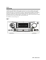
Reviews: