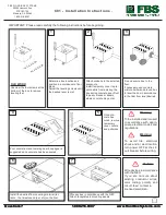
Motorola DCH70, Installation Manual
The Motorola DCH70 installation manual is a comprehensive guide designed to assist users in seamlessly setting up their device. With step-by-step instructions and detailed diagrams, this manual ensures a hassle-free installation process. Download the user manual for free from our website manualshive.com and maximize the potential of your Motorola DCH70.
Share
Download


Reviews:
No comments
Related manuals for DCH70
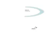
C01
Brand: FBS Pages: 2
C-BOX 100
Brand: Datalogic Pages: 25
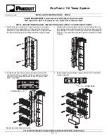
PN79G
Brand: Panduit Pages: 2
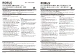
Robus REX4P0-01
Brand: LED Group Pages: 3
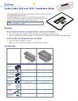
Cable Cubby 1202
Brand: Extron electronics Pages: 8
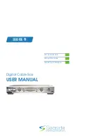
DCT 6208
Brand: Seaside Communications Pages: 48
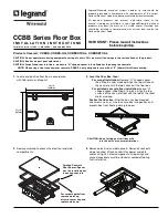
CCBBS
Brand: LEGRAND Pages: 4
Cable Box
Brand: Sony Pages: 48
3VA9-0JA1 Series
Brand: Siemens Pages: 4
DCT2500
Brand: Motorola Pages: 54
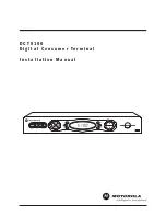
DCT5100
Brand: Motorola Pages: 2
DCT5100
Brand: Motorola Pages: 81
NDA-31135
Brand: NEC Pages: 38
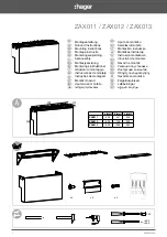
ZAX011
Brand: hager Pages: 2
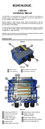
CBX100
Brand: Datalogic Pages: 8

Defender Series
Brand: Adam Hall Pages: 100

Defender Compact
Brand: Adam Hall Pages: 56
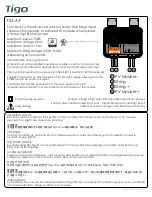
TS4-A-F
Brand: Tigo Pages: 2


