background image


Canopy™ T1/E1 
Multiplexer 
 
User Guide 


T1E1Mux-UG-en 
Issue 3 
September 2004 


Summary of Contents for Canopy T1/E1

Page 1: ...Canopy T1 E1 Multiplexer User Guide T1E1Mux UG en Issue 3 September 2004 ...

Page 2: ...1 2 3 IDU Physical Description 11 1 2 4 Rear Panel 11 1 2 5 Front Panel 14 1 2 6 Features 15 1 2 7 Specifications 15 1 3 Configuration Settings from Canopy Factory 17 1 3 1 Bit Handling Capability 17 1 3 2 License Keys 18 1 3 3 Power Adapters 18 1 4 Product Labels 18 1 5 Functional Description of the Canopy T1 E1 Multiplexer 18 1 5 1 Channel Modes 19 1 5 2 Encoding 19 1 5 3 Signaling 21 1 5 4 Timi...

Page 3: ...guring the Canopy T1 E1 Multiplexer using the CLI 34 2 3 5 Creating a Login Account 35 2 4 Configuration Procedures Using the CLI 36 2 4 1 Logging into the System 36 2 4 2 Changing the Administrator Password 36 2 4 3 Select Line Type T1 or E1 37 2 4 4 Select Line Coding 38 2 4 5 Configure Ports 39 2 4 6 Configure Timing 44 2 5 Configuration Procedures Using the EMS 45 2 5 1 Logging into the System...

Page 4: ...munications Standards Institute 72 4 3 Trademarks Product Names and Service Names 72 4 4 References 73 LIST OF FIGURES Figure 1 Canopy T1 E1 Multiplexer with Canopy BHs 10 Figure 2 Canopy T1 E1 Multiplexer rear panel 11 Figure 3 Rear panel with standard 110 v source power supply 12 Figure 4 Standard adapters for global use 12 Figure 5 Rear panel with optional 48 v power supply adapter for battery ...

Page 5: ...t Upgrade window 61 Figure 27 Key accepted window 61 Figure 28 Invalid key entry window 62 Figure 29 Canopy T1 E1 Mux Configuration window 62 LIST OF TABLES Table 1 Font types 8 Table 2 Admonition types 8 Table 3 LED status indicator descriptions 14 Table 4 Canopy T1 E1 Multiplexer physical specifications 15 Table 5 T1 port specifications 16 Table 6 T1 framing specifications 16 Table 7 E1 port spe...

Page 6: ...44 Procedure 14 Logging in using the EMS 45 Procedure 15 Changing Administrator password using the EMS 48 Procedure 16 Selecting line type T1 or E1 using the EMS 49 Procedure 17 Configuring T1 line coding using the EMS 49 Procedure 18 Configuring E1 line coding using the EMS 50 Procedure 19 Configuring the Ethernet ports using the EMS 50 Procedure 20 Configuring the T1 ports using the EMS 50 Proce...

Page 7: ...tup on Page 28 clarifies how Ethernet cables must be selected 1 1 2 Using the Latest Information When Canopy T1 E1 Multiplexers are shipped the latest issue of this document is included on CD ROM with the shipment However the latest issue at any time is available on the Canopy web site http www motorola com canopy posted among the user guides that support other Canopy products You can distinguish ...

Page 8: ...used admonitions Each of these types of admonitions has a general purpose that underlies the specific information in the box These purposes are indicated in Table 2 Table 2 Admonition types Admonition Label General Message NOTE informative content that may defy common or cursory logic describe a peculiarity of the Canopy implementation add a conditional caveat provide a reference explain the reaso...

Page 9: ...chnical documentation canopywireless com 1 2 INTRODUCTION TO CANOPY T1 E1 MULTIPLEXER This user guide provides the installation and configuration requirements for the Canopy T1 E1 Multiplexer a modular gateway that works with Canopy Backhaul Modules to enable up to four T1 or up to three E1 circuits to be extended over Ethernet networks The Canopy T1 E1 Multiplexer is available in two power config...

Page 10: ...rate as either a T1 or an E1 device Applications of the T1 E1 Multiplexer include obviating leased lines implementing wireless PBX networking establishing cellular backhaul links providing homeland security backup or emergency voice networks routing LAN WAN data on excess bandwidth 1 2 1 Ethernet Interface The Ethernet physical layer auto negotiation should be set to on for both sides of the Canop...

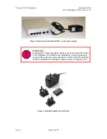
Page 11: ...802 3 G 824 EMC Class A compliance EN 55022 Class A ANSI T1 403 1 2 3 IDU Physical Description The unit provides a compact simple to configure and easily scalable solution for transporting T1 E1 services over Canopy wireless Ethernet based networks 1 2 4 Rear Panel Interface connections and the power port are located on the rear panel of the unit Figure 2 Canopy T1 E1 Multiplexer rear panel Issue ...

Page 12: ...power supply WARNING An external AC surge suppression device must be used with the Canopy T1 E1 Multiplexer For infrastructure installations Canopy Engineering recommends an AC line surge suppression unit that meets the standard IEC 801 5 EN61000 4 5 Maximum Surge Voltage 1 2x50µsec 6 KV Figure 4 Standard adapters for global use Issue 3 ...

Page 13: ...E1 port s See Figure 2 on Page 11 2 Connect the Ethernet cable from the Canopy Backhaul Module to the jack labeled Canopy See Figure 2 on Page 11 3 Connect the selected power adapter to the T1 E1 Multiplexer See Figure 3 and Figure 4 4 Power the T1 E1 Multiplexer on See Figure 3 5 As required to configure the T1 E1 Multiplexer connect a notebook computer to the jack labeled CONTROL on the front pa...

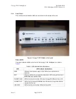
Page 14: ...xer are listed in Table 3 Table 3 LED status indicator descriptions LED LED indicator descriptions PWR ON when main power supply is OK OFF when a malfunction is detected RDY ON when self test is successfully completed OFF during self test and BLINKING when self test fails CANOPY LINK OFF when line is not active ON when Canopy BH Ethernet line is OK CANOPY ACT OFF when no activity BLINKNG when fram...

Page 15: ...ing protocols on T1 E1 10Base T 100Base TX uplink to the network management interfaces simplified troubleshooting through T1 E1 line loopback test 1 2 7 Specifications Physical Specifications Table 4 lists the physical specifications for the Canopy T1 E1 Multiplexer Table 4 Canopy T1 E1 Multiplexer physical specifications Specification Description Option 1 100 240 v 47 63 Hz 0 4 A 3 3 v DC DC Powe...

Page 16: ... ohms Signal levels Receive 0 to 27 dB Transmit 2 7 v 10 adjustable measured in range 0 to 655 feet Jitter Performance AT T TR 62411 G 824 Standards Table 6 T1 framing specifications Specification Description Compliance ANSI T1 403 Framing D4 ESF transparent Signaling CAS Robbed bit signaling CCS transparent Table 7 E1 port specifications Specification Description Ports 1 2 and 3 Compliance ITU T ...

Page 17: ...3 1 Bit Handling Capability As shipped Canopy T1 E1 Multiplexers transparently pass all T1 or E1 bits regardless of user framing as D4 Extended Superframe ESF user encoding as AMI B8ZS HDB3 However user encoding is helpful for generating meaningful bipolar variation BPV data Canopy T1 E1 Multiplexers are factory preset to the B8ZS encoding for T1 though easily changed to another encoding scheme an...

Page 18: ... installations Canopy Engineering recommends an AC line surge suppression unit that meets the standard IEC 801 5 EN61000 4 5 Maximum Surge Voltage 1 2x50µsec 6 KV The 48 v screw down adapter for battery backup pictured in Figure 5 on Page 13 is an option 1 4 PRODUCT LABELS Labels on the Canopy T1 E1 Multiplexer include ESN Electronic Serial Number the Media Access Control MAC address MSN Model Ser...

Page 19: ...aming types or for T1 signaling bits Both 56 kbps and 64 kbps channels are transparently passed The user must identify which type of T1 is being used Alternate Mark Inversion AMI or Binary Eight Zero Substitution B8ZS in order for the Canopy T1 E1 Multiplexer to properly ascertain bipolar violations BPV A bipolar violation is a non zero signal element in an AMI signal that has the same polarity as...

Page 20: ...nt B8ZS HDB3 The Canopy T1 E1 Multiplexer fulfills the role of a transparent T1 E1 extender As such it is compatible with either AMI B8ZS or HDB3 coding of signals The endpoints determine which of the zero suppression techniques will be applied to the signal The Canopy T1 E1 Multiplexer must be set to match the zero suppression settings at the endpoints of the signal The 1 in 15 Requirement AMI Th...

Page 21: ...lity The more accurate clocks are listed at the top of the hierarchy A conventional hierarchy for T1 is defined and is used by Local Exchange Carriers LECs This hierarchy is called a Building Integrated Tuning Supply BITS hierarchy and the formal specifications and standards for this hierarchy are given in the ANSI standards T1 101 1999 and T1 105 09 1996 The highest quality clocks are called Stra...

Page 22: ...ultiplexer may be configured to synchronize to a near end or far end Canopy T1 E1 Multiplexer Master and Secondary Clocks The clock on each Canopy T1 E1 Multiplexer must be correctly configured to prevent frame slips Each of the four 4 T1 E1 ports may be configured as the Master clock source or the Secondary clock source Any port may be set to Master and any port may be set to Secondary however th...

Page 23: ... Canopy T1 E1 Multiplexer is derived from the far end device s transmit clock the far end Canopy T1 E1 Multiplexer Receive clock In this mode a buffer is used to accommodate bursts of Ethernet traffic The buffer is on average maintained at a constant level As the buffer fills the Transmit clock increases in frequency to avoid overflow As the buffer empties the Transmit clock decreases in frequency...

Page 24: ...as it would be without the Canopy T1 E1 Multiplexer For example when the Canopy T1 E1 Multiplexer is inserted between the two PBXs the one PBX will remain as the master clock source and the other PBX will remain as the slave clock source The Canopy T1 E1 Multiplexer should be configured in the following manner The Canopy T1 E1 Multiplexer connected to the master clock source should be configured i...

Page 25: ...the Canopy BH module is a 100 Mbps full duplex port transmitting at a throughput rate that does not cause buffer overload in the Canopy modules The LAN side Ethernet port connected to the customer LAN also transmits at 100 Mbps full duplex The Canopy T1 E1 Multiplexer will insert T1 E1 traffic into the Ethernet bit stream and therefore the Ethernet throughput will be reduced by approximately 2 Mbp...

Page 26: ... directional delay between the two T1 E1 endpoints would be approximately 20 milliseconds This delay does not include any delay added by Canopy Backhaul Modules The Ethernet throughput delay is the time required for one Ethernet packet to pass through the LAN port of the Canopy T1 E1 Multiplexer The maximum one directional delay for an Ethernet packet of size 1518 Bytes is approximately 240 micros...

Page 27: ... equipment is to be connected to a Lightning Surge Protection Device that meets all applicable national safety requirements See Power Supply Unit on Page 27 2 1 3 Electrocution Hazard WARNING Electrocution Hazard This product is intended to be connected to either a 3 3 v DC power source supplied by Canopy or an external 48 v DC supply which must be electrically isolated from any AC sources and rel...

Page 28: ...e appropriate type of cable for connection to the Ethernet port of the Canopy T1 E1 Multiplexer as follows For connection to a LAN or a switch a straight through cable is required For connection to the NIC card in a PC a crossover cable is required For connection to a PBX a T1 E1 crossover cable is likely required Refer to your PBX installation instruction manual for specific requirements 2 2 3 Mo...

Page 29: ...h the screw holes 6 Tighten screws 7 Insert the screw posts onto the DB 9 connector 8 Tighten screw posts 9 Mount the Canopy T1 E1 Multiplexer with the rack panel onto your rack unit Consult the product information supplied by the rack manufacturer for details NOTE The front panel mounting screws should be 4 40 screws between 3 8 and 5 8 long end of procedure 2 2 4 Connecting the Canopy T1 E1 Mult...

Page 30: ... cables to the T1 E1 ports NOTE There is a one to one relationship between the T1 E1 ports on the Canopy T1 E1 Multiplexer This means that the T1 E1 cable connected to the T1 E1 Port 1 on one of the Canopy T1 E1 Multiplexers must also be connected to Port 1 on the other 2 Connect the Ethernet cables to the Ethernet ports 3 Connect the power cable to the power connector end of procedure 2 2 5 Conne...

Page 31: ... 3 Connect the AC adapter to the DC IN port on the rear of the Canopy T1 E1 Multiplexer end of procedure Follow this procedure to connect the to an external 48 v DC power source Procedure 4 Connecting the 48 v DC power source CAUTION Ensure correct polarity before connecting external DC supply to Canopy T1 E1 Multiplexer 1 Connect the power cables to the terminal strip ensuring the correct polarit...

Page 32: ... ROM Follow these steps to install the software that is provided by Motorola Canopy on the CD ROM onto your PC 1 Load software onto your PC The T1 E1 Multiplexer EMS Graphical User Interface is provided by Canopy on a CD ROM that is shipped with the unit 2 Install the software from the CD ROM by double clicking the setup application or 3 Issue the Start Run d setup sequence where d is the drive le...

Page 33: ...interface GUI provides a user friendly graphical display that allows easy to follow steps to configure the unit Fault isolation statistics and events gathering are available The GUI simplifies field installation Examples of drop down menus are provided in Figure 14 and Figure 15 Figure 14 File drop down menu in GUI Figure 15 Config drop down menu in GUI Issue 3 ...

Page 34: ...HyperTerminal 1 Connect the serial cable from the DB9 serial port on a PC to the Serial port on the Canopy T1 E1 Multiplexer The DB9 connector on Canopy T1 E1 Multiplexer is female the cable from the PC is male A straight through cable is required 2 Start HyperTerminal or another terminal emulation program 3 Set the terminal emulation program to emulate a VT100 terminal with the following settings...

Page 35: ... Version 3 4 Page 35 of 73 Figure 16 Command Line Interface window 2 3 5 Creating a Login Account The system is shipped with default setting for the Administrator account The account is active but it is recommended you change the password for this account Issue 3 ...

Page 36: ... default administrator account username and password 2 4 CONFIGURATION PROCEDURES USING THE CLI 2 4 1 Logging into the System To gain access to the CLI log into the system as described under Configuration Procedures Using the EMS 2 4 2 Changing the Administrator Password Procedure 7 Changing Administrator password using the CLI Use this procedure to use the CLI manager to change the Administrator ...

Page 37: ...RESULT The system returns the line type for all four ports as in the following example Line type T1 E1 Set line type Enter set line type T1 E1 where T1 sets the line type to T1 for all 4 ports E1 sets the line type to E1 for all 4 ports RESULT The system acknowledges the new setting for line type for all four ports as in the following example Line type T1 E1 Reset system Enter reset RESULT The sys...

Page 38: ...r password Set line code Enter set line 1 2 3 4 code HDB3 B8ZS AMI where HDB3 sets the line type to HDB3 for all 4 E1 ports B8ZS sets the line type to B8ZS for all 4 T1 ports AMI sets the line type to AMI for all 4 E1 or T1 ports RESULT The system selects the line code for all four ports as in the following example Line code 1 2 3 4 set to HDB3 B8ZS AMI Get line code Enter get line code RESULT The...

Page 39: ...r password Set BH side Ethernet auto negotiation Enter set canopy port auto negotiation on off where on enables auto negotiation at 100 Mbps Full Duplex as default off forces the port to 100 Mbps Full Duplex without auto negotiation RESULT The system responds Canopy port auto negotiation is on Set LAN side Ethernet auto negotiation Enter set lan port auto negotiation on off where on enables auto n...

Page 40: ...oice lines The default length is 133 ft Enter set line 1 2 3 4 length 133 266 399 533 where 1 2 3 4 represents T1 ports 1 through 4 133 266 399 533 655 represents line length in feet RESULT The system responds Line 1 2 3 4 length 0 133 0 6 dB 133 266 1 2 dB 266 399 1 8 dB 399 533 2 4 dB 533 655 3 0 dB Set T1 line code NOTE If the line code does not match the incoming T1 settings then Bipolar Viola...

Page 41: ...d Set master clock reference line NOTE This is the master clock reference for all four T1 E1 lines The default setting is T1 E1 Port 1 Enter set master clock reference line 1 2 3 4 where 1 2 3 4 represents T1 E1 ports 1 through 4 RESULT The system responds Clk ref line 1 2 3 4 Set backup clock reference line NOTE This is the optional backup clock reference for all four T1 E1 lines The backup clock...

Page 42: ...oice lines The default length is 133 ft Enter set line 1 2 3 4 length 133 266 399 533 where 1 2 3 4 represents E1 ports 1 through 4 133 266 399 533 655 represents line length in feet RESULT The system responds Line 1 2 3 4 length 0 133 0 6 dB 133 266 1 2 dB 266 399 1 8 dB 399 533 2 4 dB 533 655 3 0 dB Set E1 line code NOTE If the line code does not match the incoming E1 settings then Bipolar Viola...

Page 43: ...tem responds Clock source is recovered Set master clock reference line NOTE This is the master clock reference for all four T1 E1 lines The default setting is T1 E1 Port 1 Enter set master clock reference line 1 2 3 4 where 1 2 3 4 represents T1 E1 ports 1 through 4 RESULT The system responds Clk ref line 1 2 3 4 Set backup clock reference line NOTE This is the backup clock reference for all four ...

Page 44: ... reference line NOTE This is the master clock reference for all four T1 E1 lines The default setting is T1 E1 Port 1 Enter set master clock reference line 1 2 3 4 where 1 2 3 4 represents T1 E1 ports 1 through 4 RESULT The system responds Clk ref line 1 2 3 4 Set backup clock reference line NOTE This is the optional backup clock reference for all four T1 E1 lines The backup clock reference becomes...

Page 45: ...ystem responds Clock source is recovered Log off Enter lo RESULT The system responds goodbye end of procedure 2 5 CONFIGURATION PROCEDURES USING THE EMS 2 5 1 Logging into the System Procedure 14 Logging in using the EMS If you are using the EMS to access the system follow the steps below to log in 1 Select the proper COM Port for your PC NOTE COM1 through COM4 are supported 2 Enter the User Name ...

Page 46: ...E1 Multiplexer September 2004 T1 E1 Multiplexer FPGA Version 3 4 Page 46 of 73 Figure 17 Login dialogue box Once you are successfully logged in the T1 E1 Multiplexer EMS Main Menu opens shown in Figure 18 Issue 3 ...

Page 47: ...September 2004 T1 E1 Multiplexer FPGA Version 3 4 Page 47 of 73 Figure 18 T1 E1 Multiplexer EMS main menu end of procedure NOTE You can access CLI commands by selecting File Command Line Terminal from the EMS Main menu Issue 3 ...

Page 48: ...ime Figure 19 Change Password dialogue box Procedure 15 Changing Administrator password using the EMS Use this procedure to change the password from the EMS 1 Select File Change password from the main menu RESULT The Change Password dialogue box opens shown in Figure 19 2 Type the old password then press Enter or Tab 3 Type the new password then press Enter or Tab 4 Enter the new password again th...

Page 49: ...n window pops up 8 To reset the system select Yes 9 Select Close RESULT The dialogue box closes and you are returned to the EMS main menu end of procedure 2 5 4 Select Line Coding Procedure 17 Configuring T1 line coding using the EMS Follow these steps to configure T1 line coding from the EMS 1 From main menu EMS select the Configuration Config option 2 Select Configure T1 RESULT The Config dialog...

Page 50: ...se the dialogue box once all channels are configured RESULT You are returned to the EMS main menu end of procedure 2 5 5 Configure Ports Procedure 19 Configuring the Ethernet ports using the EMS Follow these steps to configure the Ethernet ports using the EMS 1 From the Main Menu select the pull down menu Config Ethernet RESULT The Ethernet Configuration dialogue box opens 2 Indicate the appropria...

Page 51: ... Tx clock back to the Rx Recovered mode recovers the clock from the incoming T1 E1 over Ethernet bit stream from the far end T1 E1 13 When all channels are configured select Close to close the dialogue box RESULT You are returned to the EMS main menu end of procedure Procedure 21 Configuring the E1 ports using the EMS Follow this procedure to configure the E1 ports from the EMS 1 From the pull dow...

Page 52: ... timing using the EMS Use this procedure to configure the timing using the EMS 1 Select Config T1 from the pull down menu RESULT The T1 Config dialogue box opens 2 Click for Master Clock Reference Line 3 Select which line is to be designated as the master clock reference line 4 Click for Secondary Clock Reference Line 5 Select which line is to be designated as the secondary clock reference line 6 ...

Page 53: ... T1 E1 Multiplexer To do so requires an Ethernet to RS 232 converter An example of such a converter is available at http www precidia com products product1 html The configuration for remote management is illustrated in Figure 20 Canopy T1 E1 Multiplexer DB9 3 3 v Wall Mount Supply Canopy Ethernet To Ethernet Network To E1 T1 Lines Lightning Surge Protector Power over Ethernet Canopy ODU 48 v DC Su...

Page 54: ...in At the password prompt enter password View T1 E1 Alarms Enter get alarms The system responds displays alarms for all 4 T1 E1 ports as in the following example Line1 Line code violation No Receive Loss of Signal No Alarm Indication Signal Detect No Line2 Line code violation No Receive Loss of Signal No Alarm Indication Signal Detect No Line3 Line code violation No Receive Loss of Signal No Alarm...

Page 55: ...reen light meaning no current alarms and a red light meaning that there is a current alarm The alarms are also displayed in text form No means that there is not a current alarm Yes means that there is a current alarm 2 The Alarms Log window lists alarms that have occurred for all 4 T1 E1s while the window is open An alarm log file is automatically written for all 4 T1 E1s The file exits in the sam...

Page 56: ... system Enter reset RESULT The system responds Resetting then immediately resets both Ethernet Interfaces and all 4 T1 E1 interfaces without asking for a confirmation end of procedure Follow these steps to reset the system using the EMS Procedure 26 Resetting the system using the EMS 1 Select the File Reset menu option RESULT A confirmation window pops up 2 To reset the system select Yes NOTE Sele...

Page 57: ...e The near end T1 E1 Transmit is looped back to the near end Receive and the far end T1 E1 transmit that arrives over the BH Ethernet port is looped back to the far end Receive The T1 E1 loopback remains in effect until the user removes the loopback through the CLI or through the EMS or the system is reset CAUTION Invoking a T1 E1 Loopback will drop voice calls and disrupt user traffic flow Figure...

Page 58: ...s 1 through 4 on will enable T1 E1 loopback off will remove the T1 E1 loopback The system responds Line 1 2 3 4 loopback is on off Log off Enter lo RESULT The system responds goodbye end of procedure 3 4 2 Invoking a T1 E1 Loopback Using the EMS Procedure 28 Invoking a T1 E1 loopback using the EMS Use this procedure to invoke a T1 E1 Loopback from the EMS 1 Select the Test Loopback menu option RES...

Page 59: ...t corrects BPVs Frame errors Incorrect values in the framing bit position In service or out of service Approximates bit error rate on in service basis Evaluates only overhead bits CRC errors Bit errors in a block of data In service or out of service 98 4 bit error rate accuracy Available with only ESF framing 3 6 FIRMWARE UPGRADES Firmware upgrades are periodically made available to enhance perfor...

Page 60: ...SULT The status bar indicates the progress of the download process IMPORTANT During the download process do not interrupt the download process 6 Wait until the download is complete 7 Reset the T1 E1 Multiplexer according to Procedure 26 on 56 RESULT The upgrade process is complete 8 From the main menu of the EMS select Help About Canopy T1 E1 Mux 9 Verify that the intended firmware version is indi...

Page 61: ... license key on a Canopy T1 E1 Multiplexer perform the following steps 1 From the main menu of the EMS select Config T1 E1 Port Upgrade Config Software Upgrade shown in Figure 15 on Page 33 RESULT The Canopy T1 E1 Port Upgrade window opens as shown in Figure 26 Figure 26 T1 E1 Port Upgrade window 2 Type in the upgrade key that your Canopy distributor provided for this unit then press Enter 3 Click...

Page 62: ...ber of enabled ports as follows 4 From the main menu select Config Canopy T1 E1 Mux RESULT The Canopy T1 E1 Mux Configuration window opens as shown in Figure 29 Figure 29 Canopy T1 E1 Mux Configuration window 5 In the lower right quadrant of the window find the Enabled T1 E1 Ports block NOTE Each enabled port is identified by a black check mark end of procedure Issue 3 ...

Page 63: ...nterest in or to the Software but only a limited right of use You agree not to disclose it or make it available to anyone without Motorola s written authorization You will exercise no less than reasonable care to protect the Software from unauthorized disclosure You agree not to disassemble decompile or reverse engineer or create derivative works of the Software except and only to the extent that ...

Page 64: ...o operate on Motorola equipment you may not transfer the Software to another party except 1 if you are an end user when you are transferring the Software together with the Motorola equipment on which it operates or 2 if you are a Motorola licensed distributor when you are transferring the Software either together with such Motorola equipment or are transferring the Software as a licensed duly paid...

Page 65: ...g a period of one year from the date of purchase by the customer If a product is found defective during the warranty period Motorola will repair or replace the product with the same or a similar model which may be a reconditioned unit without charge for parts or labor IN NO EVENT SHALL MOTOROLA BE LIABLE TO YOU OR ANY OTHER PARTY FOR ANY DIRECT INDIRECT GENERAL SPECIAL INCIDENTAL CONSEQUENTIAL EXE...

Page 66: ...AQs to see whether the problem and a solution are present 11 Escalate the problem to Canopy systems Technical Support or another Tier 3 technical support that has been designated for you as follows a Compose e mail to technical support canopywireless com In this email Describe the problem Describe the history of the problem List your attempts to solve the problem Attach the above files List the fi...

Page 67: ...Gets the auto negotiation mode for the Canopy BH Ethernet port If auto negotiation is set to OFF the port will be forced to 100 Mbps Full Duplex Get LAN side Ethernet auto negotiation Enter get lan port auto negotiation The system responds LAN port auto negotiation is on off Get the auto negotiation mode for the customer LAN Ethernet port If auto negotiation is set to OFF the port will be forced t...

Page 68: ...n feet in decibels If the incorrect line length is selected the result could be decreased T1 quality or echo on voice lines Get T1 line code Enter get code line 1 2 3 4 where 1 2 3 4 represents T1 ports 1 through 4 The system responds Line 1 2 3 4 code B8ZS AMI Gets the T1 line code If the line code does not match Bipolar Violations BPVs will occur Get E1 line code Enter get code line 1 2 3 4 wher...

Page 69: ...clock from the far end T1 Get the master clock reference line Enter get master clock reference line The system responds Clk ref line 1 2 3 4 NOTE 1 2 3 4 represents T1 E1 ports 1 through 4 Displays the T1 master clock reference line This clock reference applies for all four T1 lines Get the secondary clock reference line Enter get secondary clock reference line The system responds Backup clk ref l...

Page 70: ... No Line3 Line code violation No Receive Loss of Signal No Alarm Indication Signal Detect No Line4 Line code violation No Receive Loss of Signal No Alarm Indication Signal Detect No FPGA 00 Read Serial Number Reads the serial number of the Canopy T1 E1 Multiplexer Get T1 E1 Loopback Mode Enter get loopback line 1 2 3 4 where 1 2 3 4 represents T1 E1 ports 1 through 4 The system responds Line 1 2 3...

Page 71: ...device must accept any interference received including interference that may cause undesired operation This equipment has been tested and found to comply with the limits for a Class A digital device pursuant to Part 15 of FCC rules These limits are designed to provide reasonable protection against harmful interference when the equipment is operated in a commercial environment This equipment genera...

Page 72: ...cations Standards Institute Statement of Compliance Information to User This equipment has been tested and found to comply with the European Telecommunications Standard ETS 300 328 This standard covers Wideband Data Transmission Systems referred to in CEPT Recommendation T R 10 01 This type accepted equipment is designed to provide reasonable protection against harmful interference when the equipm...

Page 73: ...veland Robert F Jr David M Sylvar and Jerry L Ulcek Federal Communications Commission Office of Engineering and Technology OET Bulletin No 65 Edition 97 01 August 1997 Evaluation Compliance with FCC Guidelines for Human Exposure to Radiofrequency Electromagnetic Fields European Telecommunications Standard ETS 300 328 2nd Edition November 1996 Radio Equipment and System RES Wideband Transmission Sy...

Reviews: