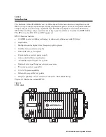
background image

Installation and 
Operation Manual

BT100
1 GHz Broadband
Telecommunications
Amplifier

1

2

5

4

8

3

6

7

Summary of Contents for BT100

Page 1: ...Installation and Operation Manual BT100 1 GHz Broadband Telecommunications Amplifier 1 2 5 4 8 3 6 7 ...

Page 2: ...atings marked at the location of the fuse Electrostatic discharge ESD can damage the BT100 unit and circuit card assemblies Wear an antistatic wrist strap attached to a chassis ground to prevent ESD damage This equipment operates over the marked Voltage and Frequency range without requiring manual setting of any selector switches Different types of line cord sets may be used for connections to the...

Page 3: ...xigences du Règlement sur le matériel brouilleur du Canada International Declaration of Conformity We Motorola Inc 101 Tournament Drive Horsham PA 19044 U S A declare under our sole responsibility that the STARLINE Model BT100 to which this declaration relates is in conformity with one or more of the following standards EMC Standards EN55022 EN55024 EN55013 EN50083 2 CISPR 22 CISPR 24 CISPR 13 Saf...

Page 4: ...y 2 7 Forward Path 2 9 Return Path 2 11 Ingress Control Switch 2 12 Options and Accessories 2 13 Section 3 Amplifier Setup Proper Handling Procedures 3 1 Field Practice 3 1 Bench Setup 3 1 Forward Path Alignment 3 2 Before You Begin 3 2 STARLINE Forward Equalizers 3 3 Example 1 3 3 Example 2 3 3 STARLINE Cable Simulators 3 5 Input Midstage and Output Pads 3 6 Flatness Control 3 7 Directional Coupl...

Page 5: ...t and Connections 4 1 Measuring Forward Gain 4 2 Example 4 2 Testing Return Gain and Response 4 3 Completing the Test Procedures 4 4 Section 5 Installation Aerial Installation 5 1 Pedestal Installation 5 3 Grounding the BT100 5 3 Section 6 Operating Tips Using Amplifiers in Lower Frequency Systems 6 1 Using Amplifiers in Lower Gain Systems 6 1 Appendix A Specifications Model BT100 A 1 AC Current A...

Page 6: ... 10 Figure 2 11 BT100 3 three output block diagram 2 11 Figure 2 12 LL BTA HMS status monitor 2 12 Figure 2 13 BT100 Options and Accessories 2 14 Figure 3 1 Equalizer slope versus cable 3 4 Figure 3 2 Frequency versus cable slope 3 6 Figure 3 3 Flatness controls 3 7 Figure 3 4 BDR 1G board top left bottom right 3 8 Figure 3 5 TDU cable selector 3 10 Figure 3 6 ADU 3 11 Figure 3 7 QADU 3 11 Figure ...

Page 7: ...00 is also FCC CE and CCC approved BT100 features include 1003 MHz power doubling technology in enhanced gallium arsenide E GaAs Ergonomics Multiple modular diplex filter frequency split options 16 dB return loss forward path 60 90 VAC line power option Power factor corrected power supply Auto controlled Bode equalization 20 dB directional coupler test points Optional return path ingress control a...

Page 8: ...1 2 Introduction BT100 Installation and Operation Manual Figure 1 2 illustrates an open BT100 Figure 1 2 BT100 open ...

Page 9: ...eviations and Acronyms The Abbreviations and Acronyms list contains the full spelling of the short forms used in this manual This Installation and Operation Manual assumes that all channels are standard National Television Standards Committee NTSC analog channels Refer to catalog specifications for further details pertaining to signal levels of digital channels above 550 MHz This Installation and ...

Page 10: ...ducts PRESS 3 Products PRESS 1 Cable Router VOIP PRESS 2 Cable Modems Products PRESS 3 Transmission Transport Products MBT MWT MEA PRESS 5 Multiservice Management PRESS 4 Network Licensing PRESS 1 Network Management Products PRESS 2 Network Technical Response Center Telephone Menu Options Connected Home Solutions Video Products PRESS 1 Issued 04 2005 Broadcaster Satellite IRD or Encoder Products P...

Page 11: ...00 AM to 5 00 PM Central Time Monday through Friday When calling from outside the United States use the appropriate international access code and then call 956 541 0600 to contact the Repair Facility When shipping equipment for repair follow these steps 1 Pack the unit securely 2 Enclose a note describing the exact problem 3 Enclose a copy of the invoice that verifies the warranty status 4 Ship th...

Page 12: ...istribution system The BT100 is powered by the 60 90 VAC cable supply and can be configured to pass this power to additional amplifiers and line extenders Installation of the return path enables two way signal flow The standard model BT100 includes an amplifier electronics module with an integrated power supply which is furnished complete in the model BT 100 15 housing as shown in Figure 2 1 You m...

Page 13: ...2 2 Overview BT100 Installation and Operation Manual Figure 2 2 illustrates the various output port configurations Figure 2 2 BT100 output port configurations ...

Page 14: ...ailable The BT100 is fully configured in the factory per model requested You can find the model name on labels on the outside of the shipping carton the side of the BT100 housing and the side of the electronics module Figure 2 3 identifies and describes the model strings Figure 2 3 BT100 ordering guide ...

Page 15: ...hed in the BT 100 15 housing The housing protects the electronics from weather and dissipates internally generated heat Figure 2 4 illustrates the top view of the BT 100 15 housing and provides its dimensions Figure 2 4 BT 100 15 dimensions top view Figure 2 5 illustrates a side view of the BT 100 15 housing and provides its dimensions Figure 2 5 BT 100 15 dimensions side view ...

Page 16: ... the housing Two messenger clamps are attached to the side of the housing Figures 2 5 2 7 and are secured with 5 16 inch x 24 threads per inch stainless steel bolts for strand aerial mounting The bottom of the housing also contains two 5 16 inch x 24 threaded holes located on the horizontal center line separated by eleven inches center to center Figure 2 7 Use these holes and the bolts from the me...

Page 17: ...re 2 6 These gaskets provide efficient ground continuity RF shielding and weather protection Both gaskets must be in place and in good condition to ensure proper operation and protection of the station The weather gasket should be lightly coated with silicone grease each time the amplifier is opened Replace this gasket if it becomes damaged or deformed Figure 2 6 illustrates the housing gaskets Fi...

Page 18: ...wave The power supply incorporates power factor correction that presents a near perfect power factor to the input line This reduces the AC current and improves the efficiency of the DC supply system that delivers 2 5 A at 24 VDC The AC input to the power supply is between 38 VAC and 90VACrms in two ranges with a line frequency from 50 Hz through 60 Hz A precision output regulator protects against ...

Page 19: ...c models BT 100 H which include a gas discharge tube The FTEC BTA fires at approximately 245 V and presents a short circuit to the line during periods of over voltage After the AC input voltage returns to normal the FTEC BTA resumes its open state Although the power supply is located under the electronics chassis you can access the gas discharge tube or FTEC BTA through the cover on the top side o...

Page 20: ...hile the output stage contributes the preferred power at low distortion The amplifier input provides a facility to install a cable equalizer and a socket for a model JXP B attenuator The attenuator and equalizer are customer installed options Several circuits comprise the mid stage amplifier The Bode equalizer is a voltage controlled device that receives its input from the manual gain control the ...

Page 21: ...urce impedance they do not require special test probes After the output amplifier a second directional coupler provides signal to the optional ADU board As this signal is used only with the ADU you do not need to terminate this port when the ADU is not installed Figure 2 10 illustrates the interconnection between these components in the four output BT100 4 Figure 2 10 BT100 4 four output block dia...

Page 22: ...t and 2 dB increments for all other splits from 0 dB through 12 dB You must install a return equalizer to activate the return path There are JXP B pad facilities located at the inputs and output of the return path You can use these pad facilities as test points or signal injection points The output pad value is normally selected to control the return signal level into the next upstream amplifier w...

Page 23: ...cable connections to the electronics chassis Figure 2 12 LL BTA HMS status monitor The ICS provides a means of isolating sources of ingress from a centralized location Using a downstream command through the LIFELINE status monitoring system you can attenuate the return path through the amplifier by 6 dB or by 38 dB By reducing the ingress level at the headend or monitoring point you can further is...

Page 24: ...output The selection of a pilot frequency QAM modulated digital channel is required TDU Thermal Drive Unit This board controls amplifier output levels that change with cable attenuation for the sensed temperature SFE 100 STARLINE Forward Equalizer This 1GHz equalizer compensates for cable properties in 1 dB increments from 0 dB through 22 dB You must install the appropriate value SRE STARLINE Retu...

Page 25: ...eturn Path Correction Board This optional board provides additional flatness response correction in the return path for systems that must meet especially stringent return path flatness requirements Figure 2 13 illustrates the location of options and accessories in the BT100 Figure 2 13 BT100 Options and Accessories If you are not using an ADU QADU or TDU you can select manual control of the Bode b...

Page 26: ...e forward equalizer and a high value 20 dB or above input pad before you install or remove the electronics chassis or activate the system This significantly reduces RF signal level and avoids possible EOS which can damage the hybrids Leaving the input pad location open if a high value pad is not available A more accurate forward input test point reading is achieved with a high value pad installed ...

Page 27: ...emove the electronics chassis or apply power to the BT100 Leave the forward input pad location open if a high value pad is not available A more accurate forward input test point reading is achieved with a high value pad installed Do not remove or install the electronics chassis cover while the BT100 is powered If you need to remove or install the electronics chassis cover for any reason shut off t...

Page 28: ...oices possible Example 2 The BT100 amplifier is used in a link following a fiber node The fiber receiver output is flat and connects to the input of the amplifier through 18 dB of cable plus passive loss Determine which is the proper equalizer to achieve 11 dB output tilt from the BT100 Calculate the equalizer value using the following equation SLOPEeq TILTout SIGlo SIGhi SLOPEieq where SLOPEeq re...

Page 29: ... 9 3 7 2 4 1 0 18 14 0 15 0 11 0 9 2 6 9 5 7 4 5 3 4 2 2 1 0 16 12 4 13 4 9 9 8 2 6 3 5 2 4 1 3 2 2 1 1 0 14 10 9 11 9 8 7 7 3 5 6 4 6 3 7 2 9 2 0 1 0 12 9 3 10 3 7 6 6 4 5 0 4 1 3 3 2 6 1 8 1 0 10 7 8 8 8 6 5 5 5 4 3 3 6 2 9 2 4 1 7 1 0 8 6 2 7 2 5 4 4 6 3 6 3 1 2 6 2 1 1 5 1 0 6 4 7 5 7 4 3 3 7 3 0 2 6 2 2 1 8 1 4 1 0 4 3 1 4 1 3 2 2 8 2 3 2 0 1 8 1 5 1 3 1 0 2 1 6 2 6 2 1 1 9 1 7 1 5 1 4 1 3 1 ...

Page 30: ...able tilt The simulators fit in the same location as the equalizers Table 3 2 and Figure 3 2 help you choose the correct simulators Table 3 2 Starline cable simulators SCS 1 2 3 4 5 6 7 8 9 10 Frequency Cable slope in dB 40 MHz 0 0 0 1 0 1 0 1 0 2 0 2 0 3 0 3 0 3 0 4 45 MHz 0 0 0 0 0 1 0 1 0 1 0 1 0 1 0 1 0 2 0 2 50 MHz 0 0 0 0 0 0 0 0 0 0 0 0 0 0 0 0 0 0 0 0 72 MHz 0 1 0 2 0 2 0 3 0 4 0 4 0 5 0 6...

Page 31: ...1 Input Midstage and Output Pads Install model JXP B pads to attenuate the signal per system design drawings Generally this consists of attenuating excessive input levels You should pad the input to system level for unity gain Select and install the specified pad in the socket labeled JXP IN on the amplifier cover The midstage pad JXP and output pads JXP OUT JXP 1 JXP 3 and JXP 4 can be used to ad...

Page 32: ...izer plus the contribution of the hybrid gain stages produces approximately 14 dB of tilt Adjust the BDR 1G board to correct peak to valley response variations Adjust or replace the equalizer if the response exhibits tilt Figure 3 3 illustrates the location of the BDR 1G board and the high end flatness adjustment capacitor Figure 3 3 Flatness controls You can adjust the variable resistors and capa...

Page 33: ...value If the module s response is up tilted increase the MEQ 100 value by l dB If the module s response is down tilted decrease the MEQ 100 value by 1 dB Directional Coupler Test Points Accurate 20 dB directional coupler test points are available at the input and at the output of the BT100 Because these test points are 75 ohm source impedance they do not require special test probes After the outpu...

Page 34: ... control select jumper is in the MAN position 4 Use a signal level meter to measure the high band edge carrier input level at the input test point 750 MHz channel 116 870 MHz channel 136 1003 MHz channel 158 This carrier should be at standard analog level non scrambled 5 Verify that the input level agrees with the design specification input If the level is different from design adjust accordingly ...

Page 35: ...t pad by the value of the SCS 9 Measure the output level at the highest frequency It should be within 1 dB of the system design level If it is not you must adjust the midstage pad JXP and or the output pads JXP OUT JXP 1 JXP 3 JXP 4 accordingly Refer to Section 6 Operating Tips for midstage output padding information and recommendations Thermal Drive Unit The TDU senses temperature and controls th...

Page 36: ...oring the amplitude of this frequency Any change in signal level is fed back to the Bode equalizer It is assumed that the encountered signal level changes are due to changes in cable attenuation and hybrid output associated with a change in temperature The Bode equalizer then changes its insertion loss to maintain a constant output level The ADU illustrated in Figure 3 6 and QADU Figure 3 7 mainta...

Page 37: ...alue as shipped from the factory and is appropriate for an amplifier output level range from 43 dBmV to 49 dBmV at 550 MHz Use a JXP 1B pad for output levels below 43 dBmV and a JXP 11B for output levels above 49 dBmV The standard pad for the QADU is a JXP 0B This pad value works for a BT100 output level from 38 dBmV to 47 dBmV at 550 MHz Use a JXP 7B when operating above 47 dBmV at 550 MHz Motoro...

Page 38: ...lizer SRE 100 in the location RTN EQ 4 Verify that the return input pad locations JXP JXP 1 JXP 3 and JXP 4 have 0 dB pads or JXP ZX jumpers installed 5 If you require ICSs install them in the ICS locations illustrated in Figure 2 13 If you plan to install the ICSs later install JXP 2Bs to simulate the through loss of the ICSs This eliminates the need to rebalance the return path if you install th...

Page 39: ...UTION To avoid damage to the hybrids it is recommended that you remove the input pad JXP IN before you apply power to the BT100 A 20 ampere blade type fuse is furnished in each active port of the amplifier module and provides overcurrent protection for AC power applied to the input You can power the BT100 from the output without passing power through to the input port To block power from the input...

Page 40: ...nnected output port F2 F3 F4 or F5 illustrated in Figure 2 9 Terminate all unused ports Open the housing and remove the electronics chassis cover Refer to your system drawings or records to confirm the presence of the required options as described in Section 2 Overview Options and Accessories Reinstall the electronics chassis cover and torque the screws to 10 12 in lbs Test Equipment and Connectio...

Page 41: ...needed 5 Select manual gain by placing the drive control select jumper in the MAN position and turn the MANUAL LEVEL control MAN Figure 2 13 fully clockwise 6 Measure the gain at mixed forward frequency using the procedure outlined in the operator manual provided with the test equipment in use To correct this number add the insertion loss of the SSP PIN power combiner 0 6 dB at 750 MHz 0 7 dB at 8...

Page 42: ...o ensure compliance with specifications When testing the return path remember that it is a flat response Therefore the cable simulator must remain in the test set up and must remain set to the same cable equivalent as in the forward sweep test This provides an approximate indication of the frequency response which you can achieve in the field To test for return gain and response 1 Reconnect the te...

Page 43: ... Completing the Test Procedures The amplifier is now approximately tailored for a specific field location Additional adjustments after installation are minor in nature Re install the fuses removed during testing Complete station records by recording pertinent information Remove test equipment connections and close the housing following instructions provided in Section 5 Installation Closing the Ho...

Page 44: ...es Longer pins can extend past the center conductor seizure mechanism and degrade the match Extremely long pins can result in a short circuit Figure 5 1 Center conductor pin length 1 65 Max 1 50 Min To install the unit 1 Power down the cable before you install the housing This avoids blown fuses tripped circuit breakers and possible personal injury 2 Mount the housing and torque the two 5 16 inch ...

Page 45: ... V and 24 4 V and reinstall the input pad 11 If necessary rebalance the amplifier following the instructions in Section 3 Amplifier Setup 12 Check the tightness of the electronics chassis cover screws 10 to 12 in lbs and hold down bolts 18 to 22 in lbs 13 Check the condition of the RF and weather gaskets and replace them if necessary If needed also apply a light coating of silicone grease 14 Ensur...

Page 46: ...ach is to install a JXP TH C thermal attenuator while operating the BT100 in the manual mode To mount the BT100 on a pedestal 1 Remove two 5 16 inch messenger clamp bolts located on the long sides of the BT100 housing 2 Locate the two 5 16 inch holes Figure 2 7 eleven inches center to center cast in the lower housing 3 Use the two 5 16 inch bolts to install the BT100 to the pre drilled pedestal mo...

Page 47: ... 87 cuts off frequencies above 870 MHz Therefore if you have a 1 GHz system and need the equalizer to perform to 1 GHz you must use an SFE 100 Using Amplifiers in Lower Gain Systems There are three pad facilities in the forward path 1 is the pad location JXP IN at the input to the amplifier 2 is the midstage pad JXP located between the pre amplifier and the interstage hybrid and 3 are the output p...

Page 48: ...nal 42 dB with SFE and slope reserves Flatness 52 through 1003 MHz 0 70 dB maximum Level control automatic Bode board using ADU QADU TDU Gain control Fixed pads JXP B Performance reference frequency MHz 1003 550 52 At typical output dBmV 45 44 37 Channels 79 analog 320 MHz digital suppressed by 6 dB Crossmod worst case 66 dB CTB worst case 75 dB CSO worst case 71 dB Noise figure At 52 MHz 10 dB wi...

Page 49: ...7 5 dB Flatness 0 75 dB Level control Fixed pads JXP B input and output Performance reference frequency MHz 40 At typical output 35 dBmV flat Channels 6 NTSC Crossmod worst case 74 dB CTB worst case 86 dB CSO worst case 82 dB Noise figure 12 5 dB Power requirements 24 VDC 125 mA ADU QADU Automatic Drive Unit Parameter Specification Pilot channel See current catalog Adjacent channel frequency 6 MHz...

Page 50: ...lid closure 5 16 18 1 2 inch 180 15 0 20 4 Test point plugs 5 8 24 1 2 inch 25 40 2 1 3 3 2 8 4 5 Seizure screw 8 32 3 16 inch or Phillips 12 1 0 1 4 Hybrid 6 32 Phillips 10 12 0 8 1 0 1 1 1 4 Chassis electronics module 10 32 5 16 inch 18 22 1 5 1 8 2 0 2 4 Chassis electronics module cover 6 32 1 4 inch or Phillips 10 12 0 8 1 0 1 1 1 4 Status monitor 10 32 5 16 inch 24 30 2 0 2 5 2 7 3 4 Power su...

Page 51: ...s referenced to one millivolt E GaAS Enhanced Gallium Arsenide FTEC Fast Transfer Electronic Crowbar GHz Gigahertz ICS Ingress Control Switch MEQ mid stage equalizer MHz Megahertz NTSC National Television Standards Committee QADU Quadriture Amplitude Modulated QAM Automatic Drive Unit rms root mean square RSA Return for Service Authorization SAW Surface Acoustic Wave SCS STARLINE Cable Simulator S...

Page 52: ...527550 001 a 2 07 Visit our website at www motorola com ...

Reviews: