background image

AP 7161 ACCESS POINT

INSTALLATION GUIDE

Summary of Contents for AP 7161

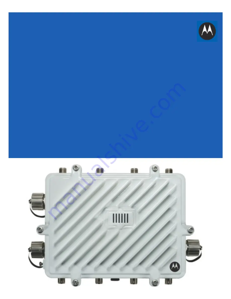
Page 1: ...AP 7161 ACCESS POINT INSTALLATION GUIDE ...

Page 2: ...2 AP 7161 Access Point MOTOROLA SOLUTIONS and the Stylized M Logo are registered in the US Patent Trademark Office Motorola Solutions Inc 2014 All rights reserved ...

Page 3: ... 12 1 8 Hardware Installation Guidelines 13 1 8 1 Precautions 13 1 8 2 Warnings 14 1 9 Access Point Placement 15 1 10 AP 7161 Hardware Overview 15 1 10 1 AP 7161 Ports and Connections 15 1 10 2 AP 7161 Antenna Connectors 16 1 10 3 AP 7161 Console GE1 POE and GE2 Ports 17 1 10 4 AP 7161 Grounding Screw 19 1 11 LED Indicators 20 1 11 1 Two Radio LEDs 21 1 11 2 Three Radio LEDs 22 2 0 AP 7161 Hardwar...

Page 4: ...pecifications 61 4 5 Approvals 61 5 0 Basic Troubleshooting 62 6 0 Regulatory Information 63 6 1 FCC Approval Statement 63 6 2 TDWR Location Information 66 6 3 Wireless Country Approvals 68 6 4 Health and Safety Recommendations 68 6 4 1 Warnings for the Use of Wireless Devices 68 6 4 2 Potentially Hazardous Atmospheres 69 6 5 RF Exposure Guidelines 69 6 5 1 Safety Information 69 6 5 2 Reduce RF Ex...

Page 5: ... 9 CE Marking and European Economic Area EEA 71 6 10 Statement of Compliance 71 6 11 Other Countries 72 6 12 Waste Electrical and Electronic Equipment WEEE 74 6 13 Turkish WEEE Statement of Compliance 75 7 0 Motorola Solutions Support Center 76 8 0 AP 7161 Series ROHS Compliance 77 ...

Page 6: ... or via the controllers By distributing intelligence and control between the wireless controllers and APs the WiNG 5 network can route directly via the best path as determined by factors including the user the location the application and the available wireless and wired resources Once adopted by a Motorola Solutions RFS4000 RFS6000 RFS7000 or NX 9000 series controller the AP 7161 is managed as an...

Page 7: ...y through preemptive intelligence which dynamically senses weak or failing signals securely moves mobile users to alternate APs and boosts signal power to automatically fill RF holes and ensure uninterrupted mobile user access The AP 7161 band unlocked radios allow flexibility and deployment options for the public safety market The powerful radio increases coverage performance and obstruction pene...

Page 8: ...P 7161 models listed in the table above and must be ordered separately Model Part Number Description AP 7161 66040 US AP 7161 OUTDOOR DUAL RADIO 802 11N AP US AP 7161 66040 WR AP 7161 OUTDOOR DUAL RADIO 802 11N AP INTL AP 7161 66040 EU AP 7161 OUTDOOR DUAL RADIO 802 11N AP EU AP 7161 66S40 US AP 7161 OUTDOOR DUAL RADIO 802 11N AP W SENSOR US AP 7161 66S40 WR AP 7161 OUTDOOR DUAL RADIO 802 11N AP W...

Page 9: ...inches Description ML 2452 HPAG5A8 01 2 4 5 8 4 5 7 5 11 Outdoor rated Type dipole Gain 4 5dBi 2 4GHz 7 5dBi 5GHz 5 5dBi 4 9GHz Connector N male ML 2452 VMM3M3 036 2 4 5 8 3 6 4 0 1 5 Outdoor rated Vehicle Mounted MIMO Omni Patch Type VMM Gain 3 6dBi typical to 4 5dBi maximum 2 4GHz 4 5 typical to 5 4 maximum 5 8GHz Connector RP SMA male NOTE The ML 2452 HPAG5A8 01 multi band antenna is suggested ...

Page 10: ...nnector N male ML 2452 VMM3M3 036 2 4 5 8 3 6 4 0 1 5 Outdoor rated Vehicle Mounted MIMO Omni Patch Type VMM Gain 3 6dBi typical to 4 5dBi maximum 2 4GHz 4 5 typical to 5 4 maximum 5 8GHz Connector RP SMA male ML 2452 HPA6X6 036 2 4 5 8 4 0 6 0 4 5 Outdoor rated Type six port omni dipole array 3x2 4G 3x5G Connector Type N male x6 ML 5299 HPA1 01R 4 9 5 8 6 0 11 Outdoor rated Type dipole array Conn...

Page 11: ...t kit KT 158767 01 For more information see AP 7161 Hardware Mounting and Installation on page 23 1 6 AP 7161 Weatherized Ethernet Accessory One RJ45 weatherized connector plug is included with each AP 7161 Access Point If additional plugs are required they can be ordered using the part number listed in the following table Part Number Description AP PSBIAS 7161 US Outdoor IP66 802 3AT gigabit Ethe...

Page 12: ...his document The following items are not included with the AP 7161 Access Point models but can be ordered from Motorola Solutions Antennas Mounting brackets kits PoE power supply and accessories RFS controllers if required The following items are not provided by Motorola Solutions and can be sourced from local hardware suppliers partners or distributors Lightning protection unit Cat5E cable to con...

Page 13: ...ailable off the shelf Lightning Protection Unit LPU be used on all shielded CAT5E Ethernet connections The LPU should be rated for outdoor use For the best possible protection each Access Point requires an LPU be installed adjacent to the Access Point If there is a LAN connection to an indoor network a second LPU is required at the cable entry point to the building Verify that the deployment envir...

Page 14: ...ll this equipment or work with its power circuits during thunderstorms or other weather conditions that could cause a power surge Verify there is adequate ventilation around the device and that ambient temperatures meet equipment operation specifications Avoid contact with overhead power lines Take precautions to avoid injury from falling tools and equipment Crews should wear hard hats in and arou...

Page 15: ...purchased in a two or three radio configuration see AP 7161 Hardware on page 8 Each model has two band unlocked radios that can operate across the 2 4GHz 4 9GHz and 5GHz bands subject to country regulatory approval and outdoor band use An AP 7161 must be installed by trained professionals familiar with RF planning and regulatory limits defined by the regulatory bodies of the country where the devi...

Page 16: ...ors marked R2 A R2 B and R2 C these antenna ports relate to the software settings of radio 2 Care must be taken to provide the correct antenna for the operating band of each port AP 7161 three radio models AP 7161 66S40 US and AP 7161 66S40 WR are configured with eight N type connectors to support two active WLAN data radios and a dedicated sensor radio as the third As with the two radio models R1...

Page 17: ...rts The AP 7161 has Ethernet ports for external console GE1 POE and GE2 connections To gain access to the ports you will need to remove the protective caps NOTE The sensor radio does not function as a WLAN data radio WARNING Antenna ports where no antenna is mounted must be properly terminated using an approved IP67 terminator WARNING All antenna connectors should be covered with weatherproofing t...

Page 18: ...e GE2 WAN port has been configured to permit an attached external device during the configuration process When making connections using these ports a properly rated RJ45 connector is required One weatherproof RJ45 plug kit is provided with each Access Point When connecting cables to the AP 7161 Ethernet ports follow the instructions in the connector packaging and tighten the connectors to create a...

Page 19: ...into the hole below it Tighten the grounding screw to 30 inch pounds lbf in Loosen the grounding screw and wind the grounding cable around the screw Tighten the grounding screw to 30 inch pounds lbf in Attach a ring lug to the grounding cable and remove the grounding screw to attach the ring lug to the Access Point Secure it to the unit by reinserting the grounding screw Tighten the grounding scre...

Page 20: ...LED 6 is on the right The Access Point utilizes two different colored lights below each LED Only one light displays within an LED at any given time Every light within each LED is exercised during startup to allow the user to see if an LED is not functioning The LEDs turn on and off while rotating in a circular pattern Since two LEDs feed each light pipe the pattern is from left to right LEDs 1 thr...

Page 21: ...esent but not configured LED Off indicates the port is not connected Blinking Green indicates normal operation Rapidly blinking Yellow indicates a port error LED Off indicates the port is not connected Blinking Green indicates normal operation Rapidly blinking Yellow indicates a port error Solid Red indicates diagnostic mode Blinking Red at 1 second interval indicates POST failure Solid White foll...

Page 22: ...lid Emerald indicates a radio is present but not configured Blinking Amber indicates 802 11a n activity Solid Amber indicates a radio is present but not configured LED Off indicates the port is not connected Blinking Green indicates normal operation Rapidly blinking Yellow indicates a port error LED Off indicates the port is not connected Blinking Green indicates normal operation Rapidly blinking ...

Page 23: ...1 Access Point 2 1 Mounting Bracket Kit The AP 7161 mounting bracket kit KT 147407 01 includes the Access Point bracket left angle adapter bracket center and pole mount bracket right sections The Access Point bracket and angle adapter bracket can be rotated plus or minus 15 degrees and tilted up to 45 degrees to orient the unit for optimal positioning The following ancillary hardware to assemble t...

Page 24: ...ssembly of the mounting bracket kit is shown below Assembly during deployment may differ to achieve the required angle and rotation 2 1 1 Extension Arm Kit When mounting an AP 7161 on poles more than 3 inches in diameter use the extension arm kit KT 150173 01 to provide a minimum standoff distance of twelve inches to avoid interference with the antennas ...

Page 25: ...n with the any of the brackets from the mounting bracket kit The following ancillary hardware to attach the extension arm to the mounting bracket kit sections is included in the extension arm kit Description Quantity 1 2 inch hex head nut 2 1 2 inch x 3 4 inch hex head bolt 2 ...

Page 26: ...3 inches in diameter attach the pole mount bracket using band clamps 2 2 1 Vertical Pole Mount Use the following procedure for vertical pole mount installations The extension arm is recommended when mounting the Access Point to poles greater than 3 inches is diameter For poles up to 3 inches in diameter when using a U bolt 1 Thread two 1 2 inch nuts onto the U bolt CAUTION Always mount the AP 7161...

Page 27: ...il the pole mount bracket section is against the pole and the U bolt can be secured tightly to the pole at the desired mounting location 3 Place the angle adapter bracket section on the U bolt with the open slot connections on the bottom and align it with the pole mount section Attach with two 1 2 inch nuts Tighten all nuts to 300 inch pounds lbf in ...

Page 28: ...riented toward the bottom side of the AP with the gore vent Using a torque wrench or a ratchet and a 10mm socket or an adjustable wrench attach but don t tighten the Access Point bracket section to the AP 7161 with the four M6 flange screws 5 Insert two M6 hex flange screws into the bottom holes on the sides of the Access Point bracket section ...

Page 29: ...screws into the top holes on the angle adapter bracket section 8 Use a torque wrench or a ratchet and a 10mm socket or an adjustable wrench to finish attaching the Access Point bracket section to the angle adapter bracket section with the M6 hex flange screws in the open slot connections and the top holes on the angle adapter bracket section Do not tighten the screws until all rotation and tilt ad...

Page 30: ...he desired mounting location using band clamps 2 With the angle adapter bracket section positioned so that the open connector slots are on the bottom attach the angle adapter bracket section to the pole mount bracket section using two 1 2 inch bolts and nuts Tighten the nuts to 30 inch pounds lbf in ...

Page 31: ...nted toward the bottom side of the AP with the gore vent Using a torque wrench or a ratchet and a 10mm socket or an adjustable wrench attach but don t tighten the Access Point bracket section to the AP 7161 with the four M6 hex flange screws 4 Insert two M6 hex flange screws into the bottom holes on the sides of the Access Point bracket section ...

Page 32: ...the sides of the Access Point bracket section into the open slot connections on the bottom of the angle adapter bracket section 6 Rotate the Access Point bracket section upward and align the top holes on the sides with the top holes on the angle adapter bracket section Insert two M6 hex flange screws into the top holes on the angle adapter bracket section ...

Page 33: ...ustments are complete 8 To adjust the position of the Access Point rotate the Access Point bracket section plus or minus 15 degrees and tilt the angle adapter bracket section up to 45 degrees 9 Tighten all hex flange screws to 60 inch pounds lbf in To use the extension arm with the mounting hardware kit 1 Attach the pole mount section at the desired mounting location using a U bolt or band clamps ...

Page 34: ...ur M6 hex flange screws The two oval holes must be positioned on the short sides of the Access Point Tighten the hex flange screws to 60 inch pounds lbf in the unit 4 With the Access Point positioned so that the gore vent is facing down attach the extension arm to the Access Point bracket section with two 1 2 inch bolts and nuts Tighten the nuts to 30 inch pounds lbf in ...

Page 35: ...ations For wall mounted installations use only the Access Point bracket section and angle adjust bracket section if required CAUTION Always mount the AP 7161 with the black gore vent facing down NOTE The U bolt and band clamps are not included in the mounting bracket kit NOTE The lag bolts are not included in the mounting bracket kit ...

Page 36: ... Point bracket section to the AP 7161 with four M6 hex flange screws and insert two M6 hex flange screws into the bottom holes on the sides of the Access Point bracket section 3 With the Access Point positioned so that the gore vent is facing down insert the two M6 hex flange screws in the bottom holes on the sides of the Access Point bracket section into the open slot connections on the bottom of...

Page 37: ...tion with the four M6 hex flange screws in the open slot connections and the top holes on the angle adapter bracket section Do not tighten the screws until all rotation and tilt adjustments are complete 5 To adjust the position of the Access Point rotate the Access Point bracket section plus or minus 15 degrees and tilt the angle adapter bracket section up to 45 degrees 6 Use a torque wrench or a ...

Page 38: ...justable wrench attach the extension arm to the Access Point with four M6 hex flange screws The two oval holes must be positioned on the short sides of the Access Point Tighten the hex flange screws to 60 inch pounds lbf in 2 Attach the extension arm directly to the wall with lag bolts for other appropriate fasteners ...

Page 39: ...en slot connections facing down attach the angle adjust bracket section at the desired mounting location using four 10 32 lag bolts 2 Complete the steps for assembling and positioning the angle adapter bracket and Access Point bracket sections outlined above See Vertical Pole Mount on page 26 ...

Page 40: ...M6 hex flange screws The two oval holes must be positioned on the short sides of the Access Point Tighten the hex flange screws to 60 inch pounds lbf in 4 With the Access Point positioned so that the gore vent is facing down attach the extension arm to the Access Point bracket section with two inch bolts and nuts Tighten bolts to 300 inch pounds lbf in ...

Page 41: ...operating as aVMM can be permanently mounted in a vehicle It provides mesh backhaul access to a mesh infrastructure network to connect mobile data terminals laptop computers or any other device that has either an Ethernet or 802 11 wireless capability The VMM operates on Power over Ethernet PoE and is rugged enough for installation in commercial and public safety vehicles for mobile deployments It...

Page 42: ...ess Point VMM 1 Position the AP 7161 VMM upside down with the eight screw holes facing upwards 2 Put the flat plate on top of the VMM Align the key hole and four screw holes on the flat plate with the philips screw head and four screw holes on the VMM ...

Page 43: ...hassis mount on the flat plate with the key hole and four screw holes aligned 4 Put the stiffener plate on the chassis mount with the key hole and four screw holes aligned NOTE The screw heads on the chassis mount should be facing down ...

Page 44: ... the vehicle mount securely to the mount point with metal screws or bolts not provided 10 Securely attach the AP 7161 top bracket sub assembly to the vehicle mount with the four pre installed thumb screws Tighten the screws to 90 inch pounds lbf in using a philips screwdriver or pliers 11 Attach three RP SMAF adaptors part number 25 90263 02R to the N connectors on the active mobile radio on the V...

Page 45: ... within 100 meters of the controller and a PoE port is available the AP 7161 Access Point can also be connected directly to one of the following Motorola Solutions controllers RFS4000 RFS6000 RFS7000 NX9000 NX95xx A standard CAT5E cable can be used to provide the connection to the AP 7161 The GE1 POE port on the AP 7161 is where the standard CAT5E cable will connect to the Access Point and use of ...

Page 46: ... and mobile environments As such a professional certified installation partner should be consulted on appropriate power sources and installation into a vehicle or mobile asset Motorola Solutions does not provide a vehicular power source nor takes responsibility for any power solution design operated outside of the allowed specifications for power of an AP7161 running as a VMM The following table s...

Page 47: ...dress from the AP MAC address Using this method the last two bytes of the MAC address become the last two octets of the IP address For example MAC address 00 C0 23 00 F0 0A Zero Config IP address 169 254 240 10 To derive the Access Point s IP address using its MAC address a Open the Windows calculator be selecting Start All Programs Accessories Calculator This menu path may vary slightly depending...

Page 48: ... 6 If this is the first time the management interface has been accessed the Initial Setup Wizard automatically displays NOTE When logging in for the first time you re prompted to change the password to enhance device security in subsequent logins NOTE If you get disconnected when running the wizard you can connect again with the Access Point s actual IP address once obtained and resume the wizard ...

Page 49: ...nitial Setup Wizard displays the Navigation Panel and Function Highlights for the configuration activities comprising the Access Point s initial setup This page also displays options to select the typical or advanced mode for the wizard The Navigation Panel for the Typical Setup Wizard displays the basic configuration options A green checkmark to the left of an item in the Navigation Panel defines...

Page 50: ...e to familiarize yourself with the feature set supported by the WiNG operating system The guide is available at http supportcentral motorolasolutions com support product manuals do To configure the Access Point using the Typical Setup Wizard 8 Select Typical Setup from the Choose One type to Setup the Access Point field on the Initial Setup Wizard 9 The Typical Setup Wizard displays the Access Poi...

Page 51: ...critical task while configuring the Access Point as it defines the correct channels of operation and ensures compliance to the regulations of the selected country This field is only available for the Typical Setup Wizard 12 Select Next to set the Access Point s network mode NOTE If wanting to adopt the Access Point to a controller or service platform use the controller or service platform s reside...

Page 52: ...ed in a deployment supported by just a single Access Point Bridge Mode In Bridge Mode the Access Point depends on an external router for routing LAN and WAN traffic Routing is generally used on one device whereas bridging is typically used in a larger density network Select Bridge Mode when deploying this Access Point with numerous peer Access Points supporting clients on both the 2 4GHz and 5GHz ...

Page 53: ...selecting this option define the following DHCP Server and Domain Name Server DNS resources as those fields will become enabled on the bottom portion of the screen Use on board DHCP server to assign IP addresses to wireless clients Select the checkbox to enable the Access Point s DHCP server to provide IP and DNS information to clients on the LAN interface Range Enter a starting and ending IP Addr...

Page 54: ...e SSID for the WLAN WLAN Type Configure the encryption and authentication to use with this WLAN No Authentication and No Encryption Configures a network without any authentication This option also configures the network without encryption This means that any data transmitted through the network is in plain text Any device between end points can see the information transmitted This is the least sec...

Page 55: ...e RADIUS Server Configuration screen if required Otherwise the Typical Setup Wizard displays the Summary and Commit screen 20 Use the Radius Server Configuration screen to configure the users for the onboard RADIUS server Use the screen to add modify and remove RADIUS users ...

Page 56: ...er user select Create To create the entry in the RADIUS server database and close the Add User dialog select Create Close 24 Select Modify User on the RADIUS Server Configuration screen to modify information for an existing user from the RADIUS database Highlight the user entry then select Modify User 25 Select Delete User on the RADIUS Server Configuration screen to remove information for an exis...

Page 57: ...efore it s deployed However if a screen displays settings not intended as part of the initial configuration then any screen can be selected again from within the Navigation Panel and its settings modified accordingly 29 If the configuration displays as intended select Save Commit to implement these settings to the Access Point s configuration If additional changes are warranted based on the summar...

Page 58: ...anges can also be made in the device profile configuration file 3 2 Automatic Channel Select Override Under certain conditions e g the presence of a 40 MHz channel intolerant client or a legacy device on the extension channel a radio which has been configured for 40 MHz channel operation may automatically select the 20 MHz channel To override or restore automatic channel selection use the followin...

Page 59: ...rized LEDs with multifunction read Uplink 2 Gigabit Ethernet Ports GE1 POE GE2 autosensing Antenna Connectors Outdoor rated N Type connectors Console Port Outdoor rated RJ45 console port Hardware Reset External hardware reset button Multi Band Security Sensor Outdoor 24x7 Wireless Intrusion Prevention System IPS Assurance Sensor SKU AP 7161 66S40 US AP 7161 66S40 WR Operating Temperature 40 to 70 ...

Page 60: ...E 802 11 a b g n 802 11e 802 11i WPA2 WMM and WMM UAPSD Supported Data Rates 802 11b g 1 2 5 5 11 6 9 12 18 24 36 48 and 54 Mbps 802 11a 6 9 12 18 24 36 48 and 54 Mbps 802 11n MCS 0 15 up to 300 Mbps 802 11n Support 3x3 MIMO with 2 spatial streams 20MHz and 40MHz channels supported 300Mbps data rates per radio Packet aggregation AMSDU AMPDU Reduced interframe spacing 802 11 b g n Operating frequen...

Page 61: ...or capabilities subject to software license keys and sensor radio SKU Advanced forensics Connectivity troubleshooting Wireless Intrusion Prevention LiveRF Quality of Service QoS WMM WMM UAPSD 802 1p Diffserv and TOS Routing Layer 3 routing 802 1q p DynDNS DHCP server client BOOTP Client PPPoE and LLDP Radio FCC Title 47 part 15 part 90 EN 301 489 17 EN 301 893 EN 300 328 Industry Canada China SRRC...

Page 62: ...ng table Indication Response LEDs are not lit No power to device Verify 802 3at compatible source is connected via PoE Verify AC source to PoE injector Unit was configured with LEDs disabled No Ethernet connectivity to this unit No Ethernet connectivity to this unit No wireless connectivity to this unit No wireless connectivity to this unit ...

Page 63: ...he FCC NTIA FAA and industry are working to resolve interference to Terminal Doppler Weather Radar TDWR systems used near airports that has occurred from some outdoor wireless systems operating in the 5470 MHz 5725 MHz band These wireless devices are subject to Section 15 407 of our rules and when operating as a master device they are required to implement radar detection and DFS functions We are ...

Page 64: ... information regarding the location and operation of the device and installer information is included 6 Devices must meet all of the other requirements specified in Section 15 407 and it is prohibited to include configuration controls e g country code settings or other options to modify DFS functions to change the frequency of operations to any frequency other than those specified on the grant of ...

Page 65: ...ister the location information of the UNII devices operating outdoors in the 5470 5725 MHz band within 35 km of any TDWR location see http www spectrumbridge com udia home aspx This database may be used by government agencies in order to expedite resolution of any interference to TDWRs 8 For example device software must not have any country code options or software configuration settings which all...

Page 66: ...15 MHz 962 113 IL MCCOOK W 087 51 31 N 41 47 50 5615 MHz 646 97 IL CRESTWOOD W 087 43 47 N 41 39 05 5645 MHz 663 113 IN INDIANAPOLIS W 086 26 08 N 39 38 14 5605 MHz 751 97 KS WICHITA W 097 26 48 N 37 30 26 5603 MHz 1270 80 KY COVINGTON W 084 34 48 N 38 53 53 5610 MHz 942 97 KY LOUISVILLE W 085 36 38 N 38 02 45 5646 MHz 617 113 LA NEW ORLEANS W 090 24 11 N 30 01 18 5645 MHz 2 97 MA BOSTON W 070 56 ...

Page 67: ...Y FLOYD BENNETT FIELD W 073 52 49 N 40 35 20 5647 MHz 8 97 OH DAYTON W 084 07 23 N 40 01 19 5640 MHz 922 97 OH CLEVELAND W 082 00 28 N 41 17 23 5645 MHz 817 113 OH COLUMBUS W 082 42 55 N 40 00 20 5605 MHz 1037 113 OK AERO CTR TDWR 1 W 097 37 31 N 35 24 19 5610 MHz 1285 80 OK AERO CTR TDWR 2 W 097 37 43 N 35 23 34 5620 MHz 1293 97 OK TULSA W 095 49 34 N 36 04 14 5605 MHz 712 113 OK OKLAHOMA CITY W ...

Page 68: ...ions The Federal Communications Commission FCC with its action in ET Docket 96 8 has adopted a safety standard for human exposure to radio frequency RF electromagnetic energy emitted by FCC certified equipment Motorola Solutions products meet the uncontrolled environmental limits found in OET 65 and ANSI C95 1 1991 Proper operation of this radio according to the instructions found in this manual w...

Page 69: ...supplied 6 5 3 Remote and Standalone Antenna Configurations To comply with FCC RF exposure requirements antennas that are mounted externally at remote locations or operating near users at stand alone desktop of similar configurations must operate with a minimum separation distance of 28 cm from all persons 6 6 Power Supply Use only a power over Ethernet 802 3at compliant solution The required powe...

Page 70: ...the following two conditions 1 this device may not cause harmful interference and 2 this device must accept any interference received including interference that may cause undesired operation 6 8 2 Radio Frequency Interference Requirements Canada This Class B digital apparatus complies with Canadian ICES 003 Cet appareil numérique de la classe B est conforme à la norme NMB 003 du Canada Devices us...

Page 71: ...Marking The Term IC before the radio certification signifies that Industry Canada technical specifications were met This device has been designed to operate with the antennas listed in the Enterprise Wireless LAN Antenna Specification Guide Refer to the guide at http supportcentral motorolasolutions com 6 9 CE Marking and European Economic Area EEA The use of 2 4 GHz RLAN s for use through the EEA...

Page 72: ...ráter secundário isto é não tem direito a proteção contra interferência prejudicial mesmo de estações do mesmo tipo e não pode causar interferência a sistemas operando em caráter primário Para maiores informações sobre ANATEL consulte o site http www anatel gov br Chile Este equipo cumple con la Resolución No 403 de 2008 de la Subsecretaria de telecomunicaciones relativa a radiaciones electromagné...

Page 73: ... interference is achieved The said legal communications means radio communications are operated in compliance with the Telecommunications Act The low power radio frequency devices must be susceptible with the interference from legal communications or ISM radio wave radiated devices Wireless device operates in the frequency band of 5 25 5 35 GHz limited for indoor use only 在 5 25 5 35 秭赫頻帶內操作之無線資訊傳...

Page 74: ...olvidos à Motorola Solutions para reciclagem Para obter informações sobre como devolver o produto visite http www motorolasolutions com recycling weee Nederlands Voor klanten in de EU alle producten dienen aan het einde van hun levensduur naar Motorola Solutions te worden teruggezonden voor recycling Raadpleeg http www motorolasolutions com recycling weee voor meer informatie over het terugzenden ...

Page 75: ... weee Slovenski Za kupce v EU vsi izdelki se morajo po poteku življenjske dobe vrniti podjetju Motorola Solutions za reciklažo Za informacije o vračilu izdelka obiščite http www motorolasolutions com recycling weee Slovenčina Pre zákazníkov z krajín EU Všetky výrobky musia byť po uplynutí doby ich životnosti vrátené spoločnosti Motorola Solutions na recykláciu Bližšie informácie o vrátení výrobkov...

Page 76: ...h in support agreements If you purchased your product from a Motorola Solutions business partner contact that business partner for support Customer Support Web Sites The Motorola Solutions Support Central Web site located at http supportcentral motorolasolutions com provides information and online assistance including developer tools software downloads product manuals and online repair requests Ma...

Page 77: ...所有所列的部件 This table was created to comply with China RoHS requirements for the Motorola Solutions AP 7161 model Access Point 部件名称 Parts 有毒有害物质或元素 铅 Pb 汞 Hg 镉 Cd 六价铬 Cr6 多溴联苯 PBB 多溴二苯醚 PBDE 金属部件 Metal Parts X O O O O O 电路模块 Circuit Modules X O O O O O 电缆及电缆组件 Cables and Cable Assemblies X O O O O O 塑料和聚合物部件 Plastic and Polymeric Parts O O O O O O 光学和光学组件 Optics and Optical Components O O O O O O 电池 ...

Page 78: ...78 AP 7161 Access Point ...

Page 79: ...Installation Guide 79 ...

Page 80: ...MOTOROLA MOTO MOTOROLA SOLUTIONS and the Stylized M Logo are trademarks or registered trademarks of Motorola Trademark Holdings LLC and are used under license All other trademarks are the property of their respective owners 2014 Motorola Solutions Inc All Rights Reserved MN000038A01 Revision C August 2014 ...

Reviews: