

Motorola Powerline MU Gateway
PN 0171486N11
For more detailed instructions, see the
Motorola Powerline MU User Guide
at
www.motorola.canopywireless.com/support/library/?region=1&cat=8
Open the Powerline MU Gateway Package
1 Motorola Powerline MU Gateway
1 bag of hardware containing the following:
•
Two brackets for wall or rack mount
•
Six screws for attaching brackets to
Gateway
•
Four screws for wall or board mount
•
Four wall anchors for wall mount
•
Four “feet” for placing the Gateway on a
table or shelf
•
One 6-foot power cord
•
Three 3-foot data coupling cords
Test the Gateway
The Powerline MU Gateway is delivered ready to
install. To verify that the Gateway is working:
Plug the long AC power cord into the AC Power to
Gateway jack and into an AC outlet.
Plug an Ethernet cable into one of the numbered
jacks in the front of the Gateway (NOT in the WAN
jack) and into the Ethernet jack on a laptop.
Turn the Gateway ON and turn the computer ON.
In your browser, enter the following IP address:
http://192.168.1.99,
and verify that the Powerline
MU Gateway login screen is displayed. The default
User ID is
admin
and the password is
Motorola
.
To make sure you have the latest firmware version,
login in to the Gateway and click on System Info.
Check the firmware version, then go to the Internet
site
column, select Software Upgrades and check for a
newer firmware version for your Gateway
Install the Gateway
You must have a licensed electrician install
three AC outlets in the three-phase electric
panel for the building.
Place the Gateway on a secure table or shelf, or
mount it in a rack or on a wall or board.
Plug a data coupling cord from each phase outlet
to the phase jacks in the Gateway.
Plug a power cord from the AC Power jack in the
Gateway to an AC outlet (see diagram).
Using a CAT 5 straight-through Ethernet cable,
connect the Internet source, such as a Canopy SM,
to the WAN port on the front of the Gateway.
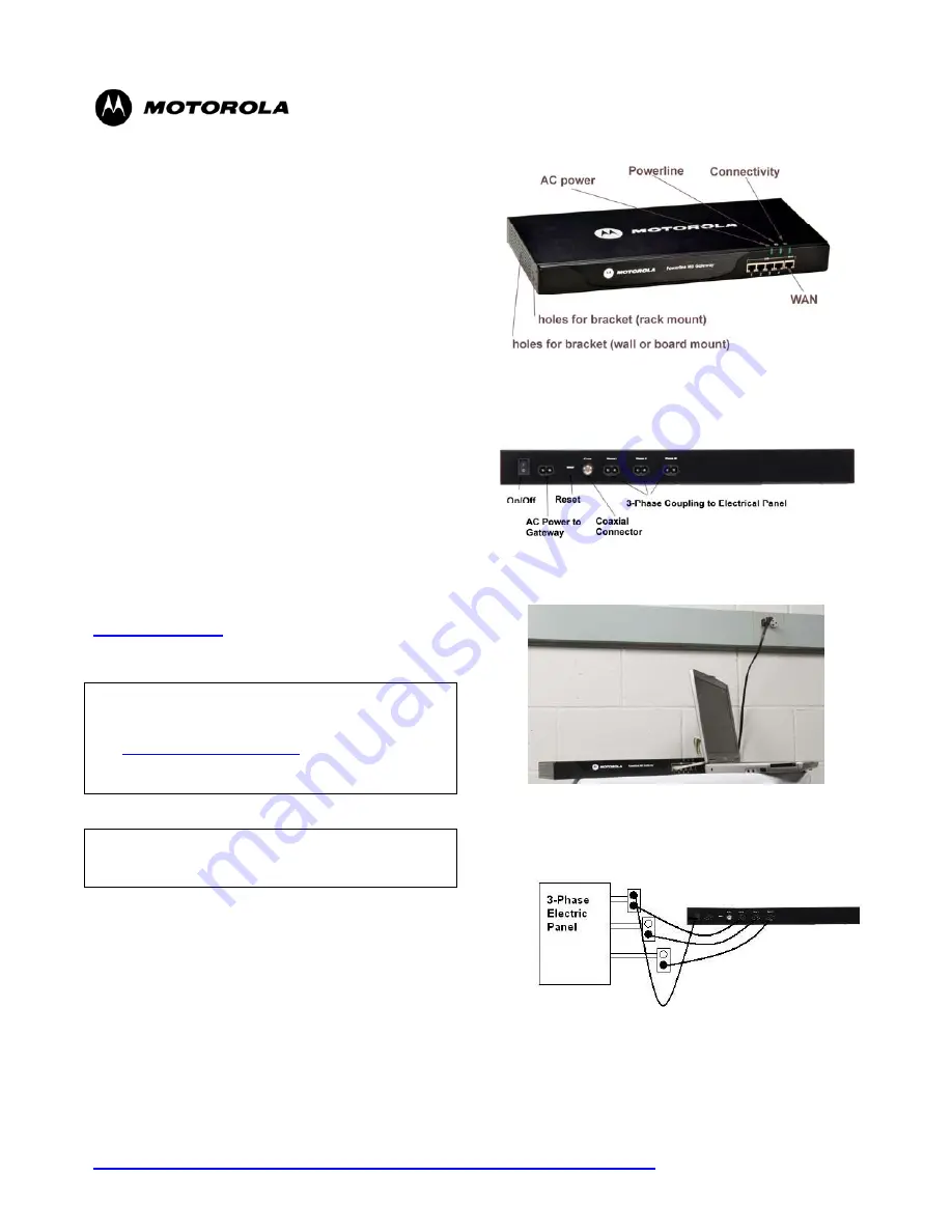
Figure 1 Front of Gateway
Figure 2 Back of Gateway
Figure 3 Test the Gateway
Figure 4 Install the Gateway


