OPTIONAL
PA
R
T
S
E-129
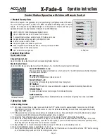
Enables the use of wireless remote controller for ceiling
suspended models.
Photo
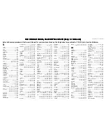
6SHFL¿FDWLRQV
PCA-RP KA
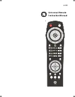
Wireless Remote Controller Kit
PAR-SL94B-E
Unit : mm
Descriptions
Applicable Models
Dimensions
57
40
182
99
31
Cooler/heater button (start/stop) is
provided.
Emergency operation
During operation: LED (green) is lit,
$ODUP/('JUHHQÀDVKHV
Operation indication
Max. 16 refrigerant systems per group
(One or more wireless light receivers
must be installed for each refrigerant
system.)
Number of units controlled
Adapter wiring
9-wire cord (standard accessory) with
connector is connected to the connector
(CN90) on the indoor unit control board.
Light receiver range
7m or less, at within 45 degrees to the front of
receiver (the range varies with conditions)
Operating conditions
Temperature: 0 to 40
͠
, Humidity: 30 to 90%
(no condensation)
Exterior
White gray (Munsell 4.48Y 7.92/0.66), ABS
resin
Installation method
Attached to the brand label case of indoor unit.
for Ceiling Suspended models