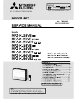
SERVICE MANUAL
<indoor unit>
Models
PEAD-RP35JA(L)Q
PEAD-RP50JA(L)Q
PEAD-RP60JA(L)Q
PEAD-RP71JA(L)Q
PEAD-RP100JA(L)Q
PEAD-RP125JA(L)Q
PEAD-RP140JA(L)Q
TM
1. SAFETY PRECAUTION ····························· 2
2. PART NAMES AND FUNCTIONS ·············· 3
3. SPECIFICATION ········································ 5
4. FAN PERFORMANCE AND
CORRECTED AIR FLOW ·························· 8
5. SOUND PRESSURE LEVELS ···················15
6. OUTLINES & DIMENSIONS ······················22
7. WIRING DIAGRAM ····································24
8. REFRIGERANT SYSTEM DIAGRAM ········25
9. TROUBLESHOOTING ·······························26
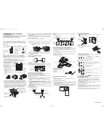
10. DISASSEMBLY PROCEDURE ··················40
CONTENTS
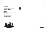
INDOOR UNIT
REMOTE CONTROLLER (option)
ON/OFF
TEMP.
Series PEAD
R410A
2010
SPLIT-TYPE, HEAT PUMP
AIR CONDITIONERS
NOTE:
• This manual describes only
service data of the indoor
units.