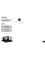
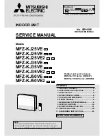
background image

INDOOR UNIT

Models

MFZ-KJ25VE


-


E1

MFZ-KJ25VE


-


E2

 ,


ER2

MFZ-KJ25VE2


-


E1

 ,


ER1

MFZ-KJ35VE


-


E1

MFZ-KJ35VE


-


E2

 ,


ER2

MFZ-KJ35VE2


-


E1

 ,


ER1

MFZ-KJ50VE


-


E1

 ,


ER1

MFZ-KJ50VE2


-


E1

 ,


ER1

SERVICE MANUAL

PARTS CATALOG (OBB666)

CONTENTS

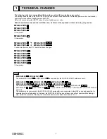
1. TECHNICAL CHANGES ···································

3

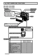
2. PART NAMES AND FUNCTIONS ·····················

4

3. SPECIFICATION ················································

5

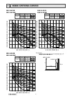
4. NOISE CRITERIA CURVES ······························

6

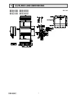
5. OUTLINES AND DIMENSIONS ························

7

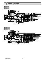
6. WIRING DIAGRAM ············································

8

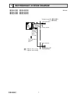
7. REFRIGERANT SYSTEM DIAGRAM ···············9
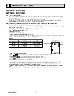
8. SERVICE FUNCTIONS ···································

10

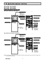
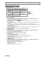
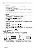
9. MICROPROCESSOR CONTROL ···················

12

10. TROUBLESHOOTING ·····································

20

11. DISASSEMBLY INSTRUCTIONS ····················

35

NOTE: 

• This service manual describes technical data of the indoor units.

• RoHS compliant products have <G> mark on the spec name plate.

  For servicing of RoHS compliant products, refer to the RoHS Parts List.

No. OBH666

REVISED EDITION-C

Outdoor unit service manual

MUFZ-KJ•VE Series (OBH667)

MUFZ-KJ•VEHZ Series (OBH668)

Please void OBH666 REVISED EDITION-B.

Revision C:

 • MFZ-KJ25VE2- 

E1

ER1

, MFZ-KJ35VE2- 

E1

ER1

 and MFZ-KJ50VE2- 

E1

ER1

 have been 

added.

Summary of Contents for MFZ-KJ25VE

Page 1: ...ANT SYSTEM DIAGRAM 9 8 SERVICE FUNCTIONS 10 9 MICROPROCESSOR CONTROL 12 10 TROUBLESHOOTING 20 11 DISASSEMBLY INSTRUCTIONS 35 NOTE This service manual describes technical data of the indoor units RoHS compliant products have G mark on the spec name plate For servicing of RoHS compliant products refer to the RoHS Parts List No OBH666 REVISED EDITION C Outdoor unit service manual MUFZ KJ VE Series OB...

Page 2: ...spection of the circuit needs to be done without turning off the power exercise great caution not to touch the live parts Use the specif ed refrigerant only Never use any refrigerant other than that specified Doing so may cause a burst an explosion or fire when the unit is being used serviced or disposed of Correct refrigerant is specified in the manuals and on the spec labels provided with our pr...

Page 3: ... or MFZ KJ50VE2 E1 ER1 is connectable with the MUFZ KJ VE HZ outdoor unit or the MXZ out door unit This model may be connected to the MUFZ KJ VE HZ series after once connected to the MXZ series and operated for example because of relocation In that case the MUFZ KJ VE HZ series outdoor units will not operate without taking a step Follow the procedure Deleting the memorized abnormal condition descr...

Page 4: ...5 35 50VE2 Air filter Nano platinum filter MFZ KJ25 35 50VE Air purifying filter MFZ KJ25 35 50VE2 Panel Front panel Horizontal vane Vertical vane Multi flow vane ACCESSORIES MFZ KJ25VE MFZ KJ25VE2 MFZ KJ35VE MFZ KJ35VE2 MFZ KJ50VE MFZ KJ50VE2 Remote controller holder 1 Fixing screw for 3 5 x 16 mm Black 2 Pipe cover 1 Band 2 Battery AAA for remote controller 2 Indoor unit mounting bracket 1 Fixing s...

Page 5: ... 35 45 Med 30 40 Low 25 35 Silent 19 29 Fan speed Cooling Super High rpm 790 980 High 700 880 Med 600 770 Low 520 670 Silent 440 580 Heating Super High rpm 910 1 250 High 750 1 060 Med 630 890 Low 540 750 Silent 440 610 Fan speed regulator 5 Remote controller model SG132 MFZ KJ VE SG161 MFZ KJ VE2 NOTE Test conditions are based on ISO 5151 Cooling Indoor Dry bulb temperature 27 C Wet bulb temperat...

Page 6: ...E LEVEL dB re 0 0002 MICRO BAR BAND CENTER FREQUENCIES Hz COOLING FUNCTION 39 41 SPL dB A LINE Super High FAN SPEED HEATING NC 10 MFZ KJ25VE MFZ KJ25VE2 INDOOR UNIT WALL 1m 1m MICROPHONE Test conditions Cooling Dry bulb temperature 27 C Wet bulb temperature 19 C Heating Dry bulb temperature 20 C MFZ KJ35VE MFZ KJ35VE2 MFZ KJ50VE MFZ KJ50VE2 NC 60 NC 50 NC 40 NC 30 NC 20 NC 70 80 70 60 50 40 30 20 ...

Page 7: ...7 OUTLINES AND DIMENSIONS 5 Unit mm MFZ KJ25VE MFZ KJ25VE2 MFZ KJ35VE MFZ KJ35VE2 MFZ KJ50VE MFZ KJ50VE2 OBH666C ...

Page 8: ...8 6 WIRING DIAGRAM MFZ KJ25VE MFZ KJ35VE MFZ KJ50VE MFZ KJ25VE2 MFZ KJ35VE2 MFZ KJ50VE2 OBH666C ...

Page 9: ... RT15 main RT13 sub Flared connection Refrigerant flow in cooling Refrigerant flow in heating Refrigerant pipe 9 52 MFZ KJ25 35 12 7 MFZ KJ50 with heat insulator Refrigerant pipe 6 35 with heat insulator Indoor coil thermistor RT12 main Distributor Unit mm MFZ KJ25VE MFZ KJ25VE2 MFZ KJ35VE MFZ KJ35VE2 MFZ KJ50VE MFZ KJ50VE2 OBH666C ...

Page 10: ...R A PARTICULAR INDOOR UNIT A maximum of 4 indoor units with wireless remote controllers can be used in a room To operate the indoor units individually with each remote controller assign a number to each remote controller according to the number of the indoor unit This setting can be set only when all the following conditions are met The remote controller is powered OFF Weekly timer is not set Week...

Page 11: ...l the compressors may flow simultaneously at restart Therefore the special counter measures are required to prevent the main voltage drop or the rush of the starting cur rent by adding to the system that allows the units to start one by one 8 3 AUTO RESTART FUNCTION When the indoor unit is controlled with the remote controller the operation mode the set temperature and the fan speed are memorized ...

Page 12: ...ontroller Slide it down further to get to the weekly timer buttons WEEKLY TIMER set buttons TIME TIMER set buttons FORWARD button BACKWARD button RESET button i save button VANE CONTROL button AMPM AMPM Signal transmitting section Operation display section TEMPERATURE buttons STOP OPERATE OFF ON button Indication of remote controller model is on back Distance of signal About 6 m Beep s is are hear...

Page 13: ... of shape of the indication Indication Operation state Room temperature The unit is operating to reach the set temperature About 2 C or more away from set tempera ture The room temperature is approaching the set tem perature About 1 to 2 C from set temperature Standby mode only during multi system operation Lighted Blinking Not lighted 9 2 DRY OPERATION 1 Press OPERATE STOP ON OFF MFZ KJ25 35 50VE...

Page 14: ... to detect present room temperature Following the conditions below operation mode is selected If the room temperature thermistor RT11 reads more than set temperature COOL mode is selected If the room temperature thermistor RT11 reads set temperature or less HEAT mode is selected 2 Mode change In case of the following conditions the operation mode is changed COOL mode changes to HEAT mode when 15 m...

Page 15: ...r blows out from the air outlet the multi flow vane may stop moving for up to 10 minutes to make and blow out warm air 2 FLOW 1 FLOW 1 FLOW Vane angle is fixed to position 1 1 FLOW Vane angle is fixed to position 3 3 Positioning The vane presses the vane stopper once to confirm the standard position and then moves to the set angle Confirming of standard position is performed in case of follows a T...

Page 16: ...set time increases by 1 minute and each time BACKWARD button is pressed the set time decreases by 1 minute Pressing those buttons longer the set time increases decreases by 10 minutes c Press the CLOCK set button 2 Press OPERATE STOP ON OFF MFZ KJ25 35 50VE STOP OPERATE OFF ON MFZ KJ25 35 50VE2 button to start the air conditioner 3 Set the time of timer ON timer setting a Press ON TIMER button dur...

Page 17: ...d down the button to change the time quickly The temperature can be set between 16 C and 31 C at weekly timer blinks Pressing selects the day of the week to be set Pressing selects the setting number E g Mon Tue Sun and 1 are selected All days can be selected NOTE The simple ON OFF timer setting is available while the weekly timer is on In this case the ON OFF timer has priority over the weekly ti...

Page 18: ...EAT mode i save operation is 10 C and 16 31 C 2 groups of setting can be saved One for COOL one for HEAT i save operation and the weekly timer operation cannot be used together 2 How to cancel operation Press i save button again i save operation can also be cancelled by pressing OPERATION SELECT button to change the operation mode The same setting is selected from the next time by simply pressing ...

Page 19: ...C The fan speed shifts to Medium The coil frost prevention works even in the test run or the emergency operation In the test run or emergency operation the horizontal vane operates in VANE AUTO mode Emergency operation continues until EMERGENCY OPERATION switch is pressed once or twice or the unit receives any signal from the remote controller In the latter case normal operation will start NOTE Do...

Page 20: ...When troubleshooting Refer to 10 2 10 3 and 10 4 4 How to replace batteries Weak batteries may cause the remote controller malfunction In this case replace the batteries to operate the remote controller normally Lead wiring Connector housing Incorrect Correct Press RESET button with a thin instrument and then use the remote controller Remove the front lid and insert batteries Then reattach the fro...

Page 21: ...t is abnormal The indoor unit is abnormal Check the blinking pattern and identify the abnormal point by referring to the indoor unit failure mode table Refer to indoor unit service manual Make sure to check at least 2 consecutive blinking cycles 2 Releasing the failure mode recall function Release the failure mode recall function by the following procedures Turn OFF the power supply and turn it ON...

Page 22: ...al signal error The serial signal from the outdoor unit is not received for a maximum of 6 minutes 1 time flash every 0 5 second Refer to the characteristics of the room temperature thermistor 10 7 Room temperature thermistor The room temperature thermistor short or open circuit is detected every 8 seconds during operation Not lighted Normal Left lamp of OPERATION INDICATOR lamp 13 time flash 2 5 ...

Page 23: ... lamp 3 time flash Cause Indoor unit Trouble of indoor fan motor Left lamp 5 time flash Cause Outdoor unit Outdoor power system abnormality Left lamp 6 time flash Cause Outdoor unit Trouble of thermistor in outdoor unit Left lamp 7 time flash Cause Outdoor unit Trouble of outdoor control system Check room temperature thermistor and indoor coil thermis tor Refer to 10 7 Test point diagram and volta...

Page 24: ...utdoor thermistor Refer to the outdoor unit service manual Refer to Check of inverter compressor Refer to the outdoor unit service manual Check the stop valve Replace the inverter P C board or the outdoor electronic control P C board Refer to the outdoor unit service manual 3 Indoor fan motor 7 Abnormal point Room tempera ture thermistor Left lamp flashes 2 time flash 2 5 second OFF The indoor coi...

Page 25: ...f the lead wire BRN other one 350 Ω Horizontal vane motor MV2 BACK Measure the resistance between the terminals with a tester Part temperature 10 C 30 C Check 10 6 Check of indoor fan motor and Check of indoor electronic control P C board and indoor fan motor Normal 219 Ω 273 Ω BRN other one 250 Ω Color of the lead wire Normal 219 Ω 273 Ω BRN other one 250 Ω Color of the lead wire OPERATION INDICA...

Page 26: ...ait 5 seconds or more and then press EMERGENCY OPERATION switch Measure the supply voltage as follows within 12 seconds after EMER GENCY OPERATION switch is pressed If more than 12 seconds passes turn OFF the power supply and turn it ON again then measure the voltage Indoor electronic control P C board 1 Measure the voltage between CN211 and 2 Measure the voltage between CN211 and If more than 12 ...

Page 27: ...er P C board Assign a number of remote controller Refer to 8 2 Check if the unit operates with the remote controller Does the unit operate with the remote controller Yes No OK Measure the voltage between display receiver P C board connector CN301 and when the remote controller button is pressed Is the voltage approximately 4 VDC 5 VDC No Yes Replace the indoor electronic control P C board 1 Look a...

Page 28: ... sure to check both the fuse and the varistor in any case Is the fuse F11 blown only Measure the resistance between CN211 and of indoor fan motor connector 1 2 Yes Is the resistance 1MΩ or more Replace the fuse F11 and the indoor fan motor 3 No Replace the fuse F11 3 Measure the resistance of resis tor R111 on the indoor electronic control P C board Is the resistance of resistor R111 approxi matel...

Page 29: ...utes after the power supply is turned on Touch S2 and S3 with tester probes and start the emergency operation No Turn the power supply ON When the emergency operation starts does the rated voltage occur for 2 seconds between indoor terminal block S2 and S3 Yes Replace the indoor electronic control P C board Does the left lamp of the OPERA TION INDICATOR lamp on the indoor unit blink continuously 6...

Page 30: ... No Does DC 10 V or more occur between L68A and L68B on the outdoor relay P C board Yes Does the outdoor LED blink 6 times Yes Replace the outdoor relay P C board 1 No Does DC more than 0 V occur between indoor terminal block S2 and S3 Yes Replace the outdoor inverter P C board 1 No Turn the power supply OFF Start the emergency operation No Repair has been completed Replace the outdoor inverter P ...

Page 31: ...ess EMERGENCY OPERATION switch once Does the left lamp of the OPERATION INDICATOR lamp light up Conf rmation of the power to the indoor unit Yes No Is serial signal error indicated 6 minutes later Yes No Is there any miswiring poor contact or wire disconnection of the indoor outdoor connect ing wire Yes Correct them No A Turn OFF the power supply Check once more if the indoor outdoor connecting wi...

Page 32: ...r display P C board or the outdoor control P C board repeat quick BLINKING and OFF 2 If the trouble sometimes occurs possible causes are as follows Poor connection of the indoor outdoor connecting wire Check for intermediate connection of the indoor outdoor connecting wire loose connection to the terminal block and cut wire inside the cable If any of them is found correct the problem s Effects of ...

Page 33: ...ions such as antennas or wiring Check the following before asking for service 1 Devices affected by the electromagnetic noise TV sets radios FM AM broadcast shortwave 2 Channel frequency broadcast station affected by the electromagnetic noise 3 Channel frequency broadcast station unaffected by the electromagnetic noise 4 Layout of indoor outdoor unit of the air conditioner indoor outdoor wiring ea...

Page 34: ...istor NR11 Indoor coil thermistor CN112 Indoor coil thermistor RT15 MAIN 3 Indoor coil thermistor RT14 MAIN 2 Indoor coil thermistor RT12 MAIN 1 Indoor coil thermistor RT13 SUB Serial signal input CN202 Connect to display receiver P C board CN1J1 Interface CN105 Indoor fan motor CN211 0 or 15 VDC 3 6 VDC 15 VDC GND high voltage DC 325 VDC Connector cable CN104 Timer short mode point 2 points Refer...

Page 35: ...control P C board Fan motor connector CN211 Photo 5 Indoor coil thermistor connector CN112 Photo 5 7 Rotate the display receiver P C board holder to the right side and disconnect the vane motor relay con nector Photo 6 8 Disengage the electrical box from the upper catch and pull out the electrical box from the box 35 DISASSEMBLY INSTRUCTIONS 11 1 Slide the sleeve and check if there is a locking le...

Page 36: ...6 4 Removing the nozzle assembly 1 Remove the panel Refer to 1 2 Rotate the display receiver P C board holder to the right side and disconnect the vane motor relay con nector 3 Remove the fixed screws on the both sides of the nozzle 4 Disengage the catches on the nozzle from the box 5 Hold the both sides of the nozzle Rotate the nozzle toward you around the right and left ribs to remove it Photo 7...

Page 37: ... it from the rib on the multi flow vane Slide the vane shaft in arrow 2 direction and separate it from the unit body Multi flow vane 1 1 See the figure below and push to open the indicated places on the horizontal vanes between front and back with your fingers so that you can access 4 vane shafts positioned on the back of the horizontal vanes vane shafts on each horizontal vane 2 1 Open the horizo...

Page 38: ...zontal vane motor Connect the connectors to the horizontal vane motors by referring to the colors red and white noted on the vane motor support Photo 9 Photo 10 Photo 11 Photo 12 6 Removing the multi flow vane motor unit 1 Remove the panel Refer to 1 2 Disconnect the connector from the multi flow vane motor unit 3 Remove the screws of the multi flow vane motor unit and pull out the multi flow vane...

Page 39: ... together with the indoor fan motor and the motor band 8 Disengage the catches on the motor band and remove the motor band and pull out the indoor fan motor 9 Remove the screws fixing the both sides of the heat exchanger 10 Disengage the catch on the right side on the heat exchanger 11 Lift the heat exchanger and pull out the line flow fan upward Photo 16 Photo 13 Photo 14 Photo 15 Photo 17 39 Scr...

Page 40: ...ed in Jan 2014 No OBH666 REVISED EDITION B Distributed in Oct 2013 No OBH666 REVISED EDITION A Distributed in Jun 2013 No OBH666 Made in Japan HEAD OFFICE TOKYO BLDG 2 7 3 MARUNOUCHI CHIYODA KU TOKYO 100 8310 JAPAN New publication effective Jan 2016 Specifications are subject to change without notice OBH666C ...

Reviews: