background image


1 / 47 

JEP0-IL9537 


Numerical Relay   
MELPRO

TM

-S 

Series


MODEL 

CBV2 - A02S1 
COC4 - A02S1 


OPERATION MANUAL 


Summary of Contents for MELPRO CBV2 -A02S1

Page 1: ...1 47 JEP0 IL9537 Numerical Relay MELPROTM S Series MODEL CBV2 A02S1 COC4 A02S1 OPERATION MANUAL ...

Page 2: ...nger Caution Furthermore even with items described as Caution there is the possibility of serious consequences depending on the situation All of the described contents are important Therefore be sure to comply with them Transportation Caution Transport the equipment in the correct orientation Do not apply excessive shock and or vibration as this could affect the performance and life of the product...

Page 3: ... of failure or fire Operating and Setting the equipment Danger The equipment must only be operated and handled by qualified personnel Otherwise there are risks of electric shock injury failure malfunction and maloperation Handling and maintenance of the equipment must only be carried out after gaining a thorough understanding of the instruction manual Otherwise there is the risk of electric shock ...

Page 4: ... Ambient temperature 20 10 C Relative humidity 90 or less External magnetic field 80 A m or less Atmospheric pressure 86 to 106 103 Pa Mounting angle Regular direction 2 Frequency Rated frequency 1 Waveform in the case of AC Distortion factor 2 or less Distortion factor Effective value of higher harmonics only 100 Effective value of fundamental wave AC component in the case of DC Ripple factor 3 o...

Page 5: ...ble or not compensation for accidents and compensation for damages to products other than MITSUBISHI ELECTRIC CORPORATION products and other tasks 4 Applications of products 1 The user is requested to confirm the standards the regulations and the restrictions which should be applied in case of utilizing products described in this catalogue and another one in combination Also the user is requested ...

Page 6: ...after 15 years have been passed from ex work of products 2 Product supply including repair parts is not available after production is discontinued 6 Changes in product specification The specification given in the catalogue manuals or technical documents are subject to change without prior to notice 7 Scope of service The technical service fee such as engineer dispatching fee is excluded in the pri...

Page 7: ...ons and performances enough to use the product properly It is necessary to forward this instruction manual to end users and a person in charge of maintenance This OPERATION MANUAL explains front panel operation human machine interface HMI and how to use it The MELPRO S series main function such as protection function overview operation method should be read each relay device instruction manual ...

Page 8: ...ent RECORD ELE 21 4 4 Relay Element Detection before Trip PICK UP 24 4 5 Display Relay Element Setting DISP SET 26 4 6 Change Relay Element Setting SETTING 27 4 6 1 Under Protection by Password 27 4 6 2 Set Numerical Values 30 4 6 3 Set UV TEST Mode for CBV2 31 4 6 4 Set IDMT Characteristic Curve for COC4 32 4 6 5 Set FREQ 33 4 6 6 Set ALARM HOLD 34 4 6 7 Set COMM ST No 35 4 6 8 Set PASSWORD 36 4 ...

Page 9: ...otected human machine interface enables secured operation Highly Accurate Digital Computation The digital computation using high speed sampling minimizes the effect of harmonics etc and provides highly accurate protection Self diagnosis The continuously monitoring of electronic circuits from input to output can detect internal failure before the failure causes damage on the power system Compact si...

Page 10: ...AB Phase BC Phase CA Phase Display RUN LED green Indicate the result of automatic self diagnosis This LED is turned on for normal and turned off for abnormal ALARM LED red Indicate the result of automatic self diagnosis This LED is turned off for normal and turned on for abnormal Self diagnosis ALARM An electronic circuit and a built in power supply are always supervised and it outputs to the RUN ...

Page 11: ...or equal to 50 ms Ground inst OC 50N Operation value LOCK 2 0 20 0 A 0 5 A step 2 Operation time INST less than or equal to 40 ms Forced operation Trip and control annunciator contacts can be forced to operate Operation indication Operation indicator LED comes on when the relay element operates LED indication A Phase B Phase C Phase Zero sequence Instantaneous overcurrent element Display RUN LED g...

Page 12: ...ol and alarm Make 10 VA cos 0 4 10 W L R 0 007 s Case Cover Color N1 5 Mass approx 1 2kg 1 When DC125V is used please note that the maximum voltage of operation range is still 143V A maximum is not 125V x 30 2 If it sets to LOCK the protection element will be in a lock state of operation ...

Page 13: ...mounted The switch name and position is shown in Fig 3 1 and Fig 3 2 When each rotary switch set no assigned position the 7 seg LED is turned off Switch 1 SW1 Switch 2 SW2 Switch 3 SW3 Switch 4 SW4 Fig 3 1 Rotary switch assign switch 1 4 1 2 3 5 4 9 13 16 Fig 3 2 Rotary switch position number 1 16 are clockwise ...

Page 14: ... RECORD RESET Clear Fault Record Data Clause 4 9 14 DISP ERR CODE Display Error Code by Self Diagnosis Clause 4 10 15 ERR CODE RESET Clear Error Code Clause 4 11 16 No assigned Table 3 2 Select items of Switch 1 COC4 Rotary position of Switch 1 COC4 A02S1 Description Related chapters Protectable items by password 1 MEASURE Real Time Measurement Clause 4 1 2 RECORD RMS Fault Record Measurement Valu...

Page 15: ...ed Table 3 3 Measurement items of Switch 2 CBV2 Rotary position of Switch 2 CBV2 A02S1 Description Related chapters 1 VAB RMS value of phase to phase voltage Clause 4 1 4 2 4 3 2 VBC 3 VCA Table 3 4 Measurement items of Switch 2 COC4 Rotary position of Switch 2 COC4 A02S1 Description Related chapters 1 IA RMS value of phase current Clause 4 1 4 2 4 3 2 IB 3 IC 4 I0 RMS value of zero sequence curre...

Page 16: ...s 14 15 PASSWORD Set password Even though Switch 1 set DISP SET current password doesn t displayed 16 Table 3 6 Setting Item of Switch 3 COC4 Rotary position of Switch 3 COC4 A02S1 Description Related chapters 1 I A IDMT overcurrent operating value 51 Clause 4 5 4 6 2 I TM IDMT overcurrent time multiplier 51 3 I CURVE IDMT characteristic curve 51 4 I A Instantaneous overcurrent operating value 50 ...

Page 17: ... harmonic elements are eliminated by the protection relay s filters The different value would be appeared between this measured value from protection relay and an electrical indicators e g voltage meter or current meter Turn Switch 1 to MEASURE position 1 Turn Switch 2 Indicate measured value on 7 seg LED Indicate value according to position of Switch 2 Indicate value according to position of Swit...

Page 18: ...ng period of one phenomenon is 1 second The measured value which the phase is selected by Switch 2 is displayed In this measured value the harmonic elements are eliminated by the protection relay s filters The different value would be appeared between this measured value from protection relay and an electrical indicators e g voltage meter or current meter Turn Switch 1 to RECORD RMS position 2 Tur...

Page 19: ...d latest phenomenon is indicated Measured value when the relay element was operation is indicated on 7 seg LED The indicating period of one phenomenon is 1 second The corresponding value of the selected phase with Switch 2 is indicated If you turn Switch 2 until going to next phenomenon measured value of this phenomenon is indicated In this case VBC of 2nd phenomenon is indicated ...

Page 20: ...phenomenon goes to next order In this case VBC of 3rd new phenomenon is indicated After the indicating the oldest phenomenon in the save data it goes back to latest 1st phenomenon Above sequence is repeated When you would like to check again or read out other phase value Switch 2 is turned In this case VAB of 1st phenomenon is indicated ...

Page 21: ... protection relay can store ten 10 fault phenomenon The saved fault phenomenon are displayed with rotating in order The indicating period of one phenomenon is 1 second Turn Switch 1 to RECORD ELE position 3 At the beginning the figure one 1 which means latest phenomenon is indicated The condition when relay elements were operated tripped is displayed on the operation indicator ...

Page 22: ...is indicated The condition when relay elements were operated tripped is displayed on the operation indicator Next the figure three 3 which means 3rd latest phenomenon is indicated The condition when relay elements were operated tripped is displayed on the operation indicator ...

Page 23: ...avoid this situation please push INDICATOR RESET button and turn off current LED glowing In case of occurring fault evolution the first tripped condition is saved as latest fault record For example it is considered that a fault evolution from VAB to VBC It is assumed that the VBC fault occurs after few seconds from VAB fault In the beginning the OPERATION INDICATOR of VAB is glowed and this condit...

Page 24: ...s count up reaches to 10 the protection relay trips and digital output DO is closed After relay tripping 7 seg LED indicates U in this PICK UP function If instantaneous operation element you would be difficult to read out the count up figures because count up condition is completed immediately Turn Switch 1 to PICK UP position 4 In the condition before relay trip besides after fault detection 7 se...

Page 25: ...P0 IL9537 The count up condition is continued until reaching 10 When this count up reaches to 10 the protection relay trips and digital output DO is closed and 7 seg LED indicates U The blink of LED is stopped ...

Page 26: ...ning Switch 3 each setting value can be read out Even though the Switch 3 set to PASSWORD position 15 the current password does not be indicated Turn Switch 1 to DISP SET position 5 The setting value linked in Switch 3 position is indicated The indicated data is current setting value By turning Switch 3 each setting value can be checked ...

Page 27: ...Go to clause 4 6 1 When the password isn t set go to clause 4 6 2 4 6 8 4 6 1 Under Protection by Password When the password is set input the password to enter the setting mode If using no password following operation can be passed How to set password shows sub clause 4 6 8 1 Input Password When the password lock is enabled 000 is indicated The blinking LED shows the operated digit You can change ...

Page 28: ...ted digit You can change the figure using Switch 4 After no operation for 2 seconds blinking digit is moved to right No operation for 2 seconds blinking digit is moved to right D E Turn Switch 4 to input the password Go to sub clause 4 6 1 2 or 4 6 1 3 ...

Page 29: ...d is correct the setting value linked in Switch 3 position is indicated Go to sub clause 4 6 2 4 6 8 3 If Wrong Password Inputted password is indicated As an example it is show that correct password is 205 but 201 is inputted Blinking LED moves to left And indicated values on 7 seg LED goes back to zero 000 Please try again inputting password D E ...

Page 30: ... current setting value all LEDs are blinking You can select new value using Switch 4 Under blinking condition you can select a setting value After no operation for 2 seconds blinking is stopped The indicated value is saved as a new setting value This new value is enabled for relay element immediately Therefore in service condition DON T change the relay setting ...

Page 31: ...tems of the UV TEST Table 4 1 LED indication for test mode CBV2 LED Indication Detail This value means OFF setting of the Test Mode in the over under voltage element This value means AB phase setting of the Test Mode in the over under voltage element This value means BC phase setting of the Test Mode in the over under voltage element This value means CA phase setting of the Test Mode in the over u...

Page 32: ...54 1 c 0 4 DT01 Definite Time Refer to equation 4 2 5 DT INST Instantaneous operation 6 NI11 Normal Inverse IEEE Moderately Inverse In equation 4 1 k 0 0515 0 02 c 0 114 7 EI11 Extremely Inverse IEEE Very Inverse In equation 4 1 k 19 61 2 c 0 491 8 EI12 Extremely Inverse IEEE Extremely Inverse In equation 4 1 k 28 2 2 c 0 1217 9 NI21 Normal Inverse In equation 4 1 k 2 4 0 4 c 1 2 10 VI21 Very Inve...

Page 33: ...re in service condition Turn Switch 3 to FREQ position 10 The current setting value is indicated This example shows 50Hz as a setting value After showing current setting value all LEDs are blinking You can select new value using Switch 4 After No operation for few seconds blinking is stopped The indicated value is saved as a new value ...

Page 34: ...rror code Refer to clause 4 10 After recovering from error with ALARM HOLD OFF ON OFF OFF Enable If the intermittently or temporarily fault conditions is occurred the protection relay could recover after the error cleared If the error cannot cleared the behavior of the Error condition is continued After recovering from error with ALARM HOLD ON OFF ON ON Lock disable Regardless of the cause of erro...

Page 35: ...e slave address in MODBUS More details please refer to MELPRO S series MODBUS Communication Instruction Manual Turn Switch 3 to COM ST No position 13 The current setting value is indicated After showing current setting value all LEDs are blinking You can select new value using Switch 4 ...

Page 36: ...After setting password the entering password is needed for some items More details please refer to section 3 2 By this password some operation items of Switch 1 are protected The protected items are shown in Table 3 1 and Table 3 2 How to input the password refer to clause 4 6 1 Turn Switch 1 to SETTING position 7 Turn Switch 3 to PASSWORD position 15 Setting digit is blinking ...

Page 37: ...9537 Turn Switch 4 to change the password After no operation for 2 seconds blinking digit is moved to right After no operation for 5 seconds blinking digit is moved to right D E Turn Switch 4 to change the password ...

Page 38: ...38 47 JEP0 IL9537 After no operation for 2 seconds blinking is stopped These indicated values are saved as new password ...

Page 39: ... function is enabled please refer to clause 4 6 1 Following operation steps shows the condition after inputting correct password If password function is not used the condition directly goes to following steps Turn Switch 1 to FORCED OP TRIP position 8 The EL1 is indicated This means that the digital output for the trip contact can be operated Push PORCED OPERATION button ...

Page 40: ...er supply ALARM contact Trip contact 14 Trip contact ALARM contact Earth circuit RS485 NETP RS485 NETSG RS485 NXTN The functions of these terminals are dependent on each protection device The functions of these terminals are dependent on each protection device Trip contact closes Terminal no 13 14 ...

Page 41: ...nputting correct password If password function is not used the condition directly goes to following steps The relationship between the rotary position of Switch 1 and the displayed value in 7 seg LED are shown in Table 4 4 Table 4 4 Relationship between Switch 1 position and the 7 seg LED Rotary position of Switch 1 Displayed value in 7 seg LED COC4 CBV2 9 EL2 10 EL3 11 EL4 Turn Switch 1 to FORCED...

Page 42: ...upply ALARM contact Trip contact 14 Trip contact ALARM contact Earth circuit RS485 NETP RS485 NETSG RS485 NXTN The functions of these terminals are dependent on each protection device The functions of these terminals are dependent on each protection device The contact close the operated terminal number depends on the relay model ...

Page 43: ...ondition after inputting correct password If password function is not used the condition directly goes to following steps Turn Switch 1 to RECORD RESET position 13 After the Switch 1 setting this position the remaining time until the deletion is shown in the progress bar on 7 seg LED The time until deletion start is about 3 seconds When you would like to CANCEL the deletion please change Switch 1 ...

Page 44: ...tion relay has no error nothing is displayed Table 4 5 Description of error code Error code Details 01 ROM check 02 RAM check 03 Analog input A I check 04 A D operating check 05 Digital output D O condition check 06 Digital output D O operation check 07 Analogue filter check 10 Watch dog timer WDT check 12 A D accuracy check Turn Switch 1 to DISP ERR CODE position 14 The error code is appeared Thi...

Page 45: ...r inputting correct password If password function is not used the condition directly goes to following steps Turn Switch 1 to ERR CODE RESET position 15 After the Switch 1 setting this position the remaining time until the deletion is shown in the progress bar on 7 seg LED The time until deletion start is about 3 seconds When you would like to CANCEL the deletion please change Switch 1 to other po...

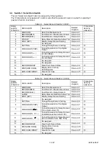
Page 46: ...46 47 JEP0 IL9537 ...

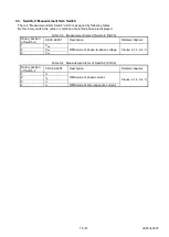
Page 47: ...47 47 JEP0 IL9537 ...

Page 48: ...48 48 JEP0 IL9536 HEAD OFFICE 7 3 MARUNOUCHI 2 CHOME CHIYODA KU TOKYO 100 8310 JAPAN Revised in Jan 2019 ...

Reviews: